Flavel Caress Installation And Maintenance Instructions Manual
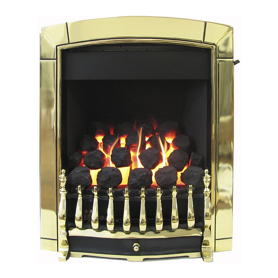
Coal effect gas fire
Hide thumbs
Also See for Caress:
- Installation, maintenance & user instructions (64 pages) ,
- Installation, maintenance & user instructions (67 pages)
Table of Contents

Related Manuals for Flavel Caress


Summary of Contents for Flavel Caress
- Page 1 Caress Slimline SC COAL EFFECT GAS FIRE Installation and Maintenance Instructions Hand these instructions to the user Model No’s FNVC**SN is for use on Natural Gas (G20) at a supply pressure of 20 mbar in G.B. / I.E. ** denotes trim & fret variant...
-
Page 2: Table Of Contents
Installing the fire box 10-16 Gas tightness and burner pressure Section 3 Assembling Fuel Bed and Commissioning Assembling the ceramics and fuel bed 18-21 Fitting the Caress trim Fitting the fret Lighting the appliance Checking for clearance of combustion products 25-26 Section 4... -
Page 3: Information And Requirements
SECTION 1 INFORMATION AND REQUIREMENTS APPLIANCE INFORMATION Model FNVC**SN ** denotes trim & fret variant Gas Type Main injectors (2 off) Size 235 Pilot Type S.I.T. Oxystop YA OP 9055 Max. Gross Heat Input : 6.5 kW Min. Gross Heat Input : 4.2 kW Cold Pressure : 20.0 +/-1.0 mbar (G20) -
Page 4: Conditions Of Installation
INSTALLATION REQUIREMENTS CONDITIONS OF INSTALLATION In Great Britain :- It is the law that all gas appliances are installed only by a CORGI Registered Installer, in accordance with these installation instructions and the Gas Safety (Installation and Use) Regulations 1998 as amended. Failure to install appliances correctly could lead to prosecution. -
Page 5: Fireplace / Surround Suitability
FIREPLACE / SURROUND SUITABILITY The fire must only be installed on a hearth it must not be installed directly onto carpet or other combustible floor materials. The fire is suitable for fitting to non-combustible fire place surrounds and propri- etary fire place surrounds with a temperature rating of at least 150 o c. If a heating appliance is fitted directly against a wall without the use of a fire surround or fire place all combustible material must be removed from behind the trim. -
Page 6: Fire Place Opening / Catchment Space
There must be no leakage of smoke through the structure of the chimney during or after the smoke pellet test and it is important to check inside upstairs rooms adjacent to the chimney / flue. Check the chimney pot / terminal and general condition of the brickwork or masonry. - Page 7 Table A - Installation Depth Requirements for a Flavel Caress Slimline SC being installed into a brick built chimney, requiring 12.0 litres of debris collection volume (fig. 2) 330 (minimum opening width) 430 (maximum opening width) For example, if the appliance was to be fitted into a 400mm wide opening, the depth required would be 189mm.
-
Page 8: Fitting To Chair Bricks
1.7 FITTING TO FIREPLACES WITH EXISTING CHAIRBRICKS AND CONVENTIONAL BRICKBUILT CHIMNEYS This appliance is suitable for use in fireplaces fitted with an existing chairbrick without the need for removal of the chairbrick, providing the minimum depth of the fireplace exceeds 190mm. If the depth is less than 190mm then the spacer (optional) must be used to give a minimum clearance from the rear of the fire to the rear of the chairbrick of at least 90mm to allow sufficient space for the collec- tion of debris which may fall down the chimney. -
Page 9: Hearths
1.10 HEARTHS This appliance must only be installed on to a concrete or non-combustible hearth. The hearth material must be a minimum thickness of 13mm with the top surface at least 50mm above the floor. The hearth must be fitted symmetrically about the fire opening and have a minimum width of 760mm and a minimum projection of 300mm forwards from the fire opening. -
Page 10: Installation Of Fire
SECTION 2 INSTALLATION OF FIRE UNPACKING THE FIRE Carefully lift the fire out of the carton. Remove the loose item packaging carefully from the front of the appliance. Check the contents as listed :- Packing Check List 1 off Fire box / burner assembly 1 off Cast trim 1off... - Page 11 To remove the burner, proceed as follows: Remove the trim, which is secured by two screws at the bottom L/H & R/H sides of the trim. Remove the burner heat shield from the front of the fire box to allow access to the burner. See fig. 3 below. Fig.
- Page 12 Fig. 4 Unscrew the burner assembly fixing screws at either side of the firebox, and the two fixing screws at the base of the fire (See fig. 5 below). Carefully pull the base of the burner forwards from the fuel-bed support panel.
- Page 13 Continue for all models Whilst the fire box is still in position, decide which side the gas supply is to enter the fire from. If concealed pipe work is required plan the pipe run to enter the fire box through one of the openings in the sides of the fire box below the fuelbed sup- port panel and connect to the isolating / inlet elbow.
- Page 14 IMPORTANT : Sealing of the Gas Unused Gas Pipe Inlet Apertures In line with current CORGI regulations, it is imperative that the gas supply inlet apertures that are not utilised during the installation are sealed with the foil tape as supplied. Failure to seal these inlet apertures could lead to flame reversal, which in turn will damage the burner and control systems of the product.
- Page 15 The preferred method of fixing which is suitable for almost all situations is the cable fixing method which is described in the following section in detail. To fit using the preferred cable method proceed as follows- Mark out and drill 4 off No 14 (6mm) holes in the back face of the fire opening in the positions shown below in fig.
- Page 16 Fig. 9 Evenly tighten the tensioning nuts to tension both cables and pull the fire snugly against the wall. Do not overtighten, it is only necessary to pull the seal up against the sealing face of the wall, it does not need to be compressed.
-
Page 17: Gas Tightness And Burner Pressure
NOTE : The cable is factory set, and therefore should need no adjustment Refit the front burner heat shield to the sides of the fire box (2 Screws) Before making the final gas connection, thoroughly purge the gas supply pipework to remove all foreign matter, otherwise serious damage may be caused to the gas control valve on the fire. - Page 18 GAS TIGHTNESS AND INLET PRESSURE Remove the pressure test point screw from the inlet elbow pressure test point and fit a manometer. Turn on the main gas supply and carry out a gas tightness test. Depress the control lever to the position marked pilot. Hold down the control lever for a few seconds to purge the pipe work.
-
Page 19: Assembling The Ceramics And Fuel Bed
ASSEMBLING THE CERAMICS AND FUEL BED NOTE : The position of the fuel-bed components are critical to the performance of the product. Therefore please ensure that the fuel-bed components are positioned as described in the following section prior to requesting a service call due to soot build up, poor flame pattern etc. Place the fuel-bed base centrally on to the fuelbed support and pull fully forwards to the burner. - Page 20 Place the right hand front coal rail moulding onto the front ceramic rail support as shown below in Fig. 13 Fig. 13 Fit four large coals behind the ceramic front rails as shown below in Fig. 14 Fig. 14...
- Page 21 Select three of the small coals and fit onto the ribs of the fuel-bed base. See fig. 15 below Fig. 15 Select the remaining four small coals and arrange along the rear of the fuelbed, directly behind the third row of coals. See fig. 16 below. Fig.
-
Page 22: Fitting The Caress Trim
Ensure the coals sizes are correctly positioned as shown in Fig 17 below. “L” denotes “large” coals and “S” denotes small coals. If any coals are missing, please contact your retailer. Do not proceed with the installation. Fig. 17 Ensure the flame paths are un-interrupted as shown below in Fig. 18. If necessary, make minor adjustments to the coal positions to ensure the flame paths indicated by the arrows are available. - Page 23 FITTING THE TRIM - CARESS MODELS ONLY Fit the 4 off mounting brackets supplied with the fire in the loose items pack to the rear face of the Cast-Iron Trim as shown below in Fig. 19 Fig.
-
Page 24: Fitting The Fret
Fit the fascia to the firebox by hooking the mounting brackets into the slots on the firebox as indicated in Fig. 20 Fig. 20 Image shows bottom right hand slot, further slots are position on mounting flange at opposite side and top L/H / R/H mounting flanges FITTING THE FRET... -
Page 25: Lighting The Appliance
LIGHTING THE APPLIANCE Turn on the isolation valve. Depress the control lever fully downwards to the position marked. Hold down the control lever for a few seconds to allow the gas to reach the pilot. The fire will then begin its ignition sequence. If the pilot does not light, continue to press the control lever until ignition occurs. - Page 26 If spillage persists, the flue is not functioning correctly and a fault exists. If, after investigation the fault cannot be traced and rectified, the fire must be disconnected from the gas supply and expert advice obtained. If there is an extractor fan fitted any where in the vicinity of the appliance, or in adjacent rooms the spillage test should be repeated with the fan running on maximum and all interconnecting doors open.
-
Page 27: Maintenance
Servicing Notes Servicing should be carried out annually by a competent person such as a CORGI registered engineer. This is a condition of the Flavel guarantee schemes. The service should include visually checking the chimney and fire opening for accumulations of debris and a smoke test to check for a positive up-draught in the chimney. -
Page 28: Removal Of The Battery Ignitor
4.1.5 It is now necessary to refit and correctly tension the operating cable. To do this, first set the control lever to the horizontal (central position), this is the position which creates maximum tension in the operating cable. Refit the operating cable to the aluminium operating arm, firstly locating the nipple on one end of the cable into recess in operating arm and then feed the other end through hole in operating arm. -
Page 29: Replacing The Control Cable
Replacing the Control Cable 4.5.1 The control lever operating cable can be seen running across the base of the fire, below the burner. To release the cable, unscrew the cable securing screw located in the centre of the aluminium operating arm and pull the cable out from its fixing hole. - Page 30 4.5.5 Fit the hexagonal control lever cable locking bush onto the control lever and fit the control cable loosely into the bush in the gap between the two lengths of p.t.f.e. sleeve. Ensure that the cable is located in the retaining hole in the locking bush and tighten the screw sufficiently to retain the cable but still allowing it to slide for adjustment.
- Page 32 Due to our policy of continual improvement and development the exact accuracy of illustrations and descriptions contained in this book cannot be guaranteed Part No. B-118880 Issue 2 BFM Europe Ltd. Trentham Lakes Stoke-on-Trent Staffordshire ST4 4TJ www.bfm-europe.com Telephone - General Enquiries : (01782) 339000 Telephone - Service : (0844) 7700169...
Need help?
Do you have a question about the Caress and is the answer not in the manual?
Questions and answers