Table of Contents
Advertisement
Quick Links
Advertisement
Table of Contents

Related Manuals for Flavel Emberglow FEBC00MN


Summary of Contents for Flavel Emberglow FEBC00MN
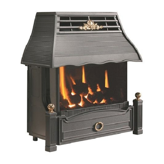
- Page 1 Emberglow COAL EFFECT BALANCED FLUE GAS FIRE Installation and Maintenance Instructions Hand these instructions to the user Model No’s FEBC00MN is for use on Natural Gas (G20) at a supply pressure of 20 mbar in G.B. / I.E. Supplied By www.heating spares.co Tel. 0161 620 6677...
-
Page 2: Table Of Contents
CONTENTS PAGE Section 1 Information and Requirements Appliance Information Conditions of Installation Fireplace surround & suitability Flue Terminal Position Shelf position Hearths Section 2 Installation of Fire Unpacking the fire Preparation of the wall Preparation of the flue hole Preparation of the flue pipes Installation of the gas supply 10-11 Securing of the combustion chamber to the wall... -
Page 3: Information And Requirements
SECTION 1 INFORMATION AND REQUIREMENTS APPLIANCE INFORMATION Main injector : (1 off) Bray Injector Elbow – size 360 Pilot Type : S.I.T.140 Series NG – size 27 Max. Gross Heat Input : 5.25 kW Min. Gross Heat Input : 2.05 kW 0.470 m 3 /hr (High) Gas Rate : 0.190 m 3 /hr (Low) -
Page 4: Conditions Of Installation
INSTALLATION REQUIREMENTS CONDITIONS OF INSTALLATION In Great Britain :- It is the law that all gas appliances are installed only by a CORGI Registered Installer, in accordance with these installation instructions and the Gas Safety (Installation and Use) Regulations 1998 as amended. Failure to install appliances correctly could lead to prosecution. -
Page 5: Flue Terminal Position
FLUE TERMINAL POSITION The minimum acceptable dimensions from the flue terminal to obstructions and ventilation openings are shown below and listed in the table It is important that the position of the flue allows the free passage of air across it at all times. The minimum acceptable space from the flue terminal to obstructions and ventilation openings are specified below (Fig. -
Page 6: Shelf Position
SHELF POSITION The fire may be fitted below a combustible shelf providing there is a minimum dis- tance of 200mm above the top of the fire and the shelf does not project more than 150mm. If the shelf overhangs more than 150mm the distance between the fire and the shelf must be increased by 15mm for every 25mm of additional overhang over 150mm. -
Page 7: Preparation Of The Wall
PREPARATION OF THE WALL The appliance and flue pipes must be installed at right angles to the mounting wall. The appliance itself should be installed vertically against a flat wall. Where an uneven wall surface is found, appropriate action should be taken to ensure that the appliance is not stressed or does not distort when installed. -
Page 8: Preparation Of The Flue Hole
PREPARATION OF THE FLUE HOLE Mark the position of the centre of the flue on the inner wall. Cut hole for outer flue pipe. There are two possible methods to achieve this, either core drill or via hammer and chisel. To core drill, proceed as follows :- Drill a pilot hole through the wall, in position as specified in figure 4. -
Page 9: Preparation Of The Flue Pipes
PREPARATION OF THE FLUE PIPES Measure the wall thickness and add on 110mm, to give the correct length of the flue. Mark this dimension onto the flue pipe, measuring from the end at which the terminal is located. Cut off surplus flue length that is not required, and remove any burrs from the edges with a burr knife or file. -
Page 10: Installation Of The Gas Supply
Fig. 6 Position of Mortar or Fire Cement Seal around Flue terminal INSTALLATION OF THE GAS SUPPLY An 8mm restrictor elbow is supplied fitted to the product for the connection of the gas supply. This elbow is situated on the right hand side of the product when viewed from the front. -
Page 11: Securing Of The Combustion Chamber To The Wall
Note : Before breaking into the gas supply a pressure drop test should be carried out to establish that the existing pipework is sound. Before making the final gas connection, thoroughly purge the gas supply pipework to remove all foreign matter, otherwise serious damage may be caused to the gas control valve on the fire. -
Page 12: Fitting The Terminal Guard
Fit the rawlplugs into the 6mm holes. Clip the cooler plate into the bottom central fixing and into the left hand and right hand mouning brackets (the same brackets used in section d) below) The mounting brackets are attached to the rear of the combustion chamber, position the product against the mounting wall and using a long philips screwdriver, secure the 2 off screws into the wall behind the product. -
Page 13: Removal & Refitting Of The Glass Frame
REMOVING / RE-FITTING THE GLASS FRAME ASSEMBLY The glass frame is held in position by hooking the top flange over the combustion chamber opening at the top as shown in Fig. 10 below. Fig. 10 Glass Frame Assembly locates over lip on top of combustion chamber lid, and drops onto flange as shown. -
Page 14: Assembling Fuel Bed And Commissioning
SECTION 3 ASSEMBLING FUEL BED AND COMMISSIONING FITTING THE FUELBED Place the fuel-bed rear section centrally in the combustion chamber as shown below in Fig. 12 Fig. 12 Retaining brackets for front coal form Retaining brackets for rear coal form Fit the front ceramic coal form in front of the burner, as shown below in Fig 13. -
Page 15: Lighting The Appliance
Refit the glass frame as detailed in section 2.8, then light the appliance as detailed in section 3.2 below. LIGHTING THE APPLIANCE IMPORTANT : IF THE BURNER IS EXTINGUISHED FOR ANY REASON YOU MUST ENSURE THAT YOU WAIT A FULL FIVE MINUTES BEFORE ATTEMPTING TO RE-LIGHT THE FIRE. Fig. - Page 16 To adjust the heat input via the touch control :- Press the “up” button to light the main burner and adjust the heat input to the maximum setting. (5.45kW heat input). Press the “down” button to reduce the heat input to the minimum setting (2.05kW heat input).
-
Page 17: Fitting The Fender
AFTER THE PILOT FLAME HAS BEEN EXTINGUISHED, IF YOU WISH TO RE-LIGHT THE APPLIANCE YOU MUST WAIT AT LEAST FIVE MINUTES BEFORE TRYING TO RE-LIGHT THE APPLIANCE. Finally, hand the Installation and Maintenance Instructions and the Users Instructions over to the customer and explain the operation of the fire. NOTE : THIS APPLIANCE IS DESIGNED TO WORK SAFELY AND EFFECTIVELY DURING ADVERSE WEATHER CONDITIONS. - Page 18 Servicing Notes Servicing should be carried out annually by a competent person such as a CORGI registered engineer. It is a condition of Flavel Fires 2 year guarantee scheme that this is carried out by a competent person i.e a CORGI registered Engineer in accordance with these servicing notes.
- Page 19 4.2.6 Swap the valve mounting plate onto the new valve by unscrewing the two M5 nuts and bolts holding it in position . 4.2.7 Re-assemble with new valve in reverse order. Removing the Battery Pack 4.3.1 Disconnect the wire from the battery pack, located at the bottom L/H/S of the combustion chamber.
- Page 20 Replacement of any other parts must be carried out by a competent person such as a CORGI registered gas installer. The part numbers of the main replaceable parts are as follows, these are available from your local Flavel Stockist, whose details can be found on the CFM Europe website, in the “stockist” section.
- Page 21 Supplied By www.heating spares.co Tel. 0161 620 6677...
Need help?
Do you have a question about the Emberglow FEBC00MN and is the answer not in the manual?
Questions and answers