Table of Contents
Advertisement
Quick Links
Advertisement
Table of Contents

Related Manuals for E+E Elektronik EE820


Summary of Contents for E+E Elektronik EE820
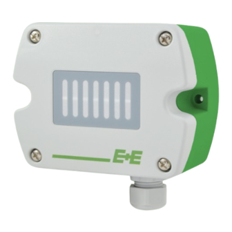
- Page 1 User Manual EE820 Sensor for Demanding Applications...
-
Page 2: Table Of Contents
General ..............................6 Electrical Connection ..........................6 4.2.1. EE820 with Cable Gland..........................7 4.2.2. EE820 with M12 Plug ..........................7 4.2.3. EE820 with conduit connection ........................8 Setup and Configuration ..........................8 Changing the Analogue Output Signal with DIP Switch ................. 8 Changing the Output Scale with EE-PCS .................... -
Page 3: General Information
The user manual may not be used for the purposes of competition without the written consent of E+E Elektronik Ges.m.b.H. and may not be forwarded to third parties. Copies may be made for internal purposes. All information, technical data and diagrams included in these instructions are based on the information available at the time of writing. -
Page 4: Safety Instructions
Failing to follow the instructions in this user manual may lead to measurement inaccuracy and device failures. ▪ The EE820 may only be operated under the conditions described in this user manual and within the specification included in chapter 7 Technical Data. ▪... -
Page 5: Environmental Aspects
Power supply and output are possible via cable gland or M12 connector (see chapter 4.2 Electrical Connection for details). For a setup deviating from default, the EE820 can be configured manually . Please refer to chapter 5 Setup and Configuration for details. -
Page 6: Dimensions
For types with cable gland, use a matching wrench for mounting the cable gland (in the scope of supply) onto the EE820 enclosure. When using EE820 with conduit connection use a flat screwdriver to knock open the blind at the top of the enclosure, carefully. Take good care to avoid damaging the electronics inside the enclosure. The conduit adapter is not included in the scope of supply. -
Page 7: Ee820 With Cable Gland
EE820 with M12 Plug The EE820 with M12 does not require any wiring inside the device. The external mounting holes allow the device to be mounted without opening the front cover. The mating M12x1 cable plug for self assembly is included in the scope of supply. -
Page 8: Ee820 With Conduit Connection
M16x1.5 opening for the cable gland shall be tightly closed using the blind plug included in the scope of supply. 5 Setup and Configuration The EE820 is ready to use and does not require any configuration by the user. The factory setup of EE820 corresponds to the type number ordered. For ordering guide please see data sheet at www.epluse.com/ee820. -
Page 9: Changing The Output Scale With Ee-Pcs
EE820 connected to a PC running EE-PCS NOTICE The EE820 may not be connected to any additional power supply when using the USB configuration adapter HA011066. To use the software for performing adjustments and changes in settings, please proceed as follows: Download the EE-PCS Product Configuration Software from www.epluse.com/configurator... -
Page 10: Maintenance And Service
6 Maintenance and Service Cover Replacement The electronics of EE820 are very well protected by the enclosure and the filter on the front cover. Thus, it is resistive even to dirty and dusty environment, In a polluted environment, the filter on the EE820 front cover might get clogged in a long run. Longer response time indicates a clogged filter. -
Page 11: Technical Data
User Manual EE820 8 Technical Data Measurands Measurement principle Dual wavelength non-dispersive infrared technology (NDIR) Measuring range 0...2 000 / 5 000 / 10 000 ppm Accuracy @ 25 °C (77 °F) and 1 013 mbar (14.7 psi) 0...2 000 ppm < ±(50 ppm + 2 % of measured value) 0...5 000 ppm < ±(50 ppm + 3 % of measured value) 0...10 000 ppm... -
Page 12: Conformity
User Manual EE820 9 Conformity Declarations of Conformity E+E Elektronik Ges.m.b.H. hereby declares that the product complies with the respective regulations listed below: European directives and standards. UK statutory instruments and designated standards. Please refer to the product page at www.epluse.com/ee820... - Page 13 User Manual EE820 Sensor for Demanding Applications | 13...
- Page 14 E+E Elektronik Italia S.R.L. T +39 02 2707 86 36 info.it@epluse.com E+E Elektronik Korea Ltd. T +82 31 732 6050 info.kr@epluse.com E+E Elektronik Corporation T +1 847 490 0520 info.us@epluse.com Version v1.7 | 06-2023 © Copyright E+E Elektronik Ges.m.b.H. | Modification rights reserved.
Need help?
Do you have a question about the EE820 and is the answer not in the manual?
Questions and answers