
Subscribe to Our Youtube Channel
Related Manuals for Dent ELITEpro XC

Summary of Contents for Dent ELITEpro XC
- Page 1 Operator’s Guide ELITEpro XC ™ ELOG™ 15 Software ™ ™ ELITEpro XC /ELOG March 1, 2017...
- Page 2 You now own one of the world’s most versatile, accurate, feature-rich, and lowest priced power/energy loggers, the ELITEpro XC™. The ELITEpro XC logger contains many features, some of which enable you to measure data across multiple platforms, view and graph real-time data, and retrieve data remotely.
-
Page 3: Table Of Contents
Creating and Using the Logger Setup Tables ................. 38 Create a New Setup Table ....................... 38 Open an Existing Setup Table on Your PC ................39 Retrieve an Existing Setup Table from the ELITEpro XC ............40 Configure the Setup Table ....................... 41 Data Logging Controls ......................42 Start Options ........................ - Page 4 Logger Clock Sub-Menu ....................80 Edit Logger Description Line ..................... 81 Logging ON/OFF ........................ 81 Clear Logger Sub-Menu..................... 82 Tools Menu ..........................83 PC Setup ..........................83 Update Logger Firmware (ELITEpro XC only) ..............84 Restore Hidden Messages....................84 DENT Instruments ELITEpro...
- Page 5 Using The 2-Watt Element (2 Ct) Method On A 3-Wire Delta Service ........99 Using The 3-Watt Element (3 Ct) Method On A 3-Wire Delta Service ........100 Appendix C—Troubleshooting ELITEpro XC Driver Installation ........... 102 Appendix D—AUTOPOLL: Unattended Data Collection ............... 106 AutoPoll Menu Options ......................
- Page 6 USB (Standard) ........................117 Ethernet LAN (Standard) ....................... 118 Wi-Fi and Wireless Access Point Connection (Optional) ............121 ELITEpro XC as its own Access Point ................121 ELITEpro XC Connected to a Wireless Network .............. 123 Accessing the ELITEpro ....................125 Troubleshooting Wi-Fi Connections ................
-
Page 7: Introduction
The measurements are stored in on-board, non-volatile memory in a time series format at an interval selected by the user. The ELITEpro XC can be mounted anywhere with its magnetic back and is small enough to be secured inside the electrical panel. -
Page 8: Elitepro Xc Safety Summary And Specifications
4RH8 E186827 The ELITEpro XC is an Over-Voltage Category III device. Use approved rubber gloves with mechanical protection and goggles when operating the device. CAUTION: This LOGGER may contain life-threatening voltages. QUALIFIED PERSONNEL MUST disconnect all high voltage wiring before using or servicing the LOGGER. - Page 9 CT-RXX-1310-U (RōCoil), CTRXX-A4-U (RōCoil), CT-CON-1000-X, CT-CON-0150EZ-X and the CT-SRL-XXX. The use of any other CT will invalidate the UL Listing of the ELITEpro XC. Pulse: Use only "dry contact" non-energized pulse inputs (ELITEpro SP only). Use of energized pulse initiators can cause damage to the logger and a potential shock hazard to the user.
- Page 10 Battery Life: The lithium battery is only used to maintain the date and clock settings during power failure and has a life expectancy of greater than 10 years. Contact DENT Instruments for service. No accessories are approved for use with the ELITEpro XC other than those specified in the DENT Instruments product literature and price sheets.
-
Page 11: Elitepro Xc Résumé De Sécurité Et Spécifications
600V. Le dépassement de cette tension peut causer des dommages à l'appareil et du danger pour l'utilisateur. Utiliser toujours le potentiel transformateur (PT) pour des charges de plus de 600V. Le ELITEpro XC est un appareil à 600 V de surtension de catégorie III. Se débarrasser de correctement. - Page 12 N’utilisez pas d'autres TC. Utilisez seulement des TC shuntée avec une puissance maximale 333mV. Un sérieux risque de décharge électrique et des dommages à l'enregistreur peut se produire si des TC pas shuntée sont utilisés. Utiliser seulement les CTs des DENT Instruments suivants qui sont énumérés jusqu'au 600V/CATIII.
- Page 13 Il n'y a aucun entretien requis avec le ELITEpro XC. Respectez les points suivants: Nettoyage: Aucun agents de nettoyage, y compris l'eau, doit être utilisé sur le ELITEpro XC. Espérance de Vie de la Batterie: La pile au lithium est utilisée uniquement pour maintenir les paramètres de date et d'heure en cas de coupure de le courant et a une espérance de vie de plus de 10...
-
Page 14: Elitepro Xc Technical Specifications
Introduction ELITEpro XC TECHNICAL SPECIFICATIONS Specification Description Memory 16 MB non-volatile Single Phase-Two Wire, Single Phase-Three Wire, Three Phase-Four Wire (WYE), Service Types Three Phase-Three Wire (DELTA), DC Systems (solar/battery). Voltage Channels 3 channels, CAT III, 0-600 VAC (line-to-line) or 600 VDC Current Channels 4 channels, .67 VAC max, +/- 1 VDC max;... - Page 15 Windows® 7 (32 or 64 bit), Windows® 8, Windows® 10 or Vista (32 or 64 bit) Processor Pentium Class 1 GHz or more recommended Hard Drive 50 MB minimum available Communications Port One USB port required for logger connection and ELOG software installation DENT Instruments ELITEpro...
-
Page 16: Elitepro Xc Connections
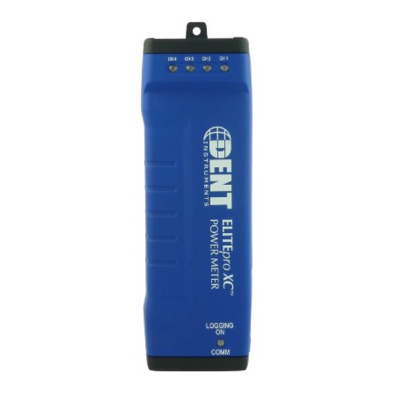
ELITEpro XC CONNECTIONS USB Connection Logging On/Comm LED ™ PhaseChek LEDs Terminal Block for Analog Input Connections Optional Wi-Fi—External 5 dbi antenna Ethernet connection Power In/Out Magnetic Mounting Feet CT Connections Voltage Lead Connections ELITEpro XC Top End View DENT Instruments ELITEpro... -
Page 17: Dent Instruments Warranty Statement
Rev 4/9/2015 DENT Instruments, Inc. promises buyer that any product sold by DENT Instruments, Inc. shall be free from material defects in design, materials, or manufacturing for the period shown on the current datasheet for that product beginning from the manufacture date; provided, however, that the warranty shall not extend to ordinary wear and tear, or to normally replaceable components (e.g., batteries and humidity sensor... - Page 18 Before calling, remember that many questions are answered in the Operator's Guide for your product. Furthermore, there is extensive product information on the website. In the event that you have a problem with your DENT product that you cannot resolve, please note the following information.
-
Page 19: Prepping & Using The Elitepro
PREPPING & USING THE ELITEPRO IMPORTANT: DO NOT CONNECT THE ELITEpro XC TO YOUR COMPUTER UNTIL YOU HAVE INSTALLED ELOG 15 Install the ELOG Software on the Computer Complete this step prior to installation and ascertain that communication between the ELITEpro XC and PC is established before going into the field. -
Page 20: Mount The Elitepro Xc
AVERTISSEMENT! ENLEVEZ L'ENREGISTREUR DE TOUTES LES SOURCES DE TENSION AVANT DE MONTER. 1) Mount the ELITEpro XC using the black tab on the end of the case containing the PhaseChek and voltage lead connections. Use a screw to securely mount the ELITEpro XC near a dedicated circuit disconnect breaker. -
Page 21: Elitepro Xc Connections
Prepping & Using the ELITEpro “Roll” the device, as seen below. 2) Mark the dedicated circuit as the disconnect for the ELITEpro XC. ELITE XC C ONNECTIONS The ELITEpro XC has the following connections: Four current transformers (CTs). ... -
Page 22: Complete The Wiring Connections
X (200A Midi). The use of any other CT will invalidate the UL Listing of the ELITEpro XC. 1) Connect the CTs to the channel(s) on the ELITEpro XC labeled CH 1, CH 2, CH 3 and CH 4. The CT leads need to be connected to the terminal block using a small screwdriver. -
Page 23: Connecting Split-Core Style Millivolt Cts To A Load
CT rating listed on the CT data sheet. 3) Carefully re-connect the removable leg while ensuring the CT core alignment matches. The conductor should be in the inside of the CT window. Repeat Steps 1-3 if you are using more than one CT. DENT Instruments ELITEpro... - Page 24 CT label, it should correspond to the appropriate phase as shown in Channels 2, be pointed toward the load. 3, and 4 in the ELOG setup table. Otherwise, use the instructions printed on the CT. DENT Instruments ELITEpro...
-
Page 25: Connecting Rōcoil Cts To A Load
“S” shield terminal that is part of the CH 4 connector. This reduces interference and improves accuracy of the CT. Positive Negative Shield Shield Wires from DENT RōCoil CTs connected to ELITEpro XC Connecting RōCoil CTs to an ELITEpro XC DENT Instruments ELITEpro... -
Page 26: Voltage Connections
Typical uses might include logging ambient temperature, building temperatures, solar insolation, tank pressures, duct flows, etc. The ELITEpro XC has four analog input channels that can be configured for voltage or current input used in any combination among channels. The limiting specifications for analog input are shown below. - Page 27 0–30* VDC single ended, non-isolated NOTE: The ELITEpro XC can measure input voltages up to 30.0 volts. The polarity protection circuitry however can only withstand 15 volts of reverse-applied polarity without permanent damage to the meter. The maximum allowable current flowing into the analog input terminal is 23 mA.
-
Page 28: Current Loop Connection
For this reason it is imperative that the ELITEpro XC be connected as the last component in the current loop rather than the first if multiple channels are used. Best practices are to use a single power supply for all sensors to reduce the occurrence of ground loop current between supplies. -
Page 29: Voltage Connection
Sensors having four terminals are also popular and are simply connected to the meter by observing the indicated polarity between sensor and meter. Power Supply Sensor Separately Excited Current or Voltage Loop Configuration DENT Instruments ELITEpro... -
Page 30: Power In/Out Connection
To power the ELITEpro XC using an external supply contact DENT Instruments for an appropriately-rated power supply. The ELITEpro XC can also supply 6V DC at up to 200mA to an external device when the ELITEpro XC voltage leads are connected to mains power between 80 and 600 VAC. IGITAL... - Page 31 For example, if 22 is entered in the Scale field and kWh is selected for the Value, then each pulse generated by the meter is equal to 22 kWh on the selected Power Channel. NOTE: The maximum output rate is five (5) pulses per second, or 5Hz, with a maximum current of 75mA and 30V DC. DENT Instruments ELITEpro...
- Page 32 1:05:01 PM (5 minutes and 1 second after the hour), logging AND pulse output accumulation will NOT start until 1:10:00 PM. 5) Upon completion of your pulse output measurements, disconnect the wires of your device. DENT Instruments ELITEpro...
-
Page 33: Connecting The Usb Cable
COM port of the ELITEpro XC. If a USB cable is used inside an electrical panel, it must be rated to the appropriate voltage or wrapped in an appropriately-rated insulating sleeve. The DENT-supplied cable does not meet this requirement without an insulating sleeve. -
Page 34: Other Communication Connections
NOTE: If an antenna is used inside an electrical panel, it must be at least 2" away from any live wiring or bus bars. An internal Bluetooth antenna is an optional connection. External Antenna— for WiFi (optional) Ethernet port Communication Connections DENT Instruments ELITEpro... -
Page 35: Communicating With The Elitepro Xc
Communicating with the ELITEpro XC 1) Plug the USB cable into the logger and the PC. ELOG 15 should auto-launch and connect to the ELITEpro XC automatically. If not, double-click the ELOG icon on the PC desktop. The ELOG window opens,... - Page 36 The Logger Connection information displays along the bottom of the window, providing a status message as the computer connects to the ELITEpro XC. Simultaneously, the logger’s COMM LED will begin to flash. ELOG fills the information fields of the Logger Connection...
-
Page 37: Terminating The Elitepro Xc To Computer Connection
8) Use Logger > Display Real-Time Values to verify installation. ELITE ERMINATING THE OMPUTER ONNECTION Select Logger > Communication > Terminate Connection to end the connection between the computer and the ELITEpro XC -or- Use the Disconnect speed button to quickly terminate the connection DENT Instruments... -
Page 38: Best Practices
The ELITEpro XC requires that it be configured for use by first creating a “Setup Table” file and then loading the file into the meter. The ELITEpro XC is a flexible meter that can monitor a wide variety of parameters over a wide range of currents, voltages and service types. This requires that you determine what is recorded and at what intervals. -
Page 39: Open An Existing Setup Table On Your Pc
Best Practices 2) Select ELITEpro XC from the drop-down menu. 3) Click OK. PEN AN XISTING ETUP ABLE ON Existing setup tables on the computer can be opened, modified, and saved. 1) Select File > Open to display the Open dialog box. -
Page 40: Retrieve An Existing Setup Table From The Elitepro Xc
ETRIEVE AN XISTING ETUP ABLE FROM THE Existing setup tables on the ELITEpro XC can be retrieved once the computer and the logger are connected and communicating. Select Logger > Retrieve Logger Setup Table. The setup table stored in the logger is retrieved and displayed, with the name of the file above the ELOG menu bar. -
Page 41: Configure The Setup Table
Best Practices ONFIGURE THE ETUP ABLE The setup table consists of several sections where the attributes of the ELITEpro XC are defined. Logger Type Setup Table Name Data Interval Line Frequency ELITEpro XC is the default Enter a name for the The default integration Auto, 60 Hz, or 50Hz. -
Page 42: Data Logging Controls
The feature is dynamic so that any time any parameter in a setup table affecting the memory duration is changed, the Memory Capacity field is updated, providing the (new) length of time the logger’s memory will last. The ELITEpro XC has 16 MB internal non-volatile memory. DENT... -
Page 43: Quick Setups
Best Practices UICK ETUPS The Quick Setups section of the window provides four buttons to quickly configure the ELITEpro XC. 1) Click the Quick Setup button that represents your monitoring scenario. Each button opens the CT Selection dialog window. See ELOG Quick Setup Wiring Diagrams within this section for more detail. - Page 44 3) Click OK. 4) Check the Enable THD checkbox if you want total harmonic distortion to appear as a percentage in the Data File Summary report. Selecting this option automatically populates any required value field necessary to determine distortion. DENT Instruments ELITEpro...
-
Page 45: Physical Power Channels
Clicking this button displays a wiring diagram showing how to connect the CTs and the voltage leads of the ELITEpro XC corresponding to the selected setup. The diagram can be printed and carried into the field for easy reference during installation. Refer to ELOG Quick Setup Wiring Diagrams for detailed information of each Quick Setup option. - Page 46 AUTION Transformer) is not used on service voltages greater than 600V, the ELITEpro XC may overheat (or worse) causing irreparable damage and extreme danger to the user. The Recorded Values of a power channel tell the logger what parameters you wish to record and can be configured by selecting any combination of Volts, Amps, power (kW), volt-amps (kVA), power factor (PF), and volt-amps-reactive (kVAR) as desired for each channel you turned on.
- Page 47 AC voltages greater than 600V. The default is 1.000. Type This is the type of CT connected to the Choices are: MilliVolt or RōCoil. ELITEpro XC Amps Depends on the type of CT selected. Displays the value entered in the CT Size screen. Phase Shift Compensate for CT Phase Shift with this setting.
-
Page 48: Calculated Power Channels
2) Under Calculated Power Channels, turn on the channel by selecting Power Sum from the Channel 5 menu. Perform the same function for Channel 6, if desired. 3) Enter a name for the Calculated Power Channels (optional). 4) Select the Physical Power Channels to be added together in the Combine Channels box. DENT Instruments ELITEpro... -
Page 49: Analog Output Channels
The following graphic is an example of a Setup Table for a 3-phase 4-wire connected load using a Calculated Power Channel with Combine Channels 1, 2, and 3 selected to optimize memory usage on the ELITEpro XC. NOTE: The Recorded values listed to the right of the Current Transformers section on the Setup Table are not shown in this graphic. -
Page 50: Send A Setup Table To The Logger
OGGER When you’ve finished selecting the configuration options, the setup table needs to be sent to the ELITEpro XC. 1) After connecting to the logger, click on one of the SEND SETUP TABLE to Logger command buttons on the Setup Table screen. -
Page 51: Save A Setup Table On The Computer
Typical Setup. This button displays a schematic Monitoring can begin once the ELOG software is graphic of how to connect the ELITEpro XC to a configured and the ELITEpro XC is connected. The load. The schematic can be printed and carried... -
Page 52: Led Diagnostics
COMM—C OMMUNICATIONS The ELITEpro XC COMM LED flashes different colors (green, blue, red) to indicate that the logger is connected, logging information, and communicating with the computer. Which color indicating which condition is dependent on the version of firmware being used by the logger. However; one color always indicates the same condition: green will flash approximately once per second when the ELITEpro XC is logging and communicating with the computer. -
Page 53: Power Measurement-Connecting Sensors & Configuring Channels
WARNING: Use of this device in a manner for which it is not intended may impair its means of protection. Do not exceed 600 VAC voltage inputs! When connecting the ELITEpro XC to an AC load, follow these steps in sequence to prevent a shock hazard. -
Page 54: Wiring Label Conventions
IEC 61010-1 standard by other Nationally Recognized Testing Laboratories (NRTLs), the use of any other CT will invalidate the UL Listing of the ELITEpro XC. This is simply a decision made by UL, and in the opinion of DENT Instruments, all CTs provided are equally safe to use. - Page 55 1000A 600A Current Ratings of CTs Available from DENT Instruments All of the CTs in the table are available from DENT Instruments. ? You can extend These are internally shunted CTs (333.3 mV output) which the leads for a RōCoil up to 100...
-
Page 56: Ct Selection Examples
CT value to be used in the Logger setup table, multiply the utility CT ratio by the ELITEpro XC CT size (e.g. if the utility CT is 4000:5 and the DENT CT is 50A use (4000/5) x 50 = 40,000 for the value of the CT in the logger Setup Table. - Page 57 Voltage Lead Connections ELITEpro XC End View of CT and Voltage Lead Connections 2) Apply the CTs to the phases being monitored observing proper CT orientation. 3) If there is an arrow on the CT label, the label should point towards the load. Otherwise, use the instructions printed on the CT, for example: “This Side Toward Load.”...
-
Page 58: Elog Quick Setup Wiring Diagrams
Clicking this button displays a wiring diagram that corresponds to the selected setup, showing how to connect the CTs and the voltage leads of the ELITEpro XC. The diagram can be printed and carried into the field for easy reference during installation. - Page 59 Best Practices Typical Single Phase, 3-Wire Setup Diagram DENT Instruments ELITEpro...
- Page 60 Best Practices Typical 3 Phase, 3-Wire Delta Setup Diagram DENT Instruments ELITEpro...
- Page 61 Best Practices Typical 3 Phase, 4-Wire Wye Setup Diagram DENT Instruments ELITEpro...
-
Page 62: Using The Elog Software
UTTONS The ELOG speed buttons enable users to quickly navigate between commonly used functions. For ™ example, to connect between the computer and the ELITEpro XC over a serial or Bluetooth connection, use the button instead of the menu commands Logger > Communication > Connect Via... The button toolbar can be toggled on and off by selecting the View >... - Page 63 Setup PC: Quickly access computer setup configurations Create Graph: Create a graph from an open data file, available under the Data dropdown menu UnZoom Graph: Use to back out of an expanded graph Help Topics: Opens the ELITEpro XC and ELOG Manual DENT Instruments ELITEpro...
-
Page 64: Keyboard Shortcuts
The File menu has options similar to that of other software products, such as a Print Setup and a list of recently accessed files. Descriptions of other options are below: File > New creates a new file. There are four file types that are available for ELITEpro XC ™ loggers. ... - Page 65 Setup Table File—If you are not already connected to a logger, ELOG prompts you to select the logger type (ELITEpro XC) for which you want to create a new Setup Table. If you are already connected to a logger, ELOG assumes that the Setup Table you are about to create is for the logger type to which you are connected.
-
Page 66: Edit Menu
The Connection Window appears at the bottom of the screen during connection to a logger and provides information about the logger, communication port, baud rates, etc. Refer to Communicate with the ELITEpro XC in Section 1 for more information. The Toolbar option enables/disables buttons under the main menu. -
Page 67: Logger Menu
Best Practices OGGER The Logger menu is used to configure the ELITEpro XC, view channel data in real time, download logger data, and set communication parameters. Graphing and analysis functions are found under the Data menu. Communication Sub-Menu Use the options on the Communication sub-menu to establish a connection between the computer and the ELITEpro XC. - Page 68 Best Practices The options on the Communication sub-menu determine how communication with the ELITEpro XC is established and where logger information is saved. PC Setup Use this option to set the default location for data, setup tables, and logger files. You can also set the default PC communication ports here.
- Page 69 Number you enter in the Network Connect dialog box to connect via Ethernet with ELOG. Select Update Logger to send the new Ethernet Setup to the logger or Cancel to close the window without updating the logger. See Appendix F—Detailed Connection Options. DENT Instruments ELITEpro...
- Page 70 Select Update Logger to send the new Wi-Fi Setup to the logger or Cancel to close the window without updating the logger. Appendix F—Detailed Connection Options. Logger Web/Mobile App LoginPassword Use this option to create a password for accessing your Wi-Fi from the web or a mobile device. Appendix F—Detailed Connection Options. DENT Instruments ELITEpro...
- Page 71 AutoPoll is a standalone Windows program (supplied with ELOG) that may be used for unattended and automatic data retrieval from a number of remote loggers where the PC connects to the loggers. A complete description of AutoPoll can be found in Appendix D— AUTOPOLL: Unattended Data Collection. DENT Instruments ELITEpro...
-
Page 72: Retrieve Data From Logger
Check the Append New Data To Existing Data File box. The name of the dialog box changes to Select a Data File to Append Data To. Select the file to which you wish to add the data. DENT Instruments ELITEpro... - Page 73 The data is saved to the folder specified in Tools > PC Setup > Data Files Saved To: unless changed in the Select a Directory and A Name… window. The default data folder is C:\Users\UserName\Documents\DENT\ELOG\Data. To view a data file, use Data > Open Data File and then select the desired file.
-
Page 74: Display Real-Time Values Sub-Menu
How much memory has been used and how many days the memory has remaining before filling The logger clock’s current date and time Whether or not the data logging is turned on Type of memory: Linear (Stop When Full) or Ring (Continuous) DENT Instruments ELITEpro... - Page 75 This is due to differences in scaling and to reduce clutter on the graph. For example, you could display kW from four channels simultaneously but not a kW and a KVAR even if it is from the same channel. 2) Select a parameter to chart. DENT Instruments ELITEpro...
- Page 76 Use Set X and Y Axis to set the scaling and the line type (e.g., linear or logarithmic). You can also set the amount of time data is graphed. This can vary from 1 second to more than 18 hours (65,000 seconds). Note that the X-axis scaling is only approximate. DENT Instruments ELITEpro...
- Page 77 The first capture is by default channel 1, but you can select different channels (logging off or on) to view, and copy the waveform to the clipboard for pasting into other programs or for printing. DENT Instruments ELITEpro...
- Page 78 63 harmonics. The Waveform Values section provides summary statistics for the overall voltage and current waveforms. This includes the RMS value, THD, Peak values, Crest Factor, Line Frequency, and K-Factor. DENT Instruments ELITEpro...
- Page 79 When a logger is connected with Power 5 and/or Power 6 Channels on, select Logger > Display Real- Time Values > Realtime Peak Demand to request a report showing peak demand and totalizer values directly from the logger instead of from a data file. DENT Instruments ELITEpro...
-
Page 80: Retrieve Logger Setup Table
Use this option to manually set the date and internal clock. The date format defaults to what is used by the time settings on your PC (mm/dd/yy or dd/mm/yy) and the clock uses a 24-hour format. Synchronize Time To Match PC Use this option to read the computer clock and automatically update the logger. DENT Instruments ELITEpro... -
Page 81: Edit Logger Description Line
This option allows you to change the user-defined, one line description stored in the logger. The Description Line can help identify the specific logger after the logger is retrieved from the field. Logging ON/OFF This option starts or stops data collection. DENT Instruments ELITEpro... -
Page 82: Clear Logger Sub-Menu
Clear ONLY Peak KW, KVAR, and KVA Demand… Clears only the peak demand values, kW, kVA, & kVAR. Once deleted, it cannot be retrieved. Clear ONLY KWh, KVARh, KVAh, etc. Totals… Clears only cumulative totals. Once deleted, it cannot be retrieved. DENT Instruments ELITEpro... -
Page 83: Tools Menu
PC Setup Selecting Tools > PC Setup allows you to configure the computer connected to the ELITEpro XC. It is also where you set the default file storage folders. The Data Files Saved To: field displays the folder selected for storage. Click Browse to set the default folder in which data files are saved. -
Page 84: Update Logger Firmware (Elitepro Xc Only)
The Enable Auto Launch of ELOG checkbox defaults to enable the Auto Launcher, which launches ELOG (if not already open) when an ELITEpro SP or ELITEpro XC or newer ELITEpro is connected to a USB port. When not checked, it disables the feature and hides the Auto Launcher icon in the system tray. -
Page 85: Data Menu
Best Practices Data retrieved from an ELITEpro XC can be opened, graphed, exported, or analyzed. NOTE: These are the only options available on the Data menu when first accessed. The other options appear after a data file is open. Create New Graph 1) When a data file is open, Data >... - Page 86 Use current graph attributes—uses the attributes selected for the last graph. 7) Click Next. If the Use multiple Y axes checkbox was selected the Select Y-Axis Assignments window displays in order for you to assign parameters to the Y axes. DENT Instruments ELITEpro...
- Page 87 Export section to choose a graph View > UnZoom, Ctrl+U, or click the type. Choose a location to export the graph in the Export Destination area. Set the size of the exported Zoom speed button. graph in the Export Size fields. DENT Instruments ELITEpro...
-
Page 88: Graph Options
The values appear to the right of the graph where the graph labels are also shown. If desired, by unchecking the Show analysis values box, the values will not be shown (or printed) on the graph. DENT Instruments ELITEpro... -
Page 89: Retrieve Data From Logger
To view the data from a spreadsheet program follow these steps: 1) Retrieve the data from the logger using Logger > Retrieve Data from Logger or Data > Open Data File. 2) Select File > Export Data File. The Select a File for Export dialog box displays. DENT Instruments ELITEpro... -
Page 90: Import Csv File
5) Use the File > Open command in the spreadsheet and select All Files in the Files of type drop-down list. 6) Open the .csv data file from the folder you specified, for example: C:\Users\UserName\Documents\DENT\ELOG\Data Import CSV File This feature imports a previously saved .csv file into ELOG 15 for use. Select the file you wish to import, and then choose Open. -
Page 91: Data File Statistics
Provides the start and end times of the data, file name in the computer, and summary statistics for each channel and parameter that was recorded by the logger. The Data File Summary is opened in Microsoft Notepad™ and can be edited, saved, printed and/or moved into another report. DENT Instruments ELITEpro... - Page 92 Provides a report of peak demand information on the channels used for collecting the data. The Peak Demand report is opened in Microsoft Notepad™ and can be edited, saved, printed and/or moved into another report. NOTE: Calculations for peak demand are only available when Channels 5 and 6 are on. DENT Instruments ELITEpro...
-
Page 93: Analyze A Selected Data Range
Click File to open Windows Notepad™. The maximum value and time of occurrence is shown with the date range for the data selected for analysis. As with the Data File Summary, the data contained in the Notepad file may be edited, saved, printed or moved into another program for reporting generation. DENT Instruments ELITEpro... -
Page 94: Extract A Range Of Data
(first column in the data file). Click Ok the right mouse button to select your to create the selected range. options. DENT Instruments ELITEpro... -
Page 95: Check Data For Errors
"Fill Missing Records" detects gaps in the time sequence of the data shown, and fills the missing records with 0 values. This feature is useful when data logging has paused (such as during a power outage) and there are gaps in the time stamp records. DENT Instruments ELITEpro... -
Page 96: Appendices
IRMWARE PDATES You can check the firmware version of your ELITEpro XC from the Tools menu. Select Tools > Update Logger Firmware. The Firmware Update dialog box displays. No update is required if your firmware File version and Logger Version are the same. -
Page 97: Appendix B-Unusual Metering Systems
Appendices Appendix B—Unusual Metering Systems “W ” (R HASE ELTA WITH A 3 Phase DELTA with a “Wild” (Red) Leg Configure the Setup Table as follows: DENT Instruments ELITEpro... -
Page 98: 2-½ Element Meters
2-½ Element Meters Configure the Setup Table as follows: *The CT on channel three of the ELITEpro XC is placed on the L2 phase and is backwards. Note that the Ch3 CT is jumpered in parallel into Ch4 of the logger. -
Page 99: Using The 2-Watt Element (2 Ct) Method On A 3-Wire Delta Service
PT ratio is. ***Set the CT value that is true for the CT connected to the ELITEpro XC. Again, because the 2 ½ element method is most often used in high voltage applications, there will be high voltage CTs present. -
Page 100: Using The 3-Watt Element (3 Ct) Method On A 3-Wire Delta Service
Volts X Amps and VA would contain harmonic content. The other is Displacement Power Factor that uses the Power triangle PF=W/SQRT (W^2 + VAR^2) which does not contain harmonic content. The ELITEpro XC displays and records displacement Power Factor. DENT... - Page 101 It is very similar to the 3-phase, 4-wire WYE connection. Use a CT on each phase and connect the three ELITEpro XC voltage wires to each phase. The neutral wire should then be connected to earth ground. The Setup table should look just like that of the 4-wire WYE setup. See ELOG Quick Setup Wiring Diagrams in Section II.
-
Page 102: Appendix C-Troubleshooting Elitepro Xc Driver Installation
Appendices Appendix C—Troubleshooting ELITEpro XC Driver Installation If you have connected the ELITEpro XC to a computer via the USB cable and the driver fails to install, follow these steps to correct the problem. 1) Go to the Device Manager by right-clicking My Computer in the Start Menu and selecting Properties. - Page 103 Appendices Windows XP 3) Look for the ELITEpro XC listed in the Device Manager Window: DENT Instruments ELITEpro...
- Page 104 5) In the Hardware Update Wizard, select Install from a list or specific location (Advanced) and click Next. 6) In the next window, select Search for driver software in this location: and Include Subfolders in the search. Click Browse and locate the ELITEpro XC driver folder in the ELOG directory. DENT Instruments...
- Page 105 Appendices 7) Click Next> and the ELITEpro XC driver will install. In the event that you receive a warning dialog box from Microsoft, click Continue to proceed. 8) Unplug the ELITEpro XC and plug it back in. ELOG 15 should launch and automatically connect to the ELITEpro XC.
-
Page 106: Appendix D-Autopoll: Unattended Data Collection
Opens a new empty Logger List. Open The Open function is very similar to the New command except it assumes that a Logger List is already stored somewhere on the computer disk. Logger list files have an .lst extension. DENT Instruments ELITEpro... -
Page 107: Edit Menu
Exits and closes the AutoPoll program. Edit Menu Add Logger Adds a new logger to a logger list Remove Logger Removes a selected logger from a logger list Cut, Copy, Paste Standard Windows commands. DENT Instruments ELITEpro... -
Page 108: View Menu
Cancel Today's Calls This feature deletes all calls scheduled for the day and they are NOT called later. DENT Instruments ELITEpro... -
Page 109: Tools Menu
Lists may be selected is set here. The Direct Connect section shows the port and baud rate of the connected ELITEpro XC. The Modem Connect section displays connection information about legacy products. Enter an amount of minutes into the Final Delay Time box to retry data retrieval one last time. -
Page 110: Log File
AutoPoll Log. An excerpt example of the Log is shown below: At the end of each call, a dashed line is added to the bottom of the file to separate calling sessions. - DENT Instruments - AutoPoll Event Log File... -
Page 111: Understanding The Logger Lists
Appendices The file created is labeled autopoll.log and is automatically saved to whatever folder contains the ELOG application program (typically C:\Users\UserName\Documents\DENT\ELOG\Data). The folder where the file is saved may not be changed except by moving the ELOG application too. As subsequent polling sessions are completed, the autopoll.log file is automatically updated and the new contact reports are appended to the existing .log file. -
Page 112: Configuring A Logger List
For a network connection enter the IP address of the logger and the port number (default is 3001). Data File Path: is the location of the folder where data files retrieved from the logger are saved. DENT Instruments ELITEpro... -
Page 113: Entering Autopoll Tasks
PC Setup for that logger. If the data file has been moved or this is the first time the logger has been read and Append New Data is selected, then AutoPoll will download the entire memory of the logger. DENT Instruments ELITEpro... -
Page 114: Call Interval
Use the Weekly Times To Call box to select the days and the hour (hh) and minute (mm) the calls are to be made. Only one call per day is permitted but they can be at different times on different days. DENT Instruments ELITEpro... -
Page 115: Appendix E-Calculated Power Channel Formulas
See kWh (System) WYE notes. # of samples in an hour kW System Measurement calculation information Apparent PF System is provided for reference only. kVA System kW System Displacement PF System SQRT [(kW System) + (kVAR System) DENT Instruments ELITEpro... -
Page 116: Delta Configuration: L1-L2 And L3-L2
+ (System kVAR) kVAh (System) SQRT [(System kW) + (System kVAR) Same as Displacement PF System Apparent PF System below. Cannot calculate APF for delta loads. kW System Displacement PF System SQRT [(kW System) + (kVAR System) DENT Instruments ELITEpro... -
Page 117: Appendix F-Communication Options
2) ELOG 15 should launch automatically and connect to the logger. If it does not, click on the icon on the computer desktop. 3) The ELITEpro XC should automatically connect to the PC. If it does not, choose the correct location from the Friendly Ports™ drop-down menu. For more information regarding Friendly Ports™, see Communicate with the ELITEpro XC in Section 1. -
Page 118: Ethernet Lan (Standard)
Ethernet port 1) Configure the EXC for use on the network. First connect the USB cable to a USB port on your computer, inserting the other end into the USB port on the ELITEpro XC. (Hint: Look for this USB symbol: ) If a USB cable is used inside an electrical panel, it must be rated to the appropriate voltage or wrapped in an appropriately rated insulating sleeve. - Page 119 Appendices 3) The ELITEpro XC should automatically connect to the PC. If it does not, choose the correct location from the Friendly Ports™ drop-down menu. For more information regarding Friendly Ports™, see Communicate with the ELITEpro XC in Section 1.
- Page 120 Selection dialog box. Look for the serial number of the logger to determine which connection point is yours. The logger’s serial number can also be found on the back of the logger. Select your logger in the Logger Selection dialog box and click OK, and then OK again in the Network Connect window. DENT Instruments ELITEpro...
-
Page 121: Wi-Fi And Wireless Access Point Connection (Optional)
1) Set up the logger for Access Point connection. Connect the USB cable to a USB port on your computer, inserting the other end in the USB port on the ELITEpro XC (Hint: look for this USB symbol: ). - Page 122 7) Click Save Changes in the Logger Wi-Fi Setup dialog box. ELOG updates the Wi-Fi settings and prompts you to click OK in order to reset the ELITEpro XC. NOTE: After the blue COMM LED on the ELITEpro XC device stops blinking, use the ELOG command Logger >...
-
Page 123: Elitepro Xc Connected To A Wireless Network
Wireless Network An ELITEpro XC with a Wi-Fi module may also be connected to a local area network (LAN) through a wireless access point or wireless router. To set up the logger it must first be configured via a USB connection to a PC running ELOG and may require assistance from someone familiar with the network you want to connect to. - Page 124 1) Set up a Wi-Fi logger for connection to a wireless network first. Connect the USB cable to a USB port on your computer, inserting the other end in the USB port on the ELITEpro XC (Hint: look for this USB symbol: ).
-
Page 125: Accessing The Elitepro
3001 (not supported by the mobile app). 9) Click Save. ELOG updates the Wi-Fi settings and prompts you to click OK in order to reset the ELITEpro XC. NOTE: After the blue COMM LED on the ELITEpro XC device stops blinking, use the ELOG command Logger >... - Page 126 App Login Password dialog box displays. b) Open a web browser on the device that will communicate with the ELITEpro. c) In the Address box of the browser, enter the IP Address of the ELITEpro XC as previously configured. For example: http://192.168.1.1.
-
Page 127: Troubleshooting Wi-Fi Connections
Using the ELITEpro Mobile App to connect to the ELITEpro XC Access Point The ELITEpro Mobile App provides access to any ELITEpro XC or SP meter. Use this app in a remote setting, such as your car or office, to access data from an ELITEpro meter. Once connected with the meter, you can see real-time data to verify connections and read voltage, current, kW, kVA, PF, kVAR, and other parameters. -
Page 128: Elitepro Mobile App (Optional)
Connections must be configured initially via USB by users with knowledge of Windows Bluetooth wireless technology enabled products. To make a Bluetooth connection from a PC to an ELITEpro XC both devices must have a Bluetooth module. Most PCs, including laptops, do not have Bluetooth and it may be necessary to purchase a Bluetooth dongle (usually a plug-in USB device) and add it to the PC. - Page 129 1) Click Add a Device. You should then see a list of Bluetooth devices external to the PC including the ELITEpro XC identified by its serial number. (The logger may be the only device the PC sees.) 2) Select the desired ELITEpro XC and click Next.
- Page 130 If you are unable to connect to the logger, check the following items: 1) In Windows Control Panel, open Devices and Printers and verify that the ELITEpro XC is shown in the Bluetooth devices along with the Bluetooth module in the PC. If not, reinstall the PC’s Bluetooth device and/or re-pair the PC to the logger.
-
Page 131: Cell Modem Connection (Optional)
Appendices ODEM ONNECTION PTIONAL The cell modem connection option is limited based on availability and customer requirements. Contact DENT Instruments for further information and assistance. DENT Instruments ELITEpro... -
Page 132: Appendix G-Meter Installation Final Checklist
The following is a checklist to cover the majority of what needs to be considered or taken into account when installing a DENT Instruments power meter. It is not intended to be all encompassing as every scenario will be different. - Page 133 DVM’s? Clamp-on Amp meters (e.g., Amprobe): Do the meter phase currents match the clamp-on Amp meter? Clamp-on Power Meters (e.g., Fluke 41): Do the meter phase watts match the clamp-on Power Meter? DENT Instruments ELITEpro...
- Page 134 communicated with (Wi-Fi, Cellular)? Final Are all cabinet doors, closed, locked, and all screws in panels tightened? Is all trash picked up, leaving site as clean as it was when arrived? DENT Instruments ELITEpro...
- Page 135 -0.06° Recommended CT Phase Shift Values If at any time you have questions or comments, please contact DENT Instruments for assistance. DENT Instruments | 925 SW Emkay Drive | Bend, Oregon 97702 USA Phone 541.388.4774 | Fax 541.385.9333 | www.DENTinstruments.com...
-
Page 136: Index
Logger Ethernet Setup ..........68 Retrieve Data From Logger .......... 89 PC Setup ............... 68 Data summary...............90 Terminate Connection ..........68 DELTA configuration ............ 116 communications, AutoPoll ........... 108 configuring a power channel .........45 creating a CSV file ............73 DENT Instruments ELITEpro... - Page 137 Show as Text ..............74 Friendly ports ..............35 Waveform Capture ............77 Graph File ..............64 ELITEpro XC ............. See Logger graphs ..............75, 85 communicating with ............ 35 analysis values ............. 88 Configure using the ELOG Logger Menu ...... 67 annotation ..............
- Page 138 Tools ................83 View ................66 messages connecting with ESP ............. 36 metering systems, unusual ..........97 Millivolt CTs ..............23 Mobile app ..............128 web server ..............126 Mounting the ESP ............20 maximum weight ............20 removal ................ 20 DENT Instruments ELITEpro...
- Page 139 Software installation .............19 spreadsheets ..............89 Summaries data, setup, logger ............90 Waveform capture ............77 symbols on the ELITEpro XC ..........8 Web server ..............126 WiFi ................. 34, 69 detailed connection information ....... 121 troubleshooting connections ........127 Wiring Connections terminate connection ............69...
Need help?
Do you have a question about the ELITEpro XC and is the answer not in the manual?
Questions and answers