Table of Contents
Advertisement
Advertisement
Table of Contents

Related Manuals for La Spaziale S40 Classic


Summary of Contents for La Spaziale S40 Classic
- Page 1 espresso coffee machines LSI 024 - Rev. 01 - Ed. 10/2016...
- Page 2 espresso coffee machines WEEE Disposal of the equipment by the users within the European Community (WEEE) in compliance with the article 13 of the legislative decree is- sued on 25 July 2005, nr 151 ”Implementation of the directives 2002/95/CE, 2002/96/CE e 2003/108/CE, concerning the decrease in the usage of dangerous substances in the electrical and electronic equipment and the disposal of waste”.
-
Page 3: Table Of Contents
espresso coffee machines INDEX 1. GENERAL DESCRIPTION OF THE MACHINE ......... 2 TECHNICAL ASSISTANCE PROGRAM – G.A. - (optional) .... 20 1.1 CONTROL PANEL DESCRIPTION ..........3 7.1 SERIES S40 ALARMS MANAGER ..........27 1.2 COFFEE DISPENSING TOUCHPAD..........4 7.2 NOTES FOR THE SERVICE ENGINEER ........29 7.3 ELECTRONIC EXPANSION BOARD........... -
Page 4: General Description Of The Machine
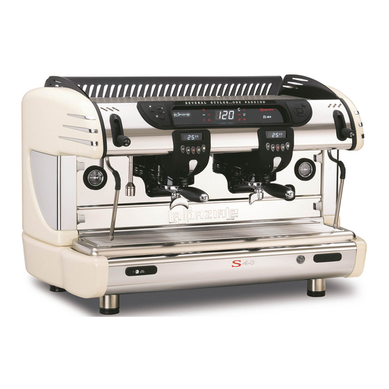
1. GENERAL DESCRIPTION OF THE MACHINE The S40 coffee machine is designed and manufactured by LA SPAZIALE S.p.A. to increase the profitability of the buffet bar service by reducing operating costs to the minimum. Fig. 1 LEGEND 7. -
Page 5: Control Panel Description
espresso coffee machines 1.1 CONTROL PANEL DESCRIPTION Fig. 2 LEGEND 2. Control panel warning light 1. Programming keyboard = Machine ON warning light = Temperature alarm warning = Programming keyboard = Boiler warning light light boiler temperature not BOILER = Value increase button reached = Technical assistance... -
Page 6: Coffee Dispensing Touchpad
espresso coffee machines 1.2 COFFEE DISPENSING TOUCHPAD SUPREMA CLASSIC Fig. 3 LEGEND 1. Display 2. 2 long coffees key 3. 2 short coffees key 4. Continuous delivery key 5. 1 long coffee key 6. 1 short coffee key LSI 024 - Rev. 01 - Ed. 10/2016... -
Page 7: General Warnings
espresso coffee machines 2. GENERAL WARNINGS Read carefully the instructions and warnings contained in this manual and in the “INSTRUCTION MANUAL FOR THE INSTALLER”, since they provide important indications concerning the installation of the appliance. Attention! This appliance may only be used for its intended purpose. Any other use is therefore considered as improper and unreasonable. - Page 8 espresso coffee machines Danger! If it becomes necessary to replace the machine’s power supply cable, utilise only these types: CET ELECTRIC H07RN-F 5 x 2.5mm (400V) for 2/3 group versions, 5 x 4mm (400V) for 4 group versions - CET ELECTRIC SINGLE PHASE 3 x 2.5mm (220V) 2 group versions, 3 x 4mm (220V) for 3/4 group versions.
- Page 9 espresso coffee machines Attention! The appliance must be installed on a flat bearing surface, the stability of which needs to be checked. Attention! The appliance must be installed where use and maintenance are restricted to trained staff. The electrical power system, water supply system and drainage system must prearranged by the customer in an ideal posi- tion to permit the correct installation.
-
Page 10: Removing The Packaging
espresso coffee machines 3. REMOVING THE PACKAGING After unpacking the machine, please check its integrity; in case of doubt, do not use it and consult the manufacturer. Packaging materials must not be left within children’s reach since they are potentially dangerous. Attention! The appliance weight is more than 30 kg and therefore, it cannot be moved by a single person alone. -
Page 11: Optional Accessories
espresso coffee machines 3.2 OPTIONAL ACCESSORIES (Supplied only on request of the customer) LEGEND I. Water softener L. Water line impurity filter M. Pressure reducer N. Detergent LSI 024 - Rev. 01 - Ed. 10/2016... -
Page 12: Installation
espresso coffee machines 4. INSTALLATION Place the machine on the support surface, lifting it up only from underneath. Adjust the feet so that the machine fits perfectly in a horizontal position and tilting slightly backwards. Before connecting the machine to the supply systems, ensure that the data on the nameplates correspond with the ratings where the machine is installed. - Page 13 espresso coffee machines Danger! The light blue conductor lead of cable (A) is connected to the neutral phase of the electrical system. Take note! 230 V single-phase connections are only possible with rating plate data refer a power less than 6300 W. LSI 024 - Rev.
-
Page 14: Water Mains Installation Diagram
espresso coffee machines 4.2 WATER MAINS INSTALLATION DIAGRAM Attention! The machine is supplied without water in the boiler to avoid exposure to temperatures less than 0°C that could cause irrepa- rable damage. Legend: 1 Water tap (previously installed by the customer). 2 Motor pump (provided with the machine - when not built in). -
Page 15: Drainage System
espresso coffee machines Danger! INSTALLATION OF THE WATER SOFTENER IS RECOMMENDED TO PROLONG THE LIFE OF THE MACHINE. Before installing the machine, check the hardness of the water and fit a softener based on the instructions of the manufacturer and to standards and regulations in force. Proceed to programme the automatic and/or volumetric softeners according to the manufacturer’s instructions. -
Page 16: Electrical Switch On Of The Appliance
espresso coffee machines 5. ELECTRICAL SWITCH ON OF THE APPLIANCE 1. Move the appliance switch under the bottom panel, to “I”. Fig. 6 Filling with water: After 3 seconds from switching on for the first time, the appliance will automatically fill the boiler with water. -
Page 17: Programming
espresso coffee machines For coffee preparation instructions, or for pouring hot water or dispensing steam for hot beverages, see the USE AND MAINTENANCE MANUAL. 6. PROGRAMMING The programming menu can be used to programme the boiler temperature, coffee doses, hot water pouring and the temperature of the M.A.T. system (optional). Press and hold down the “P”... -
Page 18: Programming Hot Water
espresso coffee machines 6.3 PROGRAMMING HOT WATER Press the “hot water delivery” key to commence delivery of the water. The main dis- play will show the pouring time. Once the required amount of water is in the jug, press the same key to stop the ongo- ing delivery and save it to memory. -
Page 19: Programming Access Block
espresso coffee machines 6.5 PROGRAMMING ACCESS BLOCK To quit programming, press and hold down the “cup warmer” for 5 seconds; in this mode it is possible to enable the PROGRAMMING ACCESS BLOCK function. With this function enabled, enter the programming mode with the “P” code then im- mediately press the “cupwarmer”... -
Page 20: Temperature Probe Calibration
espresso coffee machines 6.8 TEMPERATURE PROBE CALIBRATION Once inside the technical menu, the boiler temperature will automatically set to 120°C. It is possible to check the condition of the electrical heating element via the “°C” symbol; if it is fixed, the heating element is off and if it is flashing, it is operating and the machine is heating. -
Page 21: Washing The Boiler
espresso coffee machines 6.10 WASHING THE BOILER With the machine on, press and hold down the “hot water delivery” key for 3 seconds. The machine dispenses water from the wand for about 2 minutes, then restore the correct water level in the boiler. 6.11 GROUP WASHING With the machine on, press and hold down any one of the pouring keys for 15 sec;... -
Page 22: Technical Assistance Program - G.a. - (Optional)
espresso coffee machines 7 TECHNICAL ASSISTANCE PROGRAM – G.A. - (optional) The scheduled technical assistance program makes it possible to keep some appliance parameters under control, making it possible to set a minimum threshold after which an alarm signal is given. The program makes it possible to organise regular routine maintenance for the delivery groups (enabling the SERVICE menu) and/or the replacement of the filter cartridge or resin regeneration for the softener (enabling the FILTER menu). - Page 23 espresso coffee machines To indicate that the technical assistance is deactivated. To enable one or both available controls, proceed as follows: hold down the button for about 3 seconds, this opens the SERVICE menu and the display will read: Fig. 16 Where “Y”...
- Page 24 espresso coffee machines Take note! The set number is not a count of the number of cups of coffee delivered by the appliance, it is just a control over the solenoid valve insertion cycles for the groups and therefore, for example, 100 solenoid valve cycles do not correspond to 100 delivered cups of coffee.
- Page 25 espresso coffee machines After confirming the setting, the program passes onto the settings for the softener FILTER menu. The display will show: Fig. 19 Where “Y” (Yes) will be flashing. To select “N” (No) press one of the 2 arrow keys , “N”...
- Page 26 espresso coffee machines Where the first “0” on the right is flashing. Pressing the button will increase the number (0 - 9), while pressing the button moves to the most important digit on the left (the selected digit will flash to show that it can be changed). Once the litres value has been set, confirm the setting by pressing the button , and it is possible to quit the programming function.
- Page 27 espresso coffee machines Take note! The visualization is alternatively shown on the display only if both controls have been enabled, otherwise, only the enabled control is displayed. The number of cycles is decreased after every 50 solenoid valve activations. The number of litres for the filter is reduced after every 10 litres of water con- sumed.
- Page 28 espresso coffee machines Where “1750 ml” is the correspondence between 1 minute of operation of the automatic boiler refill system and the amount of water increases/decreases the setting (1000 ml – 2000 ml). introduced, given in millilitres. Pressing the buttons Pressing the button confirms the setting and returns to the initial display menu.
-
Page 29: Series S40 Alarms Manager
espresso coffee machines 7.1 SERIES S40 ALARMS MANAGER This series of symbols informs of any machine operation anomalies. In case of machine lock alarm, the main display and the delivery group displays show the only central lines switched on. SYMBOL ALARM TYPE PROBLEM POSSIBLE SOLUTION... - Page 30 espresso coffee machines SYMBOL ALARM TYPE PROBLEM POSSIBLE SOLUTION M.A.T. system temperature M.A.T. temperature probe short Check the machine’s M.A.T. probe failure. circuit or interrupted. system. Take note! When this alarm is triggered, it is in any case possible to automatically emulsify the milk by holding down the M.A.T.
-
Page 31: Notes For The Service Engineer
espresso coffee machines 7.2 NOTES FOR THE SERVICE ENGINEER SETTING THE ELECTRONIC CONTROL BOARD The electronic control board can be set to manage two different water level controls (probe or float) and to control the two different group delivery versions: automatic (Suprema) or semiautomatic (Classic). The electronic control board is equipped with a selector to configure the board. -
Page 32: Electronic Expansion Board
espresso coffee machines 7.3 ELECTRONIC EXPANSION BOARD When replacing the electronic expansion boars, always make sure that the MC1 contact is open before switching on the machine. With the machine in standard configuration, the dip 2 of KD1 must be set to OFF. When the machine is suitable to operate with the M.A.T. -
Page 33: Check/Calibration Of Pump Motor Pressure
espresso coffee machines 7.3.1 Check/Calibration of pump motor pressure Below are the operations to be performed when checking and/or calibrating the pres- sure of the pump motor inside the machine. 1. Remove the drip tray and grating. Fig. 27 2. Remove the 2 bottom protective caps and the 2 Allen screws that fasten the bot- tom drain cover and then remove the drain cover and remove it. -
Page 34: Checking/Calibrating The Opening Pressure For The Expansion Valve
espresso coffee machines 7.3.2 Checking/Calibrating the opening pressure for the expansion valve The following section lists the checks/calibration operations needed for the expan- sion valve. With the machine on and at the right temperature, press the delivery buttons of all groups and after about 5 seconds, connect a portafilter with incorporated pressure gauge to one of the groups and switch off the delivery of the other groups. - Page 35 espresso coffee machines 2. Remove the 2 bottom protective caps and the 2 Allen screws that fasten the bot- tom drain cover and then remove the drain cover and remove it. Fig. 31 3. Remove the plate covering the system by loosening the two fastening screws. Fig.
-
Page 36: Disassembly Of The Machine
espresso coffee machines 8 DISASSEMBLY OF THE MACHINE 8.1 DISASSEMBLY OF THE SIDE PANELS 1. Remove the glass side panels by lifting them as shown in the figure. Fig. 34 2. Using a screwdriver, slacken the upper fixing screws of the side panels as shown in the figure. - Page 37 espresso coffee machines 4. Pull the side panel away from the machine and remove it as shown in the figure. Fig. 37 5. Proceed in the same way for the other side panel. 6. Reposition the elements previously removed in reverse order. LSI 024 - Rev.
-
Page 38: Disassembly Of The Upper Front Panel
espresso coffee machines 8.2 DISASSEMBLY OF THE UPPER FRONT PANEL 1. Remove the side glass panels by lifting them as shown in the figure. Fig. 38 2. Unscrew and remove the steam dispensation control lever knobs as shown in the figure. - Page 39 espresso coffee machines 3. Using a screwdriver, slacken the lower fixing screw of the front panel as shown in the figure. Fig. 41 4. Slide the front panel forwards until it stops. Fig. 42 5. Rotate the front panel as shown in the figure. 6.
-
Page 40: Disassembly Of The Control Panel
espresso coffee machines 8.2.1 Disassembly of the control panel 1. Proceed to disassemble the upper front panel as previously described 2. Using a screwdriver slacken the fixing screws of the control panel as shown in the figure and disconnect the cables between the panel and the front CPU. Fig. -
Page 41: Disassembly Of The Drainage Cover Panel
espresso coffee machines 8.3 DISASSEMBLY OF THE DRAINAGE COVER PANEL 1. Remove the water collection basin and the relative grill. Fig. 47 2. Remove the 2 lower protection caps and the 2 Allen screws relative to the fixing of the lower drainage cover panel and remove it. Fig. -
Page 42: Disassembly Of The Coffee Dispensing Group
espresso coffee machines 8.3.1 Disassembly of the coffee dispensing group 1. Remove the filter holders from the machine. Fig. 50 2. Using a screwdriver, rotate the two screws a quarter of a turn that are positioned to the side of the coffee dispensing group cover. Fig. - Page 43 espresso coffee machines 4. Using a screwdriver, remove the 4 screws at the side of the coffee dispensing group. Fig. 53 5. Disconnect the cables and pull the coffee dispensing group downwards. Fig. 54 6. Reposition the elements previously removed in reverse order. LSI 024 - Rev.
-
Page 44: Disassembly Of The Upper Cover
espresso coffee machines 8.4 DISASSEMBLY OF THE UPPER COVER 1. Remove the glass side panels by lifting them as shown in the figure. Fig. 65 2. Remove the grills of the cup warmer plate by lifting them as shown in the figure. Fig. - Page 45 espresso coffee machines 4. Remove the front plate of the cup warmer plate as shown in the figure. Fig. 68 5. Using the rear part as the fulcrum, pull up the rear plates of the cup warmer plate and remove them as shown in the figure. Fig.
- Page 46 espresso coffee machines 7. Remove the upper cover as shown in the figure. Fig. 71 8. Reposition the elements previously removed in reverse order. LSI 024 - Rev. 01 - Ed. 10/2016...
- Page 47 espresso coffee machines DIAGRAMS LSI 024 - Rev. 01 - Ed. 10/2016...
-
Page 48: Diagrams For Electronic Board Connections
espresso coffee machines 9. DIAGRAMS FOR ELECTRONIC BOARD CONNECTIONS 9.1 EXPANSION BOARD Key: SMAT M.A.T. system temperature probe COUNTER Display connection for 1st EV AIR MAT connection for AIR M.A.T. (optional). group from the right. solenoid valve (optional). EV MAT SER2 M.A.T. -
Page 49: Classic/ Suprema Cpu
espresso coffee machines 9.2 CLASSIC/ SUPREMA CPU LSI 024 - Rev. 01 - Ed. 10/2016... - Page 50 espresso coffee machines Key: Connection for pump motor. Volumetric counter for 3rd group from the right. Connection for static relay. Volumetric counter for 4th group from the right. PHASE NEUTRAL 10 V Transformer outlet connection. Connection for programming button pad. K1 K2 Connection for static relays.
-
Page 51: Front Led Display
espresso coffee machines 9.3 FRONT LED DISPLAY Key: Connection for LED and program- SER1 Connection for Classic/Suprema ming button pad for the control CPU. panel. LSI 024 - Rev. 01 - Ed. 10/2016... -
Page 52: Group Led Display
espresso coffee machines 9.4 GROUP LED DISPLAY Key: COUNTER IN Expansion control board COUNTER OUT Group display connection. connection. LSI 024 - Rev. 01 - Ed. 10/2016... -
Page 53: Wiring Diagram
espresso coffee machines 9.5 WIRING DIAGRAM LSI 024 - Rev. 01 - Ed. 10/2016... - Page 54 espresso coffee machines Key: Motor pump. Motor pump control board relay. Cup warmer heating element. Solenoid valve control board relay for 1st group from the Boiler heating element. right. EVAL Automatic water filling solenoid valve. Solenoid valve control board relay for 2nd group from the Solenoid valve for 1st group from the right.
-
Page 55: Hydraulic Diagram
espresso coffee machines 9.6 HYDRAULIC DIAGRAM LSI 024 - Rev. 01 - Ed. 10/2016... - Page 56 espresso coffee machines Key: Water cock (put in place by end customer). Heat exchanger 4th group from the right. Pressure reducer (optional). Coffee delivery solenoid for 1st group from the right. Softener (optional). Coffee delivery solenoid for 2nd group from the right. Impurity filter (optional).
- Page 57 All LA SPAZIALE espresso machines are made with a heat exchanger system between the boiler and the coffee delivery group. A special patented system, the only one in the world, for heat adjustment of the delivery group, based on the circulation of steam instead of water.
-
Page 58: Technical Data
espresso coffee machines 10 TECHNICAL DATA Fig. 72 DIMENSIONS AND WEIGHT POWER SUPPLY RATING AND ABSORPTION 2 GR 3 GR 4 GR 2 GR 3 GR 4 GR 1080 1320 VOLT 220/240/400 220/240/400 220/240/400 50/60 50/60 50/60 3800 5100 6300 WEIGHT KG LSI 024 - Rev. - Page 59 espresso coffee machines LSI 024 - Rev. 01 - Ed. 10/2016...
- Page 60 espresso coffee machines LSI 024 - Rev. 01 - Ed. 10/2016...
- Page 62 La Spaziale S.p.A. Via E. Duse, 8 40033 Casalecchio di Reno Bologna - (Italy) ¥ +39 051 611.10.11 +39 051 611.10.11 +39 051 611.10.40 info@laspaziale.com...
Need help?
Do you have a question about the S40 Classic and is the answer not in the manual?
Questions and answers