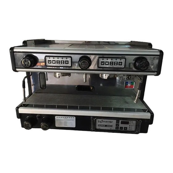
Table of Contents
Advertisement
Advertisement
Table of Contents

Summarization of Contents
Conformity Declarations
2004/108/CE EMC Directive Compliance
Details compliance with the Electromagnetic Compatibility Directive, listing harmonized standards.
2006/95/CE Low Voltage Directive Compliance
Details compliance with the Low Voltage Directive, listing harmonized standards.
97/23/EC Pressurised Equipment Directive (PED) Compliance
Declares conformity with the PED, specifying essential requirements and assessment procedures.
Chapter 1 General Notes
1.1 Rating Plates
Details about the appliance's rating plate, including location and access.
1.2 General Warnings
Important safety warnings and general precautions for installation and use.
1.3 Machine Equipment
Lists the components and accessories included with the appliance.
1.4 Warnings for the Installer
Specific warnings and instructions for installation personnel.
1.5 Installation
Procedures for correctly placing and leveling the appliance during installation.
1.6 Electric Installation Diagram
Illustrates the electrical connections for heating elements and power cables.
1.7 Water Mains Installation Diagram
Shows the diagram for connecting the appliance to the water supply.
1.8 Drain System
Instructions for connecting the appliance's drain pipe to the drainage system.
1.9 Gas System Installation Diagram (Optional)
Diagram for optional gas system connections and related tables.
1.10 Starting Up and Adjusting the Appliance
Steps for initial startup and adjusting the motor pump pressure.
1.11 Setting Switch On and Operating Temperature (Gas System)
Procedures for adjusting gas system settings and operating temperature.
Chapter 2 SUPER 3000 Range
2.1 Ultra Model
Details on the Ultra model, including operating temperature adjustment for electric systems.
2.2 Elettrik Model
Overview of the Elettrik model's control panel and functions.
2.3 Seletron Model
Description of the Seletron model's control panel and features.
2.4 Alarms Control - Elettrik – Seletron Models
Explanation of alarm messages and their meanings for Elettrik and Seletron models.
2.5 Diagrams for Electronic Board Connections
Wiring diagrams showing connections for Ultra, Elettrik, and Seletron models.
2.6 Wiring Diagrams
Detailed wiring diagrams for the Ultra model.
2.7 Parts
Illustrations and labels for the components of ULTRA, ELETTRIK, and SELETRON models.
Chapter 3 NEW - RAPID – SPAZIO - SPECIAL Range
3.1 Model 3000 - EC (except Spazio) - EP
Information on Model 3000 EC/EP, including temperature adjustment.
3.2 EK Model
Details on the EK model, including temperature adjustment and dose setting.
3.3 Alarm Control – EK Model
Explains alarm indicators and troubleshooting for the EK model.
3.4 Wiring Diagrams
Wiring diagrams for the NEW EC - 3000 model.
3.5 Components
Illustrations and labels for the components of RAPID, SPAZIO, and NEW models.
3.6 Components (SPECIAL)
Illustrations and labels for SPECIAL models (1 Group, 2 Groups Spazio, 2 Groups).
Chapter 4 S3 Range
4.1 EP Model
Information on the S3 EP model, including temperature adjustment and infusion pouring.
4.2 EK Model
Details on the S3 EK model, including temperature adjustment and dose setting.
4.3 Alarm Control – EK Model
Explains alarm messages and troubleshooting for the S3 EK model.
4.4 Seletron Model
Overview of the S3 Seletron model's control panel and basic settings.
4.5 Alarm Control – Seletron Model
Explains alarm messages and troubleshooting for the S3 Seletron model.
4.6 Diagrams for Electronic Board Connections
Shows electronic board connection diagrams for the S3 EK model.
4.7 Wiring Diagrams
Wiring diagrams for the S3 EP model.
4.8 Components
Illustrations and labels for S3 EP and S3 EK models.
Chapter 5 S5 Range
5.1 EP Model
Information on the S5 EP model, including control board settings and temperature adjustment.
5.2 Alarm Manager – EP Model
Explains alarm conditions and troubleshooting for the S5 EP model.
5.3 EK Model
Details on the S5 EK model, including temperature adjustment and dose setting.
5.4 Alarm Control - EK Model
Explains alarm indicators and troubleshooting for the S5 EK model.
5.5 Automatic Milk Foaming System With Adjustable Temperature - M.A.T. - (optional)
Guide to setting temperature and air suction for automatic milk foaming.
5.6 Milk Sensor Calibration (optional)
Instructions for calibrating the milk sensor to ensure accurate temperature readings.
5.7 Delivery Group Individual Temperature Control - I.T.C. - (optional)
How to adjust brewing temperature for each delivery group independently.
5.8 Scheduled Technical Assistance Program - G.A. - (optional)
Information on setting up maintenance schedules and alarms.
5.9 Diagrams for Electronic Board Connections
Shows electronic board connection diagrams for the S5 models.
5.10 Wiring Diagrams
Wiring diagrams for the S5 EP model.
5.11 Parts
Illustrations and labels for the components of S5 EP and S5 EK models.
Chapter 6 COMPACT RANGE and S5 1 GROUP
6.1 EP Model
Information on the COMPACT EP model, including temperature adjustment and cup warmer.
6.2 Alarm Control – EP Model
Explains alarm conditions for the COMPACT EP model.
6.3 EK Model
Details on the COMPACT EK model, including temperature adjustment and cup warmer.
6.4 Alarm Manager – EK Model
Explains alarm indicators for the COMPACT EK model.
6.5 Diagrams for Electronic Board Connections
Shows electronic board connection diagrams for Compact EP/EK.
6.6 Wiring Diagrams
Wiring diagrams for COMPACT and S5 1 Group EP models.
6.7 Parts
Illustrations and labels for COMPACT EP and EK models.


Need help?
Do you have a question about the SUPER 3000 and is the answer not in the manual?
Questions and answers