Table of Contents
Advertisement
Quick Links
Advertisement
Table of Contents

Related Manuals for AEMC OX7102-CII


Summary of Contents for AEMC OX7102-CII
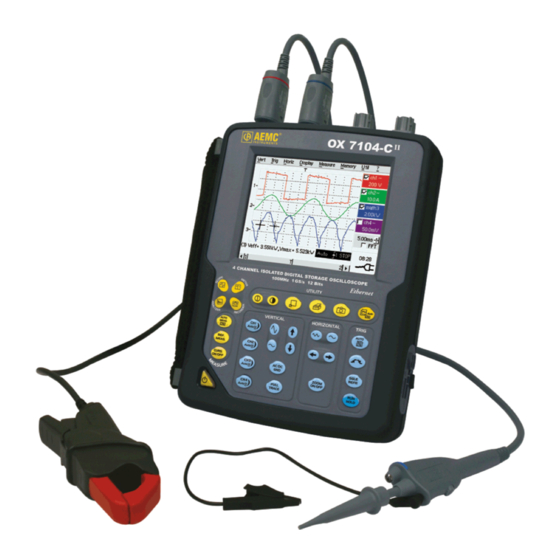
- Page 1 Portable Oscilloscopes 100MHz 2-channel OX 7102-C 100MHz 4-channel OX 7104-C User Manual ® ® AEMC Instruments d.b.a. Chauvin Arnoux , Inc. 15 Faraday Drive • Dover, NH 03820 Tel. (603) 749-6434 • Fax: (603) 742-2346 99-MAN 100341 – v1 – 09/09...
-
Page 2: Table Of Contents
General Instructions Contents General instructions Chapter I General....................4 Software updating................. 6 Description of the instrument Chapter II Presentation ..................7 Views ...................... 8 Terminal Boards.................. 12 Activation..................... 14 Battery....................15 Using the menus ................. 17 Network....................17 Description of Accessories Chapter III HX0061 .................... - Page 3 General Instructions Harmonic Analysis Mode Chapter VI Display ....................109 Menus "Vertical" menu....... 113 "Horizontal" menu....... 115 "Display" menu....... 116 "Measure" menu....... 116 "Memory" menu....... 117 "Utilities" menu....... 117 "Help" menu....... 117 Recorder Mode Chapter VII Keys....................119 Display ....................122 Menus "Vertical"...
-
Page 4: General Instructions
General Instructions General Instructions You have just purchased a portable digital oscilloscope. Introduction Congratulations on your choice and thank you for your trust in the quality of our products. Here is the family of instruments to which it belongs: color 2-channel 100 MHz 1 GS/s sample... -
Page 5: General
General Instructions General instructions (cont'd) Definition of CAT I: CAT I circuits are circuits protected by low level transient over-voltage measurement limiters categories Example: protected electronic circuits CAT II: CAT II circuits are household or similar appliance power circuits, which may carry medium-level transient over-voltage. - Page 6 • Allow to dry before any further use. Update the instrument's internal software • Log on to the www.aemc.com website. • From the Home page, select “Software and Firmware Updates”. • Select and download the Firmware corresponding to your instrument model.
-
Page 7: Description Of The Instrument
Description of the instrument Description of the instrument This manual describes the operation of an OX 7104-C oscilloscope. OX 7104-C : - adjustment of the 4 channels is accessible by the opposite keys. OX 7102-C - adjustment of the 2 channels is accessible by the opposite keys. This instrument is part of our range of portable oscilloscopes. - Page 8 Description of the instrument Description of the instrument (cont'd) OX 7102 Front Panel Rear Panel II - 8 SCOPIX Oscilloscopes...
- Page 9 Description of the instrument Description of the instrument (cont'd) OX 7104 Front Panel Rear Panel Stylus Strap Fans Stand Cover of the battery pack Using the stand The oscilloscope is equipped with a stand, which makes it possible to give it an angle, when used as a benchtop oscilloscope.
-
Page 10: Views
Description of the instrument Description of the instrument (cont'd) Markings on rear panel TO AVOID ELECTRICAL SHOCK DISCONNECT LEADS, PROBES AND POWER SUPPLY BEFORE REMOVING COVER ONLY REPLACE WITH 9.6V NiMH CUSTOM PACK Side view Marking RS-232/ ETHERNET Eternal connector power supply connector... - Page 11 Description of the instrument Description of the instrument (cont'd) Measurement terminal block OX 7102 Marking OX 7104 Marking SCOPIX Oscilloscopes II - 11...
- Page 12 Description of the instrument Description of the instrument (cont'd) The main functions of the instrument are accessible on the front panel and can Front (description) be modified using the touch-sensitive pad (with its stylus) or the menu bar. • 1 On/Standby/Off key power on by a short press •...
- Page 13 Description of the instrument SCOPIX Oscilloscopes II - 13...
-
Page 14: Battery
Description of the instrument Description of the instrument (cont'd) Initial operation of The portable oscilloscopes in this range are designed to operate on a power source delivering 98 to 264 V (ACrms) or in stand-alone mode with a the oscilloscope battery. - Page 15 Description of the instrument Description of the instrument (cont'd) Installation of the To prevent any electric shocks, remove the Probix adapters and the battery in the external power supply lead before installing or replacing the battery. oscilloscope • Using a coin or a screwdriver, turn by a quarter turn (counter-clockwise) the 2 plastic screws located on the cover of the battery compartment located at the rear of the instrument •...
- Page 16 Description of the instrument Description of the instrument (cont'd) Charging the battery Once the battery is located in its compartment, follow the external power supply start-up instructions. • To speed up recharging of the battery, switch off the power to the oscilloscope by a long press on the ON/OFF button.
-
Page 17: Using The Menus
Description of the instrument Description of the instrument (cont'd) The various instrument parameters can be accessed via menus. Using the menus The rules for using, selecting and modifying an option are identical to those defined by Microsoft Windows. To input a numerical value (time base, alignment, etc.), a double click on the numerical field brings up a virtual keyboard: The window title indicates the adjustment in process and the measurement unit... - Page 18 Description of the instrument Description of the instrument (cont'd) Network (cont’d) IP addresses An IP address is coded over 4 bytes, displayed in decimal format. Example: 132.147.250.10). Each field may be coded between 0 and 255 and is separated by a decimal point. Unlike the physical address, the IP address can be modified by the user.
- Page 19 Description of the instrument Description of the instrument (cont'd) SUBNET mask If the result of the operation ' AND LOGICAL' between IP address of the and GATEWAY recipient of the message and the value of subnet mask is different from the address of the recipient of the message, this message is sent to the gateway which will be given the responsibility to forward it to destination.
- Page 20 Description of the instrument II - 20 SCOPIX Oscilloscopes...
- Page 21 Description of Accessories SCOPIX Oscilloscopes III - 21...
-
Page 22: Description Of Accessories
Description of Accessories Description of Accessories Concept The portable oscilloscopes in this range use Probix intelligent probes and adapters, offering users active safety. When connected to an oscilloscope input, a safety message in English concerning the probe or adapter used indicates: •... -
Page 23: Probix
Description of Accessories Description of Accessories (cont’d) HX0030 (Cat. #2127.73) Probix 1/10 probe The HX0030 accessory is a 1/10 probe equipped with a LED and pushbuttons (A and B), the action of which can be programmed via the menu: "Green" "chX"... -
Page 24: Hx0031
Description of Accessories Description of Accessories (cont’d) HX0031 (Cat. #2124.74) Probix BNC adapter The HX0031 accessory is a BNC adapter, connected via a BNC lead to a measuring signal. This adapter is a PLUG and PLAY element. Its internal electronics are powered by the oscilloscope. -
Page 25: Hx0032
Description of Accessories Description of Accessories (cont’d) HX0032 (Cat. #2124.75) Probix BNC 50Ω The HX0032 accessory is an adapter with a 50 Ω load, connected via a BNC adapter lead to a measuring signal. This adapter is a PLUG and PLAY element. Its internal electronics are powered by the oscilloscope. -
Page 26: Hx0033
Description of Accessories Description of Accessories (cont’d) HX0033 (Cat. #2124.76) Probix banana The HX0033 accessory is an adapter used to connect leads with banana adapter plugs. ∅ 4 mm: This adapter is a PLUG and PLAY element. Its internal electronics are powered by the oscilloscope. -
Page 27: Hx0034
Description of Accessories Description of Accessories (cont’d) HX0034 (Cat. #2124.77) Probix current The HX0034 accessory is a current clamp using a Hall-effect cell to clamp adapter measure DC or AC currents up to 80 A peak, without any intervention on the electrical installation (cutting off the current to be measured). -
Page 28: Hx0035
Description of Accessories Description of Accessories (cont’d) HX0035 (Cat. #2124.78) The HX0035 accessory is an adapter used to linearize temperature Probix K Thermocouple measurements from a K-type thermocouple. adapter This adapter is a PLUG and PLAY element. Its internal electronics are powered by the oscilloscope. - Page 29 Description of Accessories Measurements are available 30 sec. after connection of the HX0035, after a calibration phase. During this phase, the following message is displayed: SCOPIX Oscilloscopes III - 29...
-
Page 30: Hx0072
Description of Accessories Description of Accessories (cont’d) HX0072 (Cat. #2124.91) ® Probix HX0072 is an AmpFlex Probix probe, to be used to measure AC currents of AmpFLEX probe up to 3000 A This adapter is a PLUG and PLAY element. Its internal electronics are powered by the oscilloscope. -
Page 31: Hx0073
Description of Accessories Description of Accessories (cont’d) HX0073 (Cat. #2124.92) Probix HX0073 is an MiniFlex™ Probix probe, to be used to measure AC currents MiniFlex™ of up to 300 A probe This adapter is a PLUG and PLAY element. Its internal electronics are powered by the oscilloscope. - Page 32 Description of Accessories Description of Accessories (cont’d) Connection Disconnection A window indicating the safety conditions is displayed when you connect or disconnect a Probix to/from one of the instrument channels: General characteristics of the last adapter connected Input: Maximum voltage of the signal measured by the Probix adapter...
-
Page 33: Recommandations For Use
Description of Accessories Description of Accessories ((cont’d) Recommandations for use Connection of 1. To prevent electric shocks or possible fire, never use the earthing spring of reference the 1/10 probe for voltages > 30 Vrms in relation to the earth. conductors for the 1/10 Probix HX0030 probe... - Page 34 Description of Accessories III - 34 SCOPIX Oscilloscopes...
-
Page 35: Oscilloscope Mode
Oscilloscope Mode - The Keys Oscilloscope Mode The Keys By pressing this key, you can select the "oscilloscope" mode. 5 "UTILITY" keys or key pad Direct access to LCD contrast adjustment. When this key is pressed, the display mode switches from normal to "full screen"... - Page 36 Oscilloscope Mode - The Keys Oscilloscope Mode (cont’d) 4 "Trigger" keys Sets the trigger level to the average value of the signal (50%) without modifying the trigger coupling. When pressed in combination with a CHx key, this activates the same function, after first selecting the corresponding channel as the trigger source.
- Page 37 Oscilloscope Mode - The Keys Oscilloscope Mode (cont'd) 3 "MEASURE" keys Activates or deactivates the display of the window for the 19 automatic measurements on the reference trace. When pressed in combination with a CHx key, it displays the measurements concerning the corresponding channel. By means of successive presses, this selects one of the displayed traces as the reference trace for the automatic and manual measurements.
- Page 38 Oscilloscope Mode - The Keys Oscilloscope Mode (cont'd) Validated channel: Display enabled, trace displayed after RUN Definition of terms used Displayed channel: Channel validated, trace present on the screen Selected channel: The parameters of this channel can be set with the keys: 5 "VERTICAL"...
- Page 39 Oscilloscope Mode - The Keys Oscilloscope Mode (cont'd) Activates or deactivates horizontal splitting of the display zone. When activated, the "Full Trace" function is indicated by: - the presence of a continuous horizontal line in the middle of the display area.
- Page 40 Oscilloscope Mode - Display Oscilloscope Mode (cont'd) Display Display Cursor2 Composition The oscilloscope display is divided into 4 functional zones. Direct access to main settings 4. Menu bar 3. Display area 1. Status area Display and adjustment of current value IV - 40 SCOPIX Oscilloscopes...
- Page 41 Oscilloscope Mode - Display Oscilloscope Mode (cont'd) 1. Status area Three types of general information appear in this area: • The bargraph representing the screen position, the trigger and the cursors in the acquisition memory. • The instrument permanent settings. •...
-
Page 42: Keys
Oscilloscope Mode - Display Oscilloscope Mode (cont'd) 2. Control area The parameters displayed in this area are: • The parameters of each channel and trace: display, sensitivity, coupling, bandwidth limitation, vertical scale, function, Zoom. • The time base value, the presence of a Zoom and a change in the signal representation domain (FFT). - Page 43 Oscilloscope Mode - Display Oscilloscope Mode (cont'd) The grouped "Source" and "Trigger Mode" menus can be opened by a double press with the stylus on the time base area. RUN/STOP starts and stops acquisition from this menu. The acquisition status is indicated in the status area on the screen. The symbol "...
- Page 44 Oscilloscope Mode - Display Oscilloscope Mode (cont'd) Display elements > ϕ Definition of display Refs. Elements selectable using the touch-sensitive pad Trace displayed Trace displayed Vertical position indicator of the reference level of the trace displayed and identification of the trace number Indication of Trigger time position Division of graticule Position indicator of the cursors for the first automatic...
- Page 45 Oscilloscope Mode - Display Oscilloscope Mode (cont'd) Menu accessible By double-tapping with the stylus in the from display area display area, the menu concerning the display can be opened directly. The "Full Screen" and "Zoom Out" options are directly accessible (see §. Display Menu).
- Page 46 Oscilloscope Mode - Display Oscilloscope Mode (cont'd) Calibration of the Follow the instructions on the screen. touch-sensitive screen (cont'd) Corner of the touch screen Use the stylus to point at the center of the 4 patterns displayed on the screen. Validation of the input is indicated by modification of the pattern.
- Page 47 Oscilloscope Mode - The "Vertical" Menu Oscilloscope Mode (cont'd) The "Vert" Menu (∗) (∗) (∗) (∗) ≠ Advanced mode Advanced mode SCOPIX Oscilloscopes IV - 47...
- Page 48 Oscilloscope Mode - The "Vertical" Menu Oscilloscope Mode (cont'd) Opens the "Trace display" menu for validating or devalidating the traces. Display Validation of the selections by "OK". Exit from the menu without modification by "Cancel". The " " symbol in front of a trace indicates that it has been validated. The traces can be validated or devalidated from the control area by using the stylus.
-
Page 49: Display
Oscilloscope Mode - The "Vertical" Menu Oscilloscope Mode (cont'd) Measurement unit Modification of the selected channel's vertical scale unit. The modification is performed by means of the stylus, using the table of usable characters after selecting the “measure unit” zone. key deletes the character preceding the cursor in this area. - Page 50 Oscilloscope Mode - The "Vertical" Menu Oscilloscope Mode (cont'd) math1 math2 For each trace, definition of a mathematical function and the vertical scale. math3 math4 If "Advanced" mode is not activated, simple functions (Inversion, Addition, Subtraction, Multiplication and Division of curves) can be selected and linked to the curves 1 or 2.
- Page 51 Oscilloscope Mode - The "Vertical" Menu Oscilloscope Mode (cont'd) Examples • Predefined divv() function used on its own: math3 = divv(3). Use of predefined mathematical functions The trace is equal to 3 vertical divisions. • Predefined step() function associated with a trace: - math2 = ch1*step(t-divh(4)) The result of math2 is 0 vertical divisions as long as t is less than four horizontal divisions (t-divh(4) <...
- Page 52 Oscilloscope Mode - The "Vertical" Menu Oscilloscope Mode (cont'd) Example 1 Addition of two traces Vhigh Vpp(ch1) = Vpp(ch2) = 6 V Sensitivity (ch1) = 1 V/div Sensitivity (ch2) = 1 V/div Traces ch1 and ch2 are optimised on 6 vertical divisions. Vamp ch1 = 6 vertical divisions Vamp ch2 = 6 vertical divisions - math3 = ch1+ch2...
- Page 53 Oscilloscope Mode - The "Vertical" Menu Oscilloscope Mode (cont'd) Example 2 Multiplication of two traces Sensitivity(ch1) = 5 V/div Sensitivity(ch2) = 5 V/div Vamp(ch1) = Vamp(ch2) = 10 V Vamp ch1 = 2 vertical divisions Vamp ch2 = 2 vertical divisions - math3 = ch1*ch2 As for the addition of traces, there is a even more significant high and low overshoot.
- Page 54 Oscilloscope Mode - The "Vertical" Menu Oscilloscope Mode (cont'd) You can then open the menu “Vertical Scale" of math3 (see §. Opening from math3, math4) to assign a coefficient to the result and to modify the measuring unit. In our example: •...
- Page 55 Oscilloscope Mode - The "Vertical" Menu Oscilloscope Mode (cont'd) Example 3 - math3 = divv(3)*sin (2*pi*t/500) (∗) Association of predefined functions The trace obtained is a sine-curve produced using the predefined function "sin()". The amplitude is 6 divisions. The period equal to 500 samples (∗∗) (2 horizontal divisions) depends on the time base.
- Page 56 Oscilloscope Mode - The "Vertical" Menu Oscilloscope Mode (cont'd) Production of an math1 = sin (pi*t/divh(1))*exp(-t/divh(6))*divv(4) attenuated sine wave using predefined functions "sin (pi*t/divh(1))" can be used to modify the number of periods. "exp (-t/divh(6))" can be used to modify the level of attenuation. IV - 56 SCOPIX Oscilloscopes...
- Page 57 Oscilloscope Mode - The "Vertical" Menu Oscilloscope Mode (cont'd) Function definition (cont'd) Files Contains the list of the functions (.FCT) saved by the user, along with two predefined files. By selecting the name of the function with the stylus (function name in blue), you can transfer the definition of the function into the 2 lines provided for that purpose.
- Page 58 Oscilloscope Mode - The "Vertical" Menu Oscilloscope Mode (cont'd) Save Saves the definition of the function using the “File Copy “ menu (see §. Memory Menu). The file is assigned the suffix .FCT and appears in the list of saved files. Completely resets the function definition.
-
Page 59: Trigger" Menu
Oscilloscope Mode - The "Trigger" Menu Oscilloscope Mode (cont'd) The "Trig" Menu SCOPIX Oscilloscopes IV - 59... - Page 60 Oscilloscope Mode - The "Trigger" Menu Oscilloscope Mode (cont'd) This range of portable oscilloscopes is equipped with "advanced triggers". Definition • The "Main" tab can be used to choose and parameterize the main trigger source. • The "Delay" and "Count" trigger modes require parameterization of a second "auxiliary"...
- Page 61 Oscilloscope Mode - The "Trigger" Menu Oscilloscope Mode (cont'd) Selection of the "Trigger Parameters". Parameters Trigger on edge Main Source Selects a channel as a trigger source. Coupling Selection of the filter for the main trigger source: AC coupling (10 Hz to 200 MHz): blocks the DC component of the signal DC coupling (0 to 200 MHz): allows the entire signal through...
- Page 62 Oscilloscope Mode - The "Trigger" Menu Oscilloscope Mode (cont'd) Example Signal injected on CH1: a train of three 6 V pulses at a frequency of 20 kHz with a 500 mV component, separated by 500 µs. The trigger is regulated with channel 1 as a source, level at 2.04 V, on a rising edge.
- Page 63 Oscilloscope Mode - The "Trigger" Menu Oscilloscope Mode (cont'd) Selection of pulse-width trigger. In all cases, the effective trigger occurs on the Pulse pulse trailing edge. < triggers on a pulse if its duration is less than the value set triggers on a pulse if its duration is equal to the value set >...
- Page 64 Oscilloscope Mode - The "Trigger" Menu Oscilloscope Mode (cont'd) Delay Selection of edge trigger with delay The delay is triggered by the auxiliary source. Effective triggering occurs after the end of the delay on the next event from the main source. Trigger delay 35.2µs Adjustment with the stylus using the setting scroll bar to choose the...
- Page 65 Oscilloscope Mode - The "Trigger" Menu Oscilloscope Mode (cont'd) Example Signal injected on CH1: a train of three 6 V pulses at a frequency of 20 kHz separated by 500 µs. The trigger is active after the end of the delay (35.2 µs) on the first ascending edge.
- Page 66 Oscilloscope Mode - The "Trigger" Menu Oscilloscope Mode (cont'd) Selects the edge trigger with counting of events. Count The count is triggered by the auxiliary source. The main source serves as a clock for the count. Effective triggering occurs after the end of the count on the next event from the main source.
- Page 67 Oscilloscope Mode - The "Trigger" Menu Oscilloscope Mode (cont'd) Example Signal injected on CH1: a train of five 6 V pulses at a frequency of 20 kHz separated by 500 µs. The trigger is set on the descending edge. The first edge activates the trigger. It is not included in the count. The trigger is triggered on the third descending edge of the pulse train.
- Page 68 Oscilloscope Mode - The "Trigger" Menu Oscilloscope Mode (cont'd) Trigger on a TV signal See Chapter VI - Applications: §. Video signal display. This menu is only applicable to the CH1 input. Standard Trigger on a specific line number. The trigger starts on the front edge of the line synchronization signal.
-
Page 69: Menus
Oscilloscope Mode - The "Trigger" Menu Oscilloscope Mode (cont'd) Acquisitions and refreshment of the screen at each trigger event. Triggered mode Acquisition and automatic refreshing of screen even when there is no trigger Automatic mode event. Visible traces, even when there is no trigger event. Acquisition of signal and refreshing of the screen on the first trigger occurring Single mode and after a trigger reset by pressing the key opposite (or via the time base menu). -
Page 70: Horizontal" Menu
Oscilloscope Mode - The "Horizontal" Menu Oscilloscope Mode (cont'd) The "Horiz" Menu (∗) (∗) (∗) Function accessible only in "Advanced" mode. See §. Description, page 90. Repetitive Signal Increase in the time definition of a trace for a periodic signal. If this option is valid, the signal can be averaged (see below). - Page 71 Oscilloscope Mode - The "Horizontal" Menu Oscilloscope Mode (cont'd) Square signal FFT with a Hanning window and a log FFT with a rectangular window and a scale linear scale This is indicated instead of the time base and is calculated according to the Horizontal unit scanning coefficient: 12.5...
- Page 72 Oscilloscope Mode - The "Horizontal" Menu Oscilloscope Mode (cont'd) The sub-menus select a type of window. Rectangular Hamming Hanning Blackman Before calculating the FFT, the oscilloscope weights the signal to be analyzed by means of a window acting as a band-pass filter. The choice of window type is essential to distinguish between the various lines of a signal and to make accurate measurements.
- Page 73 Oscilloscope Mode - The "Horizontal" Menu Oscilloscope Mode (cont'd) The finite duration of the study interval results in a convolution in the signal frequency domain with a function sinx/x. This convolution modifies the graphic representation of the FFT because of the lateral lobes characteristic of the sinx/x function (unless the study interval contains a whole number of periods).
- Page 74 Oscilloscope Mode - The "Display" Menu Oscilloscope Mode (cont'd) The "Display" Menu (∗) (∗) Function only accessible in "Advanced" mode. See §. Description, page 90. Grid Display / Removal of graticule Display modes There are two display modes available: vector and envelope. Vector A vector is plotted between each sample.
-
Page 75: Display" Menu
Oscilloscope Mode - The "Display" Menu Oscilloscope Mode (cont'd) Full screen Switches from the normal display mode to the “full screen” display mode and vice versa. The display is organized so as to leave the biggest surface area possible for trace plotting: only the permanent settings and the automatic or manual measurements remain •... - Page 76 Oscilloscope Mode - The "Horizontal" Menu Oscilloscope Mode (cont'd) Averaging Selection of a coefficient to calculate an average for the displayed samples. No averaging For instance, this is a way of attenuating random noise observed in a signal. Average rate 2 For the averaging coefficient to be taken into account for representation of the Average rate 4 signal, the "Repetitive signal"...
-
Page 77: Measurement" Menu
Oscilloscope Mode - The "Measure" Menu Oscilloscope Mode (cont'd) The "Measure" Menu (∗) (∗) Function only accessible in "Advanced" mode. See §. Description, page 90. Selection of the trace on which the automatic or manual measurements Reference Trace 1 will be performed. Trace 2 Only the active traces can be selected. - Page 78 Oscilloscope Mode - The "Measure" Menu Oscilloscope Mode (cont'd) • It is possible to select two permanent measurements. • The " " symbol indicates the measurement(s) that will be indicated in the status area. • Activation of the automatic measurements causes two markers (+) to appear on the curve, if at least one period is visible on the screen.
- Page 79 Oscilloscope Mode - The "Measure" Menu Oscilloscope Mode (cont'd) • The measurements are performed on the displayed part of the trace. Measurement conditions • Any change to the signal will lead to updating of the measurements. They are refreshed in step with acquisition. •...
- Page 80 Oscilloscope Mode - The "Measure" Menu Oscilloscope Mode (cont'd) Automatic measurement of a trace's phase compared with a reference trace Phase measurement (See §. Reference Measurement). Trace1 Phase This menu selects the trace on which phase measurements are to be Trace2 Phase performed.
- Page 81 Oscilloscope Mode - The "Measure" Menu Oscilloscope Mode (cont'd) Unattached manual Used for linking or not linking the manual measurement cursors (1 and 2) to the reference trace. cursors When the "Unattached cursors" menu is selected, cursors 1 and 2 can be moved freely over the whole screen.
-
Page 82: Memory" Menu
Oscilloscope Mode - The "Memory" Menu Oscilloscope Mode (cont'd) The "Memory" Menu Trace 1 Ref. 1 Storage of the selected trace in its reference memory. Trace 2 Ref. 2 E.g.: Trace 1 in Ref. 1). Trace 3 Ref. 3 The 4 traces have their reference memory. Trace 4 Ref. - Page 83 Oscilloscope Mode - The "Memory" Menu Oscilloscope Mode (cont'd) Trace Saving (to the non-volatile memory) or recall of a trace or a reference memory. The back-up can be saved in two formats: ".TRC" or ".TXT". The "File copy" menu is adapted to the type of format selected. Save .TRC Saving of the files for subsequent recall on the oscilloscope screen The back-up files will take the suffix .TRC;...
- Page 84 Oscilloscope Mode - The "Memory" Menu Oscilloscope Mode (cont'd) When selected, this opens a "File Copy" menu. Recall .TRC In the "Source" list, the .TRC files previously saved (via the menu "Trace Save .TRC") are displayed. Select the file to be called up from the list displayed. ∗...
-
Page 85: Utilities" Menu
Oscilloscope Mode - The "Utilities" Menu Oscilloscope Mode (cont’d) The"Util" Menu SCOPIX Oscilloscopes IV - 85... - Page 86 Oscilloscope Mode - The "Utilities" Menu Oscilloscope Mode (cont'd) Files Selection of the "File Management" menu. It contains the files which have been: • Saved in previous sessions. • Created since the last instrument startup. • The storage capacity of the file system is 2 Mbytes. These files will be saved in the FLASH memory when the instrument is switched off with the button opposite: they will then be available for the next session.
- Page 87 Oscilloscope Mode - The "Utilities" Menu Oscilloscope Mode (contd.) Selection of the "RS232" or "Network" menus for remote programming of the I/O port config "serial" "network" interface (ETHERNET). RS 232 This interface uses the connector (RS232 / ETHERNET) on the right-hand side of the instrument.
- Page 88 Oscilloscope Mode - The "Utilities" Menu Oscilloscope Mode (contd.) Printer (or Ipd server): IP address of the printer or a PC where the printer is connected. In this case, IP address an "LPD Server" programme must be installed on the PC. This address must be input manually with the keyboard, after selecting the zone to be modified.
- Page 89 Oscilloscope Mode - The "Utilities" Menu Oscilloscope Mode (contd.) Configuration Updating of the date (day, month, year) and the time (hour, minute, second). Date/time You can select the required parameter by using the stylus and the scrollbars located on either side of the parameters to be adjusted. The clock starts when the menu is closed.
- Page 90 Oscilloscope Mode - The "Utilities" Menu Oscilloscope Mode (contd.) "Advanced" mode In 'Advanced' mode, all the functions of the instrument are available, otherwise certain functions are not accessible to lighten the user interface. math1 math2 math3 math4 accessible through the "Green" menu Functions available in "Advanced"...
-
Page 91: Help" Menu
Oscilloscope Mode - The « Help » Menu Oscilloscope Mode (cont'd) The « ? » Menu When selected with the stylus, this opens the "Help" menu. Help The online help concerns the instrument's keyboard. Use the keys to scroll through the description of the keys on the front panel. - Page 92 When an option is acquired, you must specify the serial number and key of the instrument in your order and AEMC will supply you with this code. The serial number and key are indicated in the "Options" window title bar.
- Page 93 Oscilloscope Mode SCOPIX Oscilloscopes IV - 93...
- Page 94 Multimeter Mode - The Keys Multimeter Mode The Keys Press the key opposite to select the "Multimeter" mode. 4 "UTILITY"keys or key pads Direct access to LCD contrast adjustment. No action. Triggers a hardcopy in accordance with the configuration chosen in the "Util" and "Hardcopy"...
- Page 95 Multimeter Mode - The Keys Multimeter Mode (cont'd) 3 "MEASURE" keys No action. For changing the reference trace to which the cursor refers (successive presses). No action. 3 "HORIZONTAL" keys or key pads Duration of the recording in the display window: > 5m, 15m, 30m, 1h, 6h, 12h, 24h, week, month.
- Page 96 Multimeter Mode - Display Multimeter Mode (cont'd) Display Display The multimeter display is divided into 6 functional areas: Composition 1. Menu bar 2. Ch. 1 Multimeter 2. Ch. 3 Multimeter 3. Cursor value 5. Graphic window 2. Ch. 2 Multimeter 2.
- Page 97 Multimeter Mode - Display Multimeter Mode (cont'd) There is a display area reserved for each of the instrument's channels. In each 2. Channel (x) of these, the following information is indicated: multimeter) Auto- Symbol Coupling Channel Symbol ranging Unit Unit Principal measurement Principal measurement Secondary measurement...
-
Page 98: Display
Multimeter Mode - Display Multimeter Mode (cont'd) These graphs show the min. and max. values measured on the channels in the 4. Bargraph range during the observation period. The bargraph is shown with the colour of the channel. The zero level of the bargraph and the scale are adapted to suit the type of measurement and the range. - Page 99 Multimeter Mode - Display Multimeter Mode (cont'd) The Menus Presentation • Screen display when measurements are possible on all the channels: Examples: Monophased power measurement Resistance measurement on CH1 channel and ampliture measurement on other channels (if HX0075 option is installed) •...
-
Page 100: Vertical" Menu
Multimeter Mode - The "Vertical" Menu Multimeter Mode (cont'd) The "Vert" Menu Modification of: • The parameters of channels ch1, ch2, ch3 and ch4, independently. • The vertical scale of the selected trace. • The parameters of the Probix probe connected. Sensitivity/Coupling Modifies the parameters of the selected channel. - Page 101 Multimeter Mode - The "Vertical" Menu Multimeter Mode (cont'd) Autorange When this option is selected, the measurement range changes automatically. The " " symbol shows that it is active. If the option is disabled, the range can be modified manually, using the keys opposite or the "Range"...
- Page 102 Multimeter Mode - The "Trigger", "Horizontal" and "Display" Menus Multimeter Mode (cont’d) The "Trig" Menu Selection of trigger type and level on each channel. Triggering takes place if a Source/Level condition described by a line of the “Trigger” table is verified. The trigger level should be defined in the channel measurement dynamic.
-
Page 103: Menus
Multimeter Mode - The "Trigger", "Horizontal" and "Display" Menus Multimeter Mode (contd.) The "Horiz" Menu • If this mode is activated (presence of " " symbol), the measurement Roll history curve is constructed continuously. The oldest points disappear on the left-hand side of the screen, while the most recent ones appear on the right. -
Page 104: Trigger" Menu
Multimeter Mode - The "Trigger", "Horizontal" and "Display" Menus Multimeter Mode (contd.) In the event of alternative amplitude, display of the frequency of the signal Frequency measured (if possible and coherent) as a secondary measurement on each channel. Display of the Min and Max values of the measurements taken as Statistics secondary measurements on each channel. - Page 105 Multimeter Mode - The "Measure" Menu Multimeter Mode (cont'd) The "Measure" Menu Do not use HX0030 probe for following measurements : Ohmmeter Continuity Capacimeter Test Component The reference is used to select the measurement trace on which the cursor is Reference positioned.
- Page 106 Multimeter Mode - The "Measure" Menu Multimeter Mode (cont'd) If the POWER MEASUREMENTS option is installed on your instrument, the following measurements are possible : Single phase output Display of the active output calculation result measured using CH1 to measure voltage and CH2 to measure current. Three-phase output on The displayed value shows the three-phase active output calculated from the balanced network,...
-
Page 107: Memory" Menu
Multimeter Mode - The "Memory", "Utilities" and "Help" Menus Multimeter Mode (cont'd) The "Memory" Menu Trace (.TXT) In "Multimeter" mode, it is only possible to save a trace in non-volatile memory in .TXT format. Files saved with the suffix .TXT can be exported onto a PC (see §. Util Menu iles) for processing with other software (spreadsheet, etc.). - Page 108 Multimeter Mode V - 108 SCOPIX Oscilloscopes...
- Page 109 Harmonic Analysis Mode - Display Harmonic Analysis Mode The "Harmonic Analysis" mode is an option of the oscilloscope which must be Display unlocked if it is to function. The 24-character code supplied when the "HARMONIC ANALYZER" option is Installation acquired must be input into the " ? " "Options"...
- Page 110 Harmonic Analysis Mode - Display Harmonic Analysis Mode (cont’d) Measurement of the harmonics on channels 1 and 2 : Display Measurement of the output harmonics: The representation of output harmonics is signed. A black color harmonic indicates a harmonic received (positive by convention). A light color harmonic indicates a harmonic emitted (negative by convention).
- Page 111 Harmonic Analysis Mode - Display Harmonic Analysis Mode (cont'd) Composition In this mode, the display is divided into 4 functional areas: 4. Menu bar Direct access to main settings 1. Display area Selection of the fundamental or a harmonic Display of information on Display of 3.
- Page 112 Harmonic Analysis Mode - Display Harmonic Analysis Mode (cont'd) 2. Control area Using the stylus, display of: the parameters of the traces in the same color as the trace: validity, coupling, bandwidth limit, sensitivity • When the pointer is placed on one of a channel's parameters, it directly opens the associated "Sensitivity/Coupling"...
- Page 113 Harmonic Analysis Mode - The "Vertical" Menu Harmonic Analysis Mode (cont'd) The "Vert" Menu Display When selected, this opens the "Trace display" menu for validating or invalidating the traces. Validation of the selections by "OK". Exit from the menu without modification by "Cancel".
- Page 114 Harmonic Analysis Mode - The "Vertical" Menu Harmonic Analysis Mode (cont'd) Modification of the parameters of ch1, ch2, ch3 or ch4, independently. Sensitivity/Coupling Channel Sensitivity Modification of the channel's sensitivity using the stylus on the scrollbar: from 2.5 mV to 200 V/div. The sensitivity is indicated in the channel parameter display area.
-
Page 115: Horizontal" Menu
Harmonic Analysis Mode - The "Horizontal" Menu Harmonic Analysis Mode (cont'd) The "Horiz" Menu In "Automatic fundamental frequency search" mode, the instrument Fundamental freq: AUTO analyzes the signal on the range Fundamental freq: ~50Hz [40Hz 1kHz]. Fundamental freq: ~60Hz Fundamental freq: If this search is not successful, you can indicate one of three ~400Hz frequencies proposed to the instrument. -
Page 116: Display" Menu
Harmonic Analysis - The « Display », « Measure », « Memory », « Util », « ? » Menus Harmonic Analysis Mode (cont'd) The "Display" Menu These menus allow you to view the harmonic composition of one or more selected signals, according to 3 groups. -
Page 117: Memory" Menu
Harmonic Analysis - The « Display », « Measure », « Memory », « Util », « ? » Menus Harmonic Analysis Mode (cont'd) The "Memory" Menu See description in "Oscilloscope" mode. In "Harmonic Analysis" mode, this menu is limited to saving and recalling the instrument configuration. - Page 118 Harmonic Analysis VI - 118 SCOPIX Oscilloscopes...
- Page 119 Recorder Mode - Keys Recorder Mode It is best if the oscilloscope is plugged into the mains to operate in this mode (battery life). The Keys This key selects “Recorder” mode. 5 "UTILITY" keys (or keypad) LCD contrast setting (see “Oscilloscope” mode). Full screen display (see “Oscilloscope”...
- Page 120 Recorder Mode - Keys Recorder Mode (cont’d) 3 "MEASURE" keys The 19 automatic measurements of the reference trace are displayed (see “Oscilloscope” mode). Particular case In “fault capture” mode, if the screen shows several faults at once, the “automatic measurement” function is impossible and the message “Impossible in this mode!”...
-
Page 121: Keys
Recorder Mode - Keys Recorder Mode (cont’d) 5 "VERTICAL" keys (or keypads) OX 7104 Stage 1 Stage 2 Stage 3 Before pressing one of the After pressing one of these Press keys shown opposite: keys: The signal concerned is not The signal is displayed and displayed. -
Page 122: Display
Recorder Mode - Display Recorder Mode (cont’d) Display Normal mode display The user views 500 points on the screen (in “MIN/MAX” mode) to eliminate the risk of information loss involving the 50,000 points in the memory. Display in fault capture mode The memory is segmented to enable the acquisition of... - Page 123 Recorder Mode - Display Recorder Mode (cont’d) Three pieces of general information appear in this area: 1. Status area • The bargraph, representing the screen position and the cursors in the acquisition memory; • Instrument settings (fault capture mode, zoom, etc.); •...
- Page 124 Recorder Mode - Display Recorder Mode (cont’d) Bargraph In fault capture mode, the bargraph indicates the position of the screen and cursors in the acquisition memory. The main cursor is positioned on the displayed fault and the auxiliary cursor on the right of the screen.
- Page 125 Recorder Mode - Display Recorder Mode (cont’d) 2. Control area (cont.) Measurement of sample The color corresponds to under auxiliary cursor the color of the trace. Display of trace Measurement of sample parameters: under main cursor - validity - DC coupling - bandwidth limit - vertical measurement of sample under cursors...
- Page 126 Recorder Mode - Display Recorder Mode (cont.) 3. Display area Graphic elements displayed associated with the traces in this area: • Vertical position indicator for the reference level of each trace • ZOOM area selection. • Main cursor (permanent, moved using stylus) located at the left of the screen by default.
- Page 127 Recorder Mode - Display Recorder Mode (cont’d) Display elements Items Display elements Definition of display Trace displayed Indication of vertical position of reference level of the displayed Trace displayed trace and identification of trace number Indicator of trace outside display window Graticule division Zoom area selection Main measuring cursor...
- Page 128 Recorder Mode - Display Recorder Mode (cont’d) Menu accessible Like in “Oscilloscope” mode, the menu concerning the display can be opened from display area directly by double-tapping with the stylus in the display area. This menu, as well as the functions of the proposed options, are identical to those in “Oscilloscope”...
- Page 129 Recorder Mode - Display Recorder Mode (cont’d) The horizontal zoom is enabled, the screen displays one of the captured faults: Case 2 Fault capture mode: the horizontal zoom is enabled. A single fault is displayed on the screen. A zoom frame is drawn.
- Page 130 Recorder Mode - The « Vertical » Menu Recorder Mode (cont’d) This menu is identical to that described in “Oscilloscope” mode. The "Vert" Menu (∗) in ≠ « Advanced » mode : in « Advanced » mode : (∗) The DC coupling is the only option in “Recorder”...
-
Page 131: Trigger" Menu
Recorder Mode - The “Trigger” Menu Recorder Mode (cont’d) The "Trig" Menu Selection of trigger type and level on each channel. Triggering takes place if a Triggering condition described by a line of the “Trigger” table is verified. The trigger level should be defined in the channel measurement dynamic. Indicates the channel number. - Page 132 Recorder Mode - The “Trigger” Menu Recorder Mode (cont’d) “No trigger”: if all the channels are in this mode, the device records indefinitely. • “Lower than”: triggering takes lower triggering place when the signal drops threshold below the threshold. • “Lower/higher than”: triggering threshold takes place when the signal...
- Page 133 Recorder Mode - The “Trigger” Menu Recorder Mode (cont’d) Authorised on This tab allows the user to validate – or not – delayed triggering. • If the symbol “ ” is displayed, delayed triggering has been validated. • If there is no symbol, delayed triggering has not been validated. Use the stylus to validate or unvalidate the tab.
- Page 134 Recorder Mode - The “Trigger” Menu Recorder Mode (cont’d) In 'Fault capture' mode, records are saved to the file as soon as 10 faults (or Fault capture 100 faults with the EXTENDED ACQUISITION MEMORY) have been acquired. (cont’d) You can therefore save several acquisitions and analyse them later. The channels are saved in files, the name of which is determined according to the date and time they are saved.
- Page 135 Recorder Mode - The “Trigger” Menu Recorder Mode (cont’d.) Two cases arise: Display (fault capture, • the horizontal zoom is enabled, file capture) • the horizontal zoom is disabled. Horizontal zoom Modification of display: disabled • The cursors are no longer displayed. •...
-
Page 136: Horizontal" Menu
Recorder Mode - The “Horizontal” Menu Recorder Mode (cont’d) The "Horiz" Menu Horizontal scale This function allows the user to set: - the recording time, - the acquisition interval. These two values are correlated. When the user modifies one, the other is modified. -
Page 137: Display" Menu
Recorder Mode - The “Display” Menu Recorder Mode (cont’d) The "Display" Menu Zoom off Returns to the original screen size after zooming in on part of the screen. • This function is disabled unless the screen is in zoom mode. •... - Page 138 Recorder Mode - “Display” Menu Recorder Mode (cont’d) Faults The search for faults enables successive recordings in “fault capture” or “file capture” (memory) mode to be explored (.REC). All files with a “.REC” extension are analysed and each fault is displayed. When one of these faults is selected, it is displayed on the screen.
-
Page 139: Measurement" Menu
Recorder Mode - The “Measurement” Menu Recorder Mode (cont’d) The "Measure" Menu Reference Identical to “Oscilloscope” mode. Trace 1 Trace 2 Trace 3 Trace 4 This window is nearly identical to the one in "Oscilloscope" mode. Automatic measurements The automatic measurement calculation area is defined by the two cursors. It is not possible to select measurements in order to display them in the status area. -
Page 140: Memory" Menu
Recorder Mode - The “Memory” Menu Recorder Mode (cont’d) The "Memory" Menu Trace Save .REC In this mode, all the traces are saved in one file (extension .REC). The selection opens a "File Copy" menu. A default backup filename is proposed above the keyboard. It can be modified using the virtual keyboard and stylus. - Page 141 Recorder Mode - The “Memory” Menu Recorder Mode (cont’d) Identical to “Oscilloscope” mode (see §. Memory Menu Trace Save ‘.TXT’). ‘.TXT’ save In this mode, traces are saved individually. Recall ‘.REC’ Opens a "File Copy" menu when selected. In the "Source" list, the previously saved .REC files (via the menu "Trace Save.REC") are displayed.
- Page 142 Recorder Mode - The “Memory” Menu Recorder Mode (cont’d) Configuration Saving or recalling an instrument configuration. Save Opens a "File copy" menu when selected. ∗ There is a file called “Configuration” in the “Source” list. It contains the configuration settings for the device at the time this menu is opened.
-
Page 143: Utilities" Menu
Recorder Mode - The “Utilities” Menu Recorder Mode (cont’d) The"Util" Menu SCOPIX Oscilloscopes VII - 143... - Page 144 Recorder Mode - The “Utilities” Menu Recorder Mode (cont’d) This function is identical to that described in “Oscilloscope” mode. File manager Identical to “Oscilloscope” mod. I/O port config Identical to “Oscilloscope” mode. Hardcopy Identical to “Oscilloscope” mode. Configuration • Screen saver If the recording time is over 2 seconds, the screen saver will never be activated.
-
Page 145: Help" Menu
Recorder Mode - The « Help » Menu Recorder Mode (cont’d) The "?" Menu Menu identical to “Oscilloscope” mode. Help About Menu identical to “Oscilloscope” mode. Options Menu identical to “Oscilloscope” mode. SCOPIX Oscilloscope VII - 145... - Page 146 Recorder Mode VII - 146 SCOPIX Oscilloscopes...
-
Page 147: Using The Web Server
WEB Server Using a WEB server Minimum PC Configuration: Pentium II, 200 MHz, 64 MB. RAM. Screen resolution: > 1152 x 864 pixels Install JVM SUN (minimum version J2RE 1.4.2) from site //java.sun.com Recommended browsers: - Microsoft Explorer - Mozilla Firefox with the FireFTP optional unit Not all settings are available for the use of the WEB server. - Page 148 WEB Server Using a WEB server (cont’d) "OSCILLOSCOPE" Possibilities offered in this mode: Viewing of curves as displayed on the device Mode Setting vertical parameters of each channel Simplified trigger settings Setting the horizontal parameters Measurements per cursor, relative to a reference curve Automatic measurements (from samples in between cursors) measurements are displayed...
- Page 149 WEB Server Using a WEB server (cont’d) Selection of the reference channel Automatic measurements of the reference channel The signal zone used for the automatic measurements is marked by cursors 1 and 2. SCOPIX Oscilloscopes VIII - 149...
- Page 150 WEB Server Using a WEB server (cont’d) "FFT" Mode Possibilities offered in this mode: Viewing of curves as displayed on the device Fixing vertical settings of each channel Choice of weighting window Setting the horizontal parameters Measurements per cursor, relative to a reference curve The settings of this window are recorded after clicking "Remote Control"...
- Page 151 WEB Server Using a WEB server (cont’d) MULTIMETER Possibilities offered in this mode: Viewing of curves as displayed on the device Mode Selection of measurement type on CH1 and the secondary function Setting the trigger settings: Setting the horizontal parameters Measurements per cursor, relative to a reference curve The settings of this window are recorded after clicking...
- Page 152 WEB Server Using a WEB server (cont’d) Using the trigger function Definition of trigger conditions which lead to the recording of the trigger moment. Several conditions can be defined (one per channel) List of faults recorded with the trigger settings defined above Measurement of active power...
- Page 153 WEB Server Using a WEB server (cont’d) Possibilities offered in this mode: "RECORDER" Mode Viewing of curves as displayed on the device Fixing vertical settings of each channel Setting the trigger parameters: Setting the horizontal parameters Measurements per cursor, relative to a reference curve Automatic measurements (from samples in between cursors) Definition of trigger conditions which...
- Page 154 WEB Server Using a WEB server (cont’d) “Harmonic Analyzer” Mode Configuring the history The grey field indicates the reference used in measurements The device will search for the fundamental based on this central frequency. "UTILITIES" The selection button determines the action (HARDCOPY or SAVE TRACE)
- Page 155 WEB Server Using a WEB server (cont’d) File Transfer The files can be copied onto the PC using standard Windows commands. SCOPIX Oscilloscopes VIII - 155...
- Page 156 WEB Server VIII - 156 SCOPIX Oscilloscopes...
-
Page 157: Display Of The Calibration Signal
Applications Applications 1. Display of the calibration signal • Using the key shown opposite, select the "Oscilloscope" mode. • Connect the Probix adapter of a 1/10-ratio HX0030 probe to input CH1. A message indicating the characteristics of the probe is displayed briefly, confirming that it has been detected. - Page 158 Applications Applications (cont’d) If necessary: • Modify the trigger level using the stylus: - by moving the symbol T (Trigger) on the screen. The value of the trigger level is indicated in the bottom right-hand corner of the screen. - or through the trigger parameters menu: Trig.
-
Page 159: Automatic Measurements
Applications Applications (cont’d) 3. Automatic measurement • Connect the calibrator output (3 V, 1 kHz) in the connection zone to input CH1, using a 1/10 measurement probe. • For probe adjustments, see the §. Calibration signal display. • Opt for: 500 mV/div. vertical calibre, time base coefficient 500 µs/div. -
Page 160: Automatic Phase Measurement
Applications Applications (co nt’d) • Select measurement by cursors using the menu: 4. Measurement using cursors Measure Manual measurements (dt, dv) (see §. Measure Menu). ∗ Two measurement cursors (1 and 2) are displayed as soon as the menu has been activated. ∗... -
Page 161: Manual Phase Measurement
Applications Applications (cont’d) • Select manual phase measurement via the menu: 6. Manual measurement of phase Measure Manual phase measurement (see §. Measure Menu). ∗ The 2 cursors (1 and 2) of the manual measurements are displayed on the reference trace. A "ϕ" cursor in relation to which the phase is measured is displayed. - Page 162 Applications Applications (cont’d) • Select the trigger mode: Trig. Menu Automatic mode or using the SGLE REFR key. • Use the RUN HOLD key to start acquisition (RUN mode) or use the time base menu. Reminder The acquisition status (Ready, RUN, STOP) is indicated on the right, under the display of the trace, in the trigg er status display zone.
-
Page 163: Examination Of A Specific Tv Line
Applications Applications (cont’d) 8. Examination of a For more detailed examination of a video line signal, the TV trigger menu can specific TV line be used to select a line number. • In the Trigger Parameters menu, select the tab: Trig. -
Page 164: Automatic Measurement In Harmonic Analysis Mode
Applications Applications (cont’d) 9. Automatic Initially, there must be one or two traces on channels CH1 to CH4. measurement in Harmonic Analysis mode Recall - Only the channels (and not the functions) can be the subject of harmonic analysis. - In this mode, the time base is not adjustable. •... - Page 165 Applications Applications (cont’d) • The Table "Ref.: Harmonic X" indicates, for the harmonic selected - its value as a % of the fundamental - its phase in ° with respect to the fundamental - its frequency in Hz - its RMS voltage in V Example of harmonic breakdown •...
- Page 166 Applications Applications (cont’d) 10. Display of slow This example examines the analysis of slow phenomena for time bases ra nging phenomena “ROLL” from 200 ms to 200 s. The samples are disp layed constantly, without waiting for mode the Trigger (ROLL mode). Examination of slow phenomena over a significant period of time •...
-
Page 167: Min/Max Acquisition
Applications Applications (cont’d) 11. Min / Max tection of a wrong representation due to under-sampling Acquisition Examination of an amplitude-modulate signal • U sing the key shown opposite, select the "Oscilloscope" mode. • Inject on the CH1 input an amplitude-modulated sinusoidal signal at a. f eq uency of 15Hz. - Page 168 Applications Applications (cont’d) he observation of the amplitude-modulated CH1 trace cannot be used (incorrect pla ). • Validate the MIN / MAX mode: Horiz MIN/MAX Acquisition menu, to view the amplitude modula tion of the CH1 signal. Examination of the si gnals IX - 168 SCOPIX Oscilloscopes...
-
Page 169: Measurement In Multimeter Mo De
Applications Applications (cont’d) 12. Measurement in multimeter mode • Press the key opposite to activate the "Multimeter" mode. • Connect Measurement in the Probix HX0033 adapter on the CH1 input. Multimeter Mo A message indicating the characteristics of the probe is displayed briefly, confirming that it has been detected. -
Page 170: Measurement In "Recorder" Mode
Applications Applications (cont’d) Example measuremen t in Multimeter Mode The graphic window records the changes in the measuremen s t during the analysis period (5 minutes). The bargraph shows the amplitude of the variations. The minimum value (49.9 ohms) and the maximum value (550.5 Ohms) measured are indicated in the CH1 parameter display. - Page 171 Applications Applications (cont’d) Ch1 is validated automatically. Ch1 selects automatically the unit "degree Celsius": verification possible in e Vert menu Vertical scale. Adjust the vertical sensitivity to 50°C/div. Three options: • using the keys opposite, • selecting channel 1 using the key opposite. Adjust the sensitivity, displayed at the bottom right of the screen, using the scroll bar with the...
- Page 172 Applications Applications (cont’d) Triggering after djustment window Adjust the position of the vertical position indicator of channel CH1 to -149°C, as follows: • Press key CH1, then on t he keys opposite. The position of the indicator is displayed at the bottom right of the screen. •...
- Page 173 Applications Applications (cont’d) The acquisition parameters must be changed. Analysis of soldering iron • Sensitivity: 50°C/division cooling • Recording period: 10 minutes • Trigger type: low, • Trigger level: 140°C, • Position of ch1 ground indicator: id. Iron cooling: a dynamic study is possible using this acquisition. erall operation of Last acquisition: the ir on heats, operates and cools.
-
Page 174: Ethernet Network Application Examples
Applications Applications (cont’d) 14. ETH ERNET network appli cation examples a) File transfer from a The files in the oscilloscope's "File Management" menu (see §. "Util" Menu) can PC via the network be downloaded onto a PC (or uploaded from a PC) via an ETHERNET network. - Page 175 Applications Applications (cont’d) b) Hard copy of the Screen copyi ng can be initiated on a network printer. screen on a network printer Printer Oscilloscope IP Address = IP Address = 32.147.200.10 32.147.200.74 ETHE RNET network • Use a suitable ETHERNET cable to link the oscilloscope to the network. •...
- Page 176 Applications Applications (cont’d) This application note is designed to make an FTP server function (FileZilla ) Installation of an server) in basic mode on your PC. You will find more exp lanations on the TP server on a PC configuration and use of this server on the site "sourceforge.net/projects/filezilla"...
- Page 177 Applications Applications (cont'd) 5. In the Edit menu, click on Users to display the following: 6. Click on "Add”, and the window “Add user account” will appear: 7. Create a user. 8. Click on "OK". SCOPIX Oscilloscopes IX - 177...
- Page 178 Applications Applications (cont'd) 9. In the “Page” list, click on the option “Shared folders”, in the top left: 10. Using the "Add" button under the "Shared folders” window, choose a directory on the disk in which the “user” can read and write files f SCOPIX.
- Page 179 Applications Applications (cont'd.) SCOPIX settings 15. In SCOPIX, go into advanced mode “Util” "Advanced Mode” 16. Open the menu “Util” “Config I/O Ports” “Network” 17. Click twice on the button ".../…” 18. Configure the FTP server (IP address of the PC on which the fileZilla Server was installed, user name and password if it has been defined).
- Page 180 Applications Applications (cont'd.) This application note is designed to make a simple LPD server function on c) Installation of an your PC. LPD server on a PC Why install an LPD server on your PC? • In SCOPIX, you may wish to print using a printer connec ted to a PC via a USB or CENTRONICS port.
- Page 181 Applications Applications (cont'd) 5. In the "File" menu, select the "Setup" option. 6. In the field “Spool Directory”, enter the work registry just created “C:/lpd/temp”. 7. In the field "Host", type in the first sections of the device’s IP address (e.g.: 192.168 if the IP address of the device is 192.168.1.1).
- Page 182 Applications Applications (cont'd) 9. In the "File" menu, select the "Add Printer" option. 10. In the field, "LPD Printer Name", type in the logical name of a printer Minolta). 11. Tick the box "print raw directly…" 12. Choose the port in the list which the printer is connected to : Minolta).
- Page 183 Applications SCOPIX Oscilloscopes IX - 183...
-
Page 184: Technical Specifications
Technical Specifications Technical Specifications Only the values assigned with a tolerance or limits are guaranteed values (after half an hour warming up). Values without a tolerance « Oscilloscope » Function are for information only. Vertical deviation Characteristics OX 7102 - OX 7104 Number of channels 4 channels: CH1 to CH4 (OX 7104) 2 channels: CH1 &... - Page 185 Technical Specifications Technical Specifications (cont'd) « Oscilloscope » Function Horizontal deflection (time base) Characteristics OX 7102 - OX 7104 without the with the EXTENDED ACQUISITION MEMORY EXTENDED ACQUISITION MEMORY option option Time base ranges 35 ranges, from 1 ns to 200 s/div. Time base accuracy ±...
- Page 186 Technical Specifications Technical Specifications (cont'd) « Oscilloscope » Function Trigger circuit Characteristics OX 7042 - OX 7062 OX 7104 - OX 7102 Trigger sources CH1, CH2, CH3, CH4 (OX 7104) CH1, CH4 (OX 7102) Trigger mode Automatic Triggered Single shot Auto Level 50% BW 10 Hz to 200 MHz Trigger coupling...
- Page 187 Technical Specifications Technical Specifications (cont'd) « Oscilloscope » Function Acquisition chain Characteristics OX 7102 - OX 7104 equipped with the EXTENDED ACQUISITION MEMORY option ADC Resolution 12 bits 1 GS/s in real time Maximum sampling rate 1 converter per channel Minimum width of detectable glitches ≥...
- Page 188 Technical Specifications Technical Specifications (cont'd) Oscilloscope Mode Format of the various files Characteristics OX 7102 - OX 7104 equipped with the EXTENDED ACQUISITION MEMORY option Back-up memories Managed in a file system Total size 2 Mb for storing various objects: - traces - text - configurations...
-
Page 189: Measure" Menu
Technical Specifications Technical Specifications (cont'd) « Oscilloscope » Function Processing of measurements Mathematical functions Equation editor (functions on channels or simulated) Addition, subtraction, multiplication, division and complex functions between channels. Automatic measurements Time measurements Level measurements rise time DC voltage fall time rms voltage positive pulse... - Page 190 Technical Specifications Technical Specifications (cont'd) Oscilloscope Mode Display Characteristics OX 7102-C - OX 7104-C Display screen LCD 5.7’’ STN (colour display) CCFL back-lighting Contrast Continuous adjustment Resolution 1/4 VGA, i.e. 320 pixels horizontally x 240 pixels vertically Screen saver Delay can be selected in the Util Menu Configuration 15‘, 30’, 1hr or none Window displayed in normal...
- Page 191 Technical Specifications Technical Specifications (cont'd) Accessories These specifications apply to following PROBIX and Probix development. HX0030 - 1/10 Probe 1/10 probe equipped with a LED and programmable control buttons Measurement categories 600V CAT III, 1000V CAT II Accuracy ± 1% (V Bandwidth DC at 250 MHz Input capacity...
- Page 192 Technical Specifications Technical Specifications (cont'd) Accessories HX0035 - K Thermocouple Adaptor for K Thermocouple, 2 mV/°C Measurement category 30V CAT I Measuring range -40°C to 1,250°C Accuracy ± 1 % ± 3.5°C typical Electric insulation between thermocouple and earth. No electrical insulation between 2 thermocouples, the service voltage between channels becomes 600V CAT II.
- Page 193 Technical Specifications Technical Specifications (cont'd) Accessories HX0072 - AmpFLEX Probe Standards applied IEC 61010-2-032 : 2002 EN 61326-1 (07/1997) + A1 (10/1998) + A2 (09/2001) Reference conditions Only one conductor inserted in the flexible toroid Conductor position: centred ∅ 240 mm Clamping : Temperature : from 18°C to 28°C...
- Page 194 Technical Specifications Technical Specifications (cont'd) Accessories HX0061 Powered from a vehicle battery Compliant with ‘European Directive 2004/104/CE’ 2004 Issue standard Max. input voltage From 11 V to 60 V Output voltage From 115 V to 155 V Output supplied 32 W max. Power consumed <...
- Page 195 Technical Specifications Technical Specifications Only the values assigned with a tolerance or limits are guaranteed values (after half an hour warming up). Values without a tolerance « Multimeter » Function are for information only. Display 4,000 counts in voltmeter Input impedance 1 MΩ...
- Page 196 Technical Specifications Technical Specifications (cont'd) « Multimeter » Function Capacitance measurement On Channel 1 Ranges Capacimeter Resolution Measuring current 5 mF 1 µF 500 µA 500 µF 0.1 µF 500 µA 50 µF 0.01 µF 500 µA 5 µF 1 nF 500 µA 500 nF 100 pF...
- Page 197 Technical Specifications Technical specifications (cont’d) « Multimeter » Function Display Oscilloscope not equipped with the EXTENDED ACQUISITION MEMORY option In numeric form Principal measurement large-size display Secondary measurement small-size display The touch-sensitive screen allows you to select the secondary measurement via a menu. Graphic trace History of the measurements over time Objective: Presentation of the measurements as an amplitude histogram.
- Page 198 Technical Specifications Technical Specifications Mains « Harmonics » Analysis Mode 2-page display of "Harmonics" Selection of the page in the "Display" menu Even harmonics 2 to 30 + Fundamental Odd harmonics 3 to 31 + Fundamental 1-page display of "Harmonics" Selection of the page in the "Display"...
- Page 199 Technical Specifications Technical Specifications (cont'd) Communication interfaces RS232C link configuration Selection of speed in Bauds 300, 600, 1200, 2400, 4800, 9600, 19200, 38400, 57600, 115200 Parity selection None, even, odd Word length selection 8 bits or 7 bits Stop bit number selection 1 or 2 stop bits Protocol selection Hard (for RTS and CTS lines)
- Page 200 Technical Specifications X - 200 SCOPIX Oscilloscopes...
- Page 201 General Specifications - Mechanical Specifications General specifications • Reference temperature 18°C to 28°C Environment • Operating temperature 0°C to 40°C • Storage temperature -20°C to +60°C • Utilization indoors • Altitude < 2000 m • Relative humidity < 80 % up to 31°C •...
-
Page 202: Ordering Information
Technical Specifications Ordering Information Portable Oscilloscope Model OX 7102-C Kit (2 x 100MHz, Color)............Cat. #2124.57 Includes: Oscilloscope; two PROBIX PRHX1 1/10 Probes 250MHz, 600V CAT III; two PROBIX 4mm banana plug adapter; one US power adapter (115V, 60Hz); one battery pack, NiMH 9.6V, 3.8Ah; two set-of-two color-coded leads, 1.5m (red/black) with needle probe tips;... - Page 203 INDEX About ............91 Faults (research)........137 AC ............101 Fault capture ..........133 AC + DC ........39, 61, 64, 101 FFT ............71 File (menu) ..........86 Acquissition (all) ........75 Acquisition (min/max) ......70 File (type) ..........86 Adapter ............. 22 File ............58 Adjustements (active) ....
- Page 204 INDEX Save ........83, 107, 117, 140 Manual measurements ....37, 80, 120 Save/recall ..........69 Math functions .......... 50 Save.rec...........140 Math1, 2, 3, 4 ..........50 Save.txt ........83, 107, 141 Scale (linear) ..........72 Maximum ..........137 Measure (keys) ......... 37, 120 Scale (logarithmic) ........72 Measure (menu) .......
- Page 205 INDEX Vertical (menu) ....47, 100, 113, 130 Vertical position ........ 39, 120 Visualization ......40, 96, 109, 122 W EB (server) ........17, 147 XY .............. 76 Zoom .....37, 45, 75, 120, 128, 135 Zoom out ..........33, 61 Zoom (multimeter) ......95, 103 Zoom (analyzer) ........
-
Page 206: Repair And Calibration
N.I.S.T. (includes calibration certificate plus recorded calibration data). ® Chauvin Arnoux , Inc. ® d.b.a. AEMC Instruments 15 Faraday Drive Dover, NH 03820 USA Tel: (800) 945-2362 (Ext. 360) (603) 749-6434 (Ext. 360) -
Page 207: Limited Warranty
AEMC Instruments. For full and detailed warranty coverage, please read the Warranty Coverage Information, which is attached to the Warranty Registration Card (if enclosed) or is available at www.aemc.com. Please keep the Warranty Coverage Information with your records. ®... - Page 208 06/09 99-MAN 100341 v1 ® ® Chauvin Arnoux , Inc. d.b.a. AEMC Instruments 15 Faraday Drive • Dover, NH 03820 USA • Phone: (603) 749-6434 • Fax: (603) 742-2346 www.aemc.com...
Need help?
Do you have a question about the OX7102-CII and is the answer not in the manual?
Questions and answers