
Related Manuals for AEMC 6472


Summary of Contents for AEMC 6472
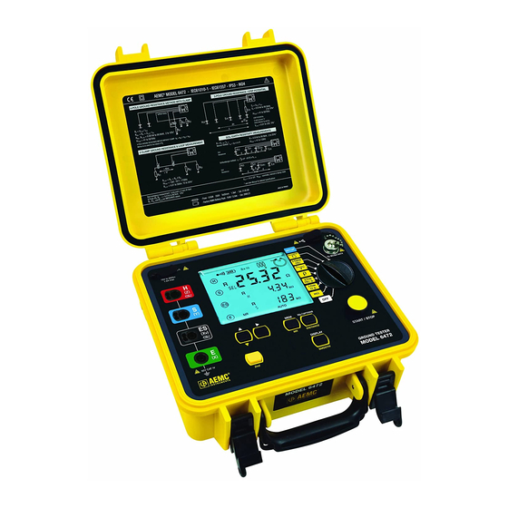
- Page 1 6472 DIGITAL GROUND RESISTANCE AND SOIL RESISTIVITY TESTER E N G L I S H User Manual...
- Page 2 The recommended calibration interval for this instrument is 12 months and begins on the date of receipt by the customer. For recalibration, please use our calibration services. Refer to our repair and calibration section at www.aemc.com. Serial #: ________________________________ Catalog #: ______________________________ Model #:...
- Page 3 READ CAREFULLY BEFORE USING FOR THE FIRST TIME Your instrument is equipped with a NiMH battery. This technology offers several advantages: • Long battery charge life for a limited volume and weight. • Possibility of quickly recharging your battery. • Significantly reduced memory effect: you can recharge your battery even if it is not fully discharged.
-
Page 4: Table Of Contents
Earth/Ground Measurements with 2 Clamps ......22 Data Storage ..................22 Power ....................22 Mechanical ..................23 Environmental ..................23 Safety ....................24 4. OPERATION .................. 25 General Operating Instructions ............25 4.1.1 Automatic Mode ..............25 4.1.2 Manual (Expert) Mode ............25 Instrument Configuration (SET-UP mode) .........26 Ground Resistance Tester Model 6472... - Page 5 3-Pole Earth/Ground Measurement & Coupling ........49 6.4.1 3-Pole Earth/Ground Measurements ........49 6.4.2 Earth/Ground Coupling Measurements ........49 4-Pole Earth/Ground Measurements ..........51 Soil Resistivity Measurements ............51 Earth/Ground Potential Measurements ..........51 Measurements with Two Clamps ............51 SWEEP Mode ..................52 6.10 Smoothing ..................52 Ground Resistance Tester Model 6472...
- Page 6 10.1.4 Out of Limits Indicators ............65 10.1.5 Error Messages ..............67 APPENDIX A: GLOSSARY OF TERMS........... 68 Basic Terminologies ..................68 Glossary ......................69 Repair and Calibration ............... 72 Technical and Sales Assistance ............72 Limited Warranty ................73 Warranty Repairs ................73 Ground Resistance Tester Model 6472...
-
Page 7: Introduction
• NOTE: The potentials on the various rods used for an earth measurement may be different if a nearby electrical installation is defective or certain weather conditions prevail (thunderstorms). It is up to the operator to decide whether to continue or postpone measurements in these situations. Ground Resistance Tester Model 6472... -
Page 8: International Electrical Symbols
Save the damaged packing container to substantiate your claim. 1.4 Ordering Information Ground Resistance Tester Model 6472 .........Cat. #2135.51 Includes carrying bag, 110/240V power adapter with US power cord, optical USB cable, rechargeable NiMH battery pack, and a USB stick with DataView software, ground tester ®... -
Page 9: Kits, Accessories And Replacement Parts
Ground Resistance Tester Model 6472 Kit (150 ft) ......Cat. #2135.52 Includes meter, two carrying bags, two 150 ft color-coded leads on spools (red/blue), one 30 ft lead (green), two 5 ft color-coded leads (red/blue), 110/240V power adapter with US power... - Page 10 AC Current Probe Model MN82............Cat. #2135.71 AC Current Probe Model SR182 ............Cat. #2135.72 Replacement - Connection Lead for Models 6472/6474* ....Cat. #2135.75 Replacement - Fuse, set of 5, 0.63A 250V 5x10 1.5kA ....Cat. #2135.81 Replacement - Calibration Loop ............Cat. #2135.82 Safety Alligator Clip - Black (Rated 600V CAT IV, 10A) ....Cat.
-
Page 11: Product Features
The Model 6472 is CAT IV rated to 50V and is over voltage protected to more than 250V against accidental connection to live circuits. The voltage is also displayed on screen. -
Page 12: Key Features
The Model 6472 is powered by 9.6V, 3.5 Ah NiMH rechargeable batteries. An ex- ternal recharger powered from 120/230V, 50/60Hz is included and provides for testing while recharging. The Ground Resistance Tester Model 6472 is rugged, easy-to-use and ideal for maintenance crews performing numerous tests. -
Page 13: Control Features
Rotary switch: OFF position, 7 measurement functions (see § 5 and 6) and SET-UP function (see § 4.2). START/STOP button: Starts the measurement and compensates for the leads (in the mΩ measurement function - see § 5.2.1). Six function buttons - see § 2.5 Ground Resistance Tester Model 6472... -
Page 14: Display
If this symbol blinks during an active measurement, the limits of use have been exceeded. If the symbol appears constant during an active measurement, the values to be measured are unstable. Warning buzzer is activated Ground Resistance Tester Model 6472... - Page 15 Indicates that there is recorded data in memory. When blinking, it indi- cates that the results need to be saved by pressing the MEM button. Indicates the instrument is remotely controlled by the RS-232/USB REMOTE interface. Ground Resistance Tester Model 6472...
-
Page 16: Button Functions
SMOOTH: Smooths the display of measurement providing a more SMOOTH stable result. Hz/OPTIONS: Enables configuration of measurement functions. z/OPTIONS/ DISTANCE: Available for soil resistivity and V potential measurements. It DISTANCE allows the setting of values of distances used for Rho (ρ) calculation. Ground Resistance Tester Model 6472... -
Page 17: Specifications
Voltages of more than 75Vrms lead to error message 31 (excessive external voltage) or 32 (voltage measurement overrange). If terminals H (Z) and E (X) are put into contact with the line voltage, the protection fuse will blow. Ground Resistance Tester Model 6472... -
Page 18: Current Measurements
100 to 400Hz Operating error from ± (10% + 2cts) ± (5% + 2cts) ± (3% + 2cts) 0.5 to 100mA Operating error from > 20% ± (10% + 2cts) ± (5% + 2cts) 0.1 to 40.0A Ground Resistance Tester Model 6472... -
Page 19: Dc Resistance Measurements
± (7% + 2cts) 0.1 to 40.0A (1): The Model 6472 cannot detect whether a current clamp SR182 or MN82 is connected. In the case of the MN82 clamp, with currents > 10A and frequencies < 100Hz the instrument will not display any warning messages. -
Page 20: Ac Earth Resistance Measurements
The START button must be pressed for more than 2 s. For frequencies between 41 and 256Hz, the resistance of the auxiliary earth electrodes is measured at the test frequency set. At higher frequencies the resistance is measured at 256Hz. Ground Resistance Tester Model 6472... - Page 21 Selective 4-Pole earth resistance measurement with SR182 or MN82 clamp Same characteristics as 4-Pole earth measurements with the following particular conditions: Minimum current: SR182, I >0.5mA MN82, I >2mA Maximum R ratio: SR182, (R ) <500 MN82, (R ) <120 with R <20Ω Ground Resistance Tester Model 6472...
-
Page 22: Soil Resistivity Measurement Ρ
≤ 20,000 electrode S-ES is the resistance of the earth rods R assumed to be identi- ρ ρ ρ ρ cal. Note: With a test voltage U of 16V, halve the value of R Ground Resistance Tester Model 6472... -
Page 23: Earth/Ground Potential Measurements V Pot
41 to 1025 ± (5% + 4cts) 3 to 60kΩ 1 to 3kΩ 41 to 512 > 10mV 3 to 10kΩ 41 to 128 Note: With a test voltage U of 16V, halve the value for R Ground Resistance Tester Model 6472... -
Page 24: Earth/Ground Measurements With 2 Clamps
Memory Capacity: 512 test results (64kB) Communication: Optically isolated USB 3.4 Power Power Source: Rechargeable 9.6V, 3.5Ah NiMH Battery Pack Power Supply: 110/220, 50/60Hz external charger with 18V , 1.9A output or vehicle power Fuse: 0.63A, 250V, 5x20mm, 1.5kA Ground Resistance Tester Model 6472... -
Page 25: Mechanical
(1): This range corresponds to the one defined by standard EN 61557, for which an operating error including the quantities of influence is defined. When the device is used outside this range, 1.5%/10°C and 1.5% between 75 and 90% RH must be added to the operating error. Ground Resistance Tester Model 6472... -
Page 26: Safety
Electrical safety according to EN 61010-1 (Ed. 2 of 2001) Measurement according to EN 61557 (Ed. 2 of 2007) parts 1, 4 and 5. CAT IV, 50V Pollution Degree 2 *Specifications are subject to change without notice Ground Resistance Tester Model 6472... -
Page 27: Operation
Understanding Ground Resistance Testing Workbook CD that was included with the instrument. 4.1 General Operating Instructions The Model 6472 has operating modes: • Automatic mode for routine applications. • Manual (Expert) mode in which the user can change the parameters of the measurement functions. -
Page 28: Instrument Configuration (Set-Up Mode)
4.2 Instrument Configuration (SET-UP mode) To configure the Model 6472 parameters, turn the rotary switch to SET-UP: • All the segments on the display are activated for 1 second and then the “PUSH button” message appears on the display. -
Page 29: Automatic Mode
This setting is retained when the unit is turned off. 5.2 Resistance Measurement mΩ (2-Wire) WARNING: Before performing the resistance test, verify that the sample under test is not energized. Set the switch to Connect the resistance to terminals H (Z) and E (X). Ground Resistance Tester Model 6472... -
Page 30: Lead Compensation Measurement
The 6472 makes a measurement with a positive current (R+), then reverses the direction of the current and makes another measurement with negative (R-). ± ± Ω Ω (R+) + (R-) ALARM ALARM Ω Ω Ω Ω AUTO AUTO To display the measurement parameters, press DISPLAY several times. -
Page 31: Alarm Function
Turn the alarm Access the Choose a low (<) or ON or OFF type of alarm high (>) alarm Set the value of the alarm Complete the adjustment between 1 and 999Ω of the alarm setting Ground Resistance Tester Model 6472... -
Page 32: Resistance Measurement Mω (4-Wire)
(H, S, ES and E will all blink) Hz/OPTIONS again WARNING: Before performing the resistance test, verify that the sample under test is not energized. Set the switch to Connect the resistance to all 4 terminals. Ground Resistance Tester Model 6472... -
Page 33: Earth/Ground Measurement (3-Pole)
H (Z) and E (X) should be 8 to 10 times the depth of the rod you are testing. H (Z) S (Y) Ω Ω distance d - 62% d distance A > 80 m Ground Resistance Tester Model 6472... - Page 34 It is also necessary to program distance A. This is done in the same way as for distance d. Start the measurement by pressing the START/STOP button. EARTH Ω AUTO AUTO To display the measurement parameters, press DISPLAY several times. Ground Resistance Tester Model 6472...
-
Page 35: Full Method
A distinct plateau should result as shown below. R30 R40 % H - E Take the average of the 3 or 4 readings on the R40 + R50 + R60 + R70 plateau to obtain the earth electrode resistance. Ground Resistance Tester Model 6472... -
Page 36: Recommendations For A Reliable Measurement
Avoid routing the connecting cables of the earth electrodes near or parallel to other cables (transmission or supply), metallic conductors, rails, or fences: high test fre- quencies may cause cross-talk and affect the measurements. Ground Resistance Tester Model 6472... -
Page 37: Earth/Ground Measurement (4-Pole)
To measure the resistances of auxiliary electrodes H (Z) and S (Y), or if the resis- tance of the electrodes is too large (see § 10.1), start the measurement with a long press of the START/STOP button. will be displayed. Ground Resistance Tester Model 6472... -
Page 38: Measurements With A Clamp
For this selective earth measurement you need a current clamp, either a Model SR182 or Model MN82 (both available as an accessory). These two types of current clamps are specially designed to work with the 6472 ground tester. The SR182 is more precise, suited to the measurement of higher currents (up to... - Page 39 To measure the resistances of auxiliary electrodes H (Z) and S (Y), or if the resis- tance of the electrodes is too large (see § 10.1), start the measurement with a long press of the START/STOP button. will be displayed. Ω kΩ > 2s kΩ AUTO Ground Resistance Tester Model 6472...
-
Page 40: Soil Resistivity Measurements ( Ρ Position)
In general, interpretations In general, interpretations based on DC soundings based on DC soundings will be limited to simple, will be limited to simple, horizontal; layered horizontal; layered structures structures. Source: DC Resistivity - T. Boyd Ground Resistance Tester Model 6472... -
Page 41: Changing The Measurement Method
The distance can be programmed before or after the measurement. If it is not programmed, only the value of R will be displayed, since the value of ρ remains S-ES indeterminate. Set the switch to Press the 2nd button, then the DISTANCE button. The "hundredths" will blink. Ground Resistance Tester Model 6472... -
Page 42: Wenner Method
< 1/20 d. Distance d must be between 2 and 30m. Connect the cables to the electrodes, then to terminals H (Z), S (Y), ES (Xv), and E (X) in sequence. Program the distance into the instrument as described in § 5.6.3. Ground Resistance Tester Model 6472... - Page 43 (X), or if the resistance of the electrodes is too high (see § 10.1), start the measure- ment by a long press of the START/STOP button. and R , then R and R will be displayed. P-ES ρ ρ Ω Ω > 2s kΩ kΩ kΩ kΩ AUTO AUTO Ground Resistance Tester Model 6472...
-
Page 44: Schlumberger Method
ρ π S-ES To display the measurement parameters, press DISPLAY several times. The device displays the following parameters: , d, U , U-Act (U and its frequency, U and its frequency). ρ S-ES S-ES S-ES Ground Resistance Tester Model 6472... -
Page 45: Potential Measurement (V Pot)
(cables, rails, fences, etc.). Connect the cables to terminals H (Z) and S (Y) and connect terminal E (Z) to the earth. Ground Resistance Tester Model 6472... - Page 46 10. Move electrode S (Y) to distance d2, then reprogram the value of d and make another measurement. Repeat for d3, d4, and d5. 11. Record all of the measurements in order to be able to determine the variation of the earth potential between points H (Z) and E (X). Ground Resistance Tester Model 6472...
-
Page 47: Earth/Ground Measurements With Two Clamps
LOOP NOTE: Use only SR182 or MN82 current clamps, which are specially designed to operate with the Model 6472. Set the switch to Connect a clamp to terminal H (Z) and clamp it to a point down stream from the rod under test that is a serial path to the earth. - Page 48 NOTE: In the AUTO mode, the measurement frequency is 1611Hz. To make an earth measurement that is free of inductive effects, you must change to MANUAL mode and choose a lower measurement frequency (see §6.2). Ground Resistance Tester Model 6472...
-
Page 49: Manual Mode
• Press the Hz/OPTIONS button, then press it again to make the output volt- age (Uout) blink. • Use the ► button to switch to 16 or 32V, then press Hz/OPTIONS again. This setting is retained when the unit is turned off. Ground Resistance Tester Model 6472... -
Page 50: Measurement Frequency Selection
• POS on H and DC+ blinks neg on H and DC- (reversal of polarity at terminal H) In MANUAL mode the tester does not reverse polarity automatically during the measurement; however, the polarity can be reversed during the measurement by pressing the Hz/OPTIONS button. Ground Resistance Tester Model 6472... -
Page 51: Continuity Test
Earth/Ground Coupling Measurements This measurement calls for making and storing 3 intermediate measurements (at the same frequency). It is available only in MANUAL mode. Connection diagram: Measurement # 3 Earth 1 Earth 2 Measurement #1 Measurement #2 Ground Resistance Tester Model 6472... - Page 52 The calculation is based on the following formulas: = (R – R and C To display all of the measurement parameters, press the MR button. • • To scroll through all of the measurements, use the ► and ▲ buttons. then Ground Resistance Tester Model 6472...
-
Page 53: 4-Pole Earth/Ground Measurements
Test voltage blinks Switch between 16 and 32V 6.8 Measurements with Two Clamps Pressing the Hz/OPTIONS button allows the following parameters to be changed using the ► button: • 1611Hz blinks Change the test frequency Ground Resistance Tester Model 6472... -
Page 54: Sweep Mode
In the manual mode, you can activate or deactivate the smoothing of the measure- ment results by pressing the 2nd + DISPLAY (SMOOTH) buttons. This smoothing consists in displaying an exponential mean value, a significant help with highly fluctuating values. Ground Resistance Tester Model 6472... -
Page 55: Memory Function
When you change to SWEEP mode (§ 6.9), the device automatically activates the MEM mode. It offers a memory location before starting the measurement. All of the results obtained will be stored at this location at the end of the measurement. Ground Resistance Tester Model 6472... -
Page 56: Recalling Measurements From Memory
7.3.1 Erasing All Measurements • Set the switch to SET-UP. Push once on the MEM button to display the number of free and available • records. • Push a second time on the MEM button. Ground Resistance Tester Model 6472... -
Page 57: Erasing Selective Measurements
When a test is deleted, its Object/Test number is removed from memory. When you subsequently view stored tests, this number will be skipped. This Object/Test num- ber combination remains unavailable for storing tests until you completely erase memory, as instructed in Section 7.3.1. Ground Resistance Tester Model 6472... -
Page 58: Dataview ® Software
“DataView.” When the DataView folder is open, find the file Setup.exe located in the root directory of the USB drive, and double-click it to run the installation program. The DataView setup screen appears. Figure 8-1 Ground Resistance Tester Model 6472... - Page 59 Spanish) then click Next. (By default, the language selected in step 3 is highlighted.) You are now prompted to select the software you want to install. Each AEMC product family has its own specially designed Control Panel. If you are per- forming a Complete install, by default all available Control Panels are selected (a check mark next to the Control Panel indicates it is selected).
-
Page 60: Ground Tester Control Panel
Control Panel. However, there are situations where using the core Data- View icon may be more convenient for some users, such as when viewing multiple archived reports from different AEMC product families. For further information about using the Ground Tester Control Panel, consult the Help system that comes with the product. -
Page 61: Maintenance
To test this fuse, turn the switch to the mΩ position (2-Wire), connect measurement leads to terminals H (Z) and E (X) and start a measurement. If the unit refuses to operate and the symbol for terminal H (Z) blinks, the fuse must be replaced. Ground Resistance Tester Model 6472... - Page 62 (the four cylindrical holes on the back must slip over the four mounting pins on the front panel). Also make sure you do not pinch the battery leads or other wires or components. Ground Resistance Tester Model 6472...
-
Page 63: Recharging The Battery
(suitable for Europe and the U.S.). The frame of the battery symbol will blink during charging. Charging goes faster when the tester is turned off. The bat- tery voltage is shown on the large display next to Ubatt. Ground Resistance Tester Model 6472... -
Page 64: Replacing The Battery
Battery is too cold for a fast charge (<0°C) - charging at a lower current bAtt FULL Battery is full - switch to trickle charging The 6472 tester can also be recharged from a 12V car outlet with a special charging unit. - Page 65 (3 to 5 times). Discharge cycle (15 H) can be made with the instrument in MANUAL mode, DC 2-Pole (2-Pole) resistance measurement and a short-circuit between H (Z) and E (X) plugs. Ground Resistance Tester Model 6472...
-
Page 66: Troubleshooting
The flashing of terminal S may also indicate that resistance R is too high. The flashing of terminal ES may also indicate that the cur- rent I measured by the clamp is too low. Ground Resistance Tester Model 6472... -
Page 67: Out Of Limits Indicators
After the measurement has started there are indicators of when: • Values R and/or R are too high, • Measurement current I or I is too low, • The instability of the measurement is large. Ground Resistance Tester Model 6472... - Page 68 > 42 V on the terminals of the device. (4) You should change to manual mode and modify the measurement voltage and/or frequency to make a valid measurement (when the NOISE symbol is no longer illuminated). Ground Resistance Tester Model 6472...
-
Page 69: Error Messages
10.1.5 Error Messages When started up, the Model 6472 device automatically performs a self-test. If a fault appears during this self-test or during a measurement, the device displays a message in the form Err XX. There are 3 categories of errors: •... -
Page 70: Appendix A: Glossary Of Terms
Electrode - S (Y) An auxiliary electrode used for measuring the potential of the reference earth. The voltage, which is proportional to the resistance of the earth connection, is measured between this electrode and the earth electrode. Ground Resistance Tester Model 6472... -
Page 71: Glossary
Model 6474 and GroundFlex sensor ® : earth coupling coefficient R with earth R : earth coupling coefficient R with earth R d, A : distances to be programmed to calculate resistivity according to the measuring method used Ground Resistance Tester Model 6472... - Page 72 : second earth value calculated (R : coupling resistance between earths R and R = (R – R ) / 2) : earth resistance connected to terminal E : resistance of the stake connected to terminal H Ground Resistance Tester Model 6472...
- Page 73 In both cases, this value on the display is associated with its frequency. In this case, the resistances of the 4 stakes used for measurement are indicated by R P-ES Ground Resistance Tester Model 6472...
-
Page 74: Repair And Calibration
, Inc. d.b.a. AEMC Instruments ® ® 200 Foxborough Boulevard Foxborough, MA 02035 USA Phone: (800) 343-1391 (508) 698-2115 Fax: (508) 698-2118 E-mail: techsupport@aemc.com www.aemc.com NOTE: Do not ship instruments to our Foxborough, MA address. Ground Resistance Tester Model 6472... -
Page 75: Limited Warranty
Limited Warranty The Model 6472 is warranted to the owner for a period of two years from the date of original purchase against defects in manufacture. This limited warranty is given by AEMC Instruments, not by the distributor from whom it was pur- ®... - Page 76 10/19 99-MAN 100325 v19 Chauvin Arnoux , Inc. d.b.a. AEMC Instruments ® ® 15 Faraday Drive • Dover, NH 03820 USA • Phone: (603) 749-6434 • Fax: (603) 742-2346 www.aemc.com...
Need help?
Do you have a question about the 6472 and is the answer not in the manual?
Questions and answers