Table of Contents
Advertisement
Quick Links
Advertisement
Table of Contents

Related Manuals for AEMC OX 5042


Summary of Contents for AEMC OX 5042
- Page 1 Oscilloscope Model OX 5042 Quick Start Guide ENGLISH www.aemc.com...
-
Page 2: Statement Of Compliance
The recommended calibration interval for this instrument is 12 months and begins on the date of receipt by the customer. For recalibration, please use our calibration services. Refer to our repair and calibration section at www.aemc.com. Serial #: ________________________________ Catalog #: Model #:... -
Page 3: Shipping Contents
PRODUCT PACKAGING 2150.21 Shipping Contents: (1) U.S. Wall Plug 18W, Handscope Oscilloscope 100-240V, 50/60Hz (2) Probe 10:1 600V/BNC-M Model OX5042 Cat. #5000.51 Cat. #5000.50 (1) USB Drive (1) Set of two, color-coded probes (1) USB Cable + Driver (software and manual) Cat. - Page 4 PRODUCT PACKAGING 2150.22 KIT Shipping Contents: (1) U.S. Wall Plug 18W, (1) Probe 10:1 600V/BNC-M Cat. #5000.50 Handscope Oscilloscope 100-240V, 50/60Hz Model OX5042 Cat. #5000.51 (1) USB Drive (1) Set of two, color-coded probes (1) USB Cable + Driver (software and manual) Cat.
- Page 5 PRODUCT PACKAGING 2150.23 KIT Shipping Contents: (1) U.S. Wall Plug 18W, (1) Probe 10:1 600V/BNC-M Cat. #5000.50 Handscope Oscilloscope 100-240V, 50/60Hz Model OX5042 Cat. #5000.51 (1) USB Drive (1) Set of two, color-coded probes (1) USB Cable + Driver (software and manual) Cat.
-
Page 6: Precautions Before Use
Precautions Before Use The operator and/or the responsible authority must carefully read and completely understand the precautions before use. If you use this instrument in an unspecified manner, the protection it ensures can be compromised, thus putting you in danger. •... -
Page 7: Symbols Used
Symbols Used CAUTION! Risk of electric shock. The voltage at the parts marked with this symbol may be dangerous. Warning: Risk of danger. Refer to the operating manual to find out the nature of the potential hazards and the action necessary to avoid such hazards. Earth/Ground Dual insulation The trash can with a line through it means that in the European Union, the prod-... -
Page 8: Channel Isolation
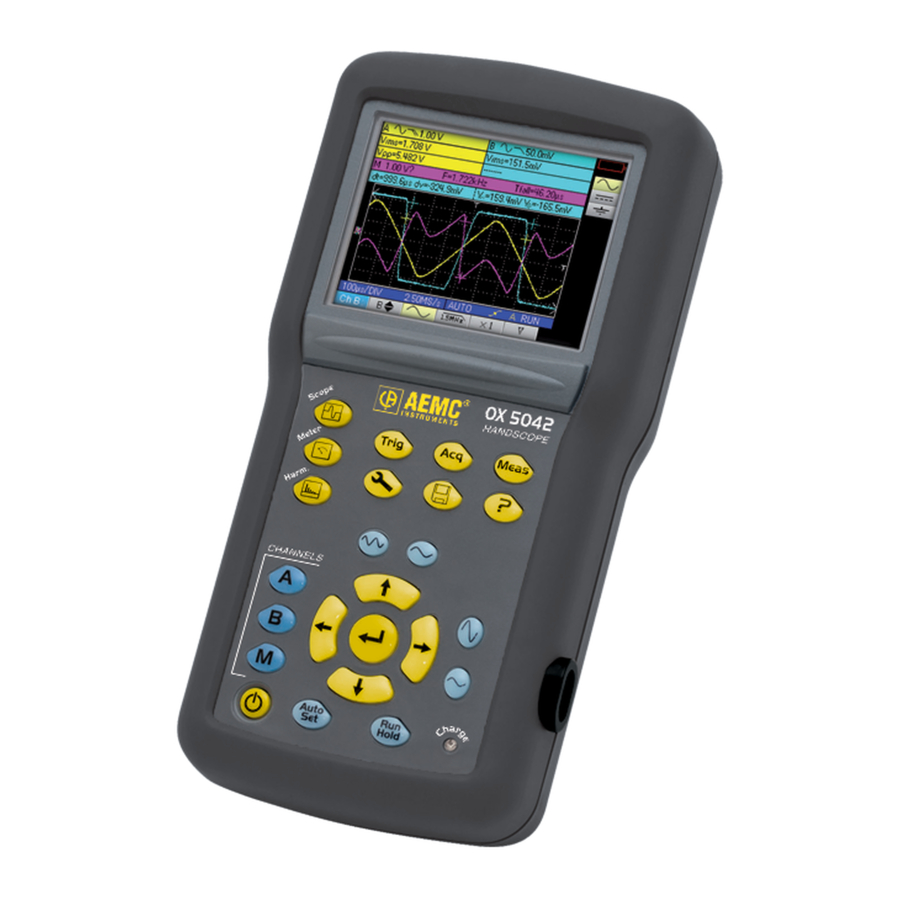
Description The Handscope Oscilloscope Model OX5042-CK combines three instruments into one: • 40MHz oscilloscope • Independent 8000-count multimeter with power measurements • Built-in harmonic analyzer out to the 31st harmonic (fundamental between 40 and 450Hz) The instrument operates at a constant acquisition depth of 2500 points. An LCD TFT screen is used to view the applied signals along with all the setting parameters. -
Page 9: Control Features
Control Features Measurement Terminals Input Channel “B” External Input power Channel “A” supply... - Page 10 ITEM BUTTON DESCRIPTION OPERATING MODE BUTTONS Press these buttons to select the desired operating mode: - Oscilloscope - Multimeter - Harmonic analyzer NAVIGATION BUTTONS Use these navigation buttons to move around the menus and dialog boxes: VERTICAL - Vertical movement and automatic selection in the secondary menus - Adjustment of values in the main menus - Vertical movement in a dialog box HORIZONTAL...
- Page 11 ITEM BUTTON DESCRIPTION OPTICAL COMMUNICATOR - Provides the communication between the oscilloscope and a PC. TIME BASE BUTTONS - increases the time base for acquisition up to 200 s. - decreases the time base for acquisition down to 25 ns. SENSITIVITY BUTTONS - decreases the vertical sensitivity of the last selected channel down to 5mV.
- Page 12 Use of the 10:1 Probes Distribution of stray capacitors: Considering the stray capacitances, it is imperative to correctly connect the reference conductors for each probe The conductors should preferably be connected to the cold points to avoid the transmission of noise by the stray capacitance between modes. The noise of the digital ground (earth) is sent to the analog input by the stray capaci- tance.
-
Page 13: Remote Programming
The calibration output (3Vpp, 1kHz) for the probe is underneath the battery cover. To remove the battery cover, use a coin to turn the slot on the back of the unit counter- clockwise. Connect the probe to be adjusted to the calibration output under the battery housing cover, as shown. -
Page 14: Repair And Calibration
N.I.S.T. (Includes calibration certificate plus recorded calibration data). Ship To: Chauvin Arnoux , Inc. d.b.a. AEMC Instruments ® ®... -
Page 15: Limited Warranty
If a malfunction occurs within the warranty period, you may return the instrument to us for repair, provided we have your warranty registration information on file or a proof of purchase. AEMC® Instruments will, at its option, repair or replace the faulty mate- rial. - Page 16 12/18 99-MAN 100462 v4 Chauvin Arnoux , Inc. d.b.a. AEMC Instruments ® ® 15 Faraday Drive • Dover, NH 03820 USA • Phone: (603) 749-6434 • Fax: (603) 742-2346 www.aemc.com...
Need help?
Do you have a question about the OX 5042 and is the answer not in the manual?
Questions and answers