Table of Contents
Advertisement
DIGITAL GROUND
RESISTANCE TESTERS
GROUND RESISTANCE TESTER
MODEL 3640
Press To
Measure
GROUND RESISTANCE TESTER
MODEL 4610
Press To
Measure
E N G L I S H
X
C1
X-Z
Fault
Xv-Y
Hi Resistance
Xv-Y
Hi Noise
!
REFER TO USER MANUAL
FOR FAULT WARNING LIGHT
EXPLANATIONS
X
X
C1
P1
X-Z
Fault
Xv-Y
Hi Resistance
Xv-Y
Hi Noise
!
REFER TO USER MANUAL
FOR FAULT WARNING LIGHT
EXPLANATIONS
User Manual
3640
4610
Y
P2
AUTORANGING
Y
v
P2
AUTORANGING
Z
C2
Ω
®
I N S T R U M E N T S
Z
C2
Ω
®
I N S T R U M E N T S
Advertisement
Table of Contents

Related Manuals for AEMC 3640


Summary of Contents for AEMC 3640
- Page 1 3640 DIGITAL GROUND RESISTANCE TESTERS 4610 GROUND RESISTANCE TESTER MODEL 3640 Fault Ω Xv-Y Hi Resistance Xv-Y Hi Noise AUTORANGING REFER TO USER MANUAL FOR FAULT WARNING LIGHT Press To EXPLANATIONS Measure ® I N S T R U M E N T S...
- Page 2 The recommended calibration interval for this instrument is 12 months and begins on the date of receipt by the customer. For recalibration, please use our calibration services. Refer to our repair and calibration section at www.aemc.com. Serial #: ________________________________ Catalog #: ______________________________ Model #:...
-
Page 3: Table Of Contents
3.3 Environmental ................. 11 3.4 Safety Specifications .............. 11 3.5 Auto-ranging ................12 4. OPERATION .................. 13 4.1 Grounding Electrode Resistance ..........13 4.1.1 Effect of Ground Electrode Size and Depth on Resistance .............15 4.1.2 Effects of Soil Resistivity on Ground Electrode Resistance ..............16 4.1.3 Factors Affecting Soil Resistivity .........17 4.1.4 Effect of Ground Rod Depth on Resistance ....19 Digital Ground Resistance Tester Model 3640 and 4610... - Page 4 4.9 Soil Resistivity Measurements (Model 4610 Only) ....33 4.10 Soil Resistivity Measurement Procedure (4-Point) ....34 4.11 How to Use 25Ω Calibration Checker ........36 5. MAINTENANCE ................37 5.1 Warning...................37 5.2 Cleaning ..................37 5.3 Replacing the Battery .............37 5.4 Replacing the Safety Fuse ............38 Repair and Calibration ................39 Technical and Sales Assistance ............39 Limited Warranty ...................40 Warranty Repairs ...................40 Digital Ground Resistance Tester Model 3640 and 4610...
-
Page 5: Introduction
Risk of electric shock. The voltage at the parts marked with this symbol may be dangerous. In conformity with WEEE 2002/96/EC Digital Ground Resistance Tester Model 3640 and 4610... -
Page 6: Definition Of Measurement Categories
Ground Resistance Tester Model 3640 Kit (150 ft) ..Cat. #2135.13 Includes ground tester, two 150 ft color-coded leads on spools (red/blue), one 30 ft lead (green), two T-shaped auxiliary ground electrodes, set of 5 spaded lugs, one 100 ft AEMC ®... -
Page 7: Kits, Accessories And Replacement Parts
Ground Resistance Tester Model 4610 Kit (150 ft) ..Cat. #2135.16 Includes ground tester, two 150 ft color-coded leads on spools (red/blue), one 30 ft lead (green), two T-shaped auxiliary ground electrodes, set of 5 spaded lugs, one 100 ft AEMC ®... -
Page 8: Product Features
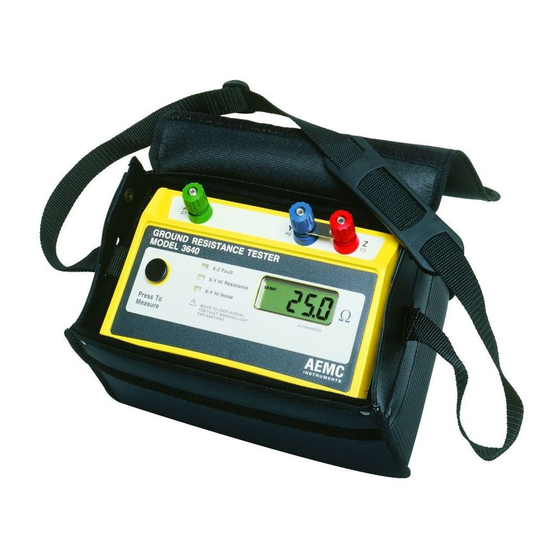
REFER TO USER MANUAL FOR FAULT WARNING LIGHT Press To EXPLANATIONS Measure Figure 1 1. Press-to-Measure button 6. Display 2. Input terminal X (C1) 7. Low battery indicator 3. Input terminal Y (P2) 8. Xv-Y high noise indicator 4. Ground resistance shorting link 9. Xv-Y high resistance indicator 5. Input terminal Z (C2) 10. X-Z fault indicator Digital Ground Resistance Tester Model 3640 and 4610... -
Page 9: 4610 Control And Connector Identification
FOR FAULT WARNING LIGHT Press To EXPLANATIONS Measure Figure 2 1. Press-to-Measure button 7. Display 2. Input terminal X (C1) 8. Low battery indicator 3. Input terminal Xv (P1) 9. Xv-Y high noise indicator 4. Input terminal Y (P2) 10. Xv-Y high resistance indicator 5. Ground resistance shorting link 11. X-Z fault indicator 6. Input terminal Z (C2) Digital Ground Resistance Tester Model 3640 and 4610... -
Page 10: Fault Indicator Leds
• Occasionally, a stray voltage above 6V may also set off this light. • Check the leads for a possible solution. 2.3.3 X-Y High Noise - Xv-Y High Noise (3640) (4610) This LED signals the presence of excessive noise (approx 13V peak) in the voltage circuit (between Xv and Y or X and Y). • One remedy is to use shielded leads from the instrument to the auxiliary electrodes. • Connect all the shields to the rod under test. Digital Ground Resistance Tester Model 3640 and 4610... -
Page 11: Over-Range Indication
• If high electrode resistance still exists after properly inserting aux- iliary electrodes into the earth, try pouring water on and around the auxiliary electrodes. This will improve their electrical connec- tion to earth. • If stray currents are suspected, one solution to reduce their influ- ence is to move both Y and Z electrodes in an arc relative to the X electrode (try, e.g., a 90° shift), and test again. • Display of 0.00: Xv and Y are short-circuited. • Display of <0: X and Z or Xv and Y rods are reversed. NOTE: Accuracy may be affected by auxiliary ground rod (Ry, Rz) resistance levels and by stray signal levels (earth currents). Digital Ground Resistance Tester Model 3640 and 4610... -
Page 12: Specifications
55%, battery power at 8V, auxiliary resistance at the measurement terminals <200Ω, no stray voltage and a magnetic field from 0 to 40A/m. Power Source: Eight 1.5V “AA” batteries; Alkaline recommended. Battery Life: 1800 15-second measurements Low Battery Indicator: If the “Lo Bat” indicator lights up, the batteries are losing power. The available operating time remaining is 100 15-second measurements (approx). Fuse Protection: High breaking capacity - 0.1A, >250V, 0.25 x 1.25" Digital Ground Resistance Tester Model 3640 and 4610... -
Page 13: Mechanical
Vibration: IEC 68-2-6 Drop Test: IEC 68-2-32 Case Material: UL94 Environmental: O-ring sealed against dust and water to IP50 Environmental Operating Temperature: 14° to 131°F (-10° to 55°C); 0 to 90% RH Storage Temperature: -40° to 158°F (-40° to 70°C); 0 to 90% RH with batteries removed Safety Specifications Electrical: EN 61010-1, CAT lII, Pollution Degree 2, 42V Electromagnetic Compatibility: Emission: EN 50081-1 Immunity: EN 50082-1 *Specifications are subject to change without notice. Digital Ground Resistance Tester Model 3640 and 4610... -
Page 14: Auto-Ranging
Auto-ranging The selection of the measurement current is depending on the resistance to measure. When the instrument is turned ON, the measurement starts on the smallest current range (100µA). If the measurement is between 185 and 1950cts, the range stays the same (100µA). If the measurement is under 185cts, the current is multiplied by 10 (within 10mA max). If it is above 1950cts, the current is divided by 10 (without going under 100µA). This is done to avoid switching back and forth between ranges when you are measuring 190Ω. It is possible to display 190.0 or 190Ω depending on the automatic range selection. Digital Ground Resistance Tester Model 3640 and 4610... -
Page 15: Operation
B) The National Institute of Standard and Technology (N.I.S.T.) has demonstrated that the resistance between the electrode and the surrounding earth is negligible if the electrode is free of paint, grease or other coating, and if the earth is firmly packed. Ground Rod and Clamp Contact Resistance Between Rod and Soil Concentric Shells of Earth Figure 3 Digital Ground Resistance Tester Model 3640 and 4610... - Page 16 The equations for systems of electrodes are very complex and often expressed only as approximations. The most commonly used formula for single ground electrode systems, developed by Professor H. R. Dwight of the Massachusetts Institute of Technology, follows: ρ {(In 4L) -1} π R = resistance in ohms of the ground rod to the earth (or soil) L = grounding electrode length r = grounding electrode radius ρ = average resistivity in ohms-cm Digital Ground Resistance Tester Model 3640 and 4610...
-
Page 17: Effect Of Ground Electrode Size And Depth On Resistance
Depth: As a ground rod is driven deeper into the earth, its resistance is substantially reduced. In general, doubling the rod length reduces the resistance by an additional 40%. 1" dia. 1/2" dia. 35 40 Driven Depth in Feet Ground Resistance Versus Ground Rod Depth Figure 5 Digital Ground Resistance Tester Model 3640 and 4610... -
Page 18: Effects Of Soil Resistivity On Ground Electrode Resistance
2,370 7,000 Clay, shale, gumbo, loam 4,060 16,300 Same, with varying proportions 1,020 15,800 135,000 of sand and gravel Gravel, sand, stones with 59,000 94,000 458,000 little clay or loam Table 1 Digital Ground Resistance Tester Model 3640 and 4610... -
Page 19: Factors Affecting Soil Resistivity
Resistivity, Ω-cm Moisture content, % by weight Top Soil Sandy Loam > 109 > 109 250,000 150,000 165,000 43,000 53,000 18,500 19,000 10,500 12,000 6,300 6,400 4,200 Table 2 The resistivity of the soil is also influenced by temperature. Table 3 shows the variation of the resistivity of sandy loam, containing 15.2% moisture, with temperature changes from 20° to -15°C. In this temperature range the resistivity is seen to vary from 7,200 to 330,000 ohm-centimeters. Digital Ground Resistance Tester Model 3640 and 4610... - Page 20 Seasonal variation of earth resistance with an electrode of 3/4" pipe in rather stony clay soil. Depth of electrode in earth is 3 ft for Curve 1, and 10 ft for Curve 2. In some locations, the resistivity of the earth is so high that low-resistance grounding can be obtained only at considerable expense and with an elab- orate grounding system. In such situations, it may be economical to use a ground rod system of Digital Ground Resistance Tester Model 3640 and 4610...
-
Page 21: Effect Of Ground Rod Depth On Resistance
The Effect of Temperature on the Resistivity of Soil Contining Salt* (sandy loam, 20% moisture; salt 5% of weight of moisture) Temperature °C Resistivity (Ohm-centimeters) 1440 Table 5 *Such as copper sulfate, sodium carbonate and others. Salts must be EPA or local ordinance approved prior to use. 4.1.4 Effect of Ground Rod Depth on Resistance Digital Ground Resistance Tester Model 3640 and 4610... - Page 22 4000 3000 2000 1000 Figure 7 1. Select required resistance on R scale. 2. Select apparent resistivity on P scale. 3. Lay straightedge on R and P scale, and allow to intersect with K scale. 4. Mark K scale point. 5. Lay straightedge on K scale point and DIA scale, and allow to intersect with D scale. 6. Point on D scale will be rod depth required for resistance on R scale. Digital Ground Resistance Tester Model 3640 and 4610...
-
Page 23: Ground Resistance Values
NEC . When ® these situations develop, several methods of lowering the ground resis- tance can be employed. These include parallel rod systems, deep driven rod systems utilizing sectional rods and chemical treatment of the soil. Additional methods, discussed in other published data, are buried plates, buried conductors (counterpoise), electrically connected building steel, and electrically connected concrete reinforced steel. Electrically connecting to existing water and gas distribution systems was often considered to yield low ground resistance; however, recent design Digital Ground Resistance Tester Model 3640 and 4610... - Page 24 Potential principle of alternating current (AC) circulating between an auxiliary electrode and the ground electrode under test; the reading will be given in ohms and represents the resistance of the ground electrode to the surrounding earth. AEMC Instruments has also recently introduced a ® clamp-on ground resistance tester. Note: The National Electrical Code and NEC are registered trademarks of the National Fire ® ® Protection Association. Digital Ground Resistance Tester Model 3640 and 4610...
-
Page 25: Ground Resistance Testing Principle
CURRENT SUPPLY AMMETER (I) VOLTMETER (E) GROUND AUXILIARY AUXILIARY ELECTRODE POTENTIAL CURRENT UNDER TEST ELECTRODE ELECTRODE EARTH Figure 8 NOTE: Terminals X and Xv are shorted together in three-point measurement Digital Ground Resistance Tester Model 3640 and 4610... -
Page 26: Position Of The Auxiliary Electrodes In Measurements
On the other hand, if the auxiliary potential rod Y is located outside of the effective resistance areas, as Y is moved back and forth the reading variation is minimal. The readings taken should be relatively close to each other, and are the best values for the resistance to ground of the ground X. The readings should be plotted to ensure that they lie in a “plateau” region as shown in Figure 10. Y Y Y'' Effective Resistance Areas (No Overlap) Reading Variation X-Y Distance Figure 10 Digital Ground Resistance Tester Model 3640 and 4610... -
Page 27: Measuring Resistance Of Ground Electrodes (62% Method)
I N S T R U M E N T S Z Electrode Y Electrode Alligator Clips Ground Rod Figure 12 Consider Figure 13, which shows the effective resistance areas (concentric shells) of the ground electrode X and of the auxiliary current electrode Z. The resistance areas overlap. If readings were taken by moving the auxiliary potential electrode Y towards either X or Z, the reading differentials would be great and one could not obtain a reading within a reasonable band of tolerance. The sensitive areas overlap and act constantly to increase resistance as Y is moved away from X. Digital Ground Resistance Tester Model 3640 and 4610... - Page 28 Under Test Electrode Electrode Effective 62% of D 38% of D Resistance Areas Do Resistance of Not Overlap Auxiliary Current Electrode Resistance of Earth Electrode Distance from Y to Ground Electrode Figure 14 Digital Ground Resistance Tester Model 3640 and 4610...
-
Page 29: Auxiliary Electrode Spacing
10 ft 55 ft 88 ft 12 ft 60 ft 96 ft 18 ft 71 ft 115 ft 20 ft 74 ft 120 ft 30 ft 86 ft 140 ft Table 6 Digital Ground Resistance Tester Model 3640 and 4610... -
Page 30: Ground Resistance Measurement Procedure (3-Point)
Current may be flowing and a dangerous potential could exist between the disconnected wires. • X and Xv (C1, P1) are shorted • Disconnect shorting link between Y and Z (C2, P2) • Connect X to the ground rod to be tested • Connect Y (P2) to the central electrode • Connect Z (C2) to the outer electrode • Depress the “Measure” button to measure ground resistance Digital Ground Resistance Tester Model 3640 and 4610... -
Page 31: Multiple Electrode System
Multiple Electrode System A single driven ground electrode is an economical and simple means of making a good ground system, but sometimes a single rod will not provide sufficient low resistance, and several ground electrodes will be driven and connected in parallel by a cable. Very often when two, three or four ground electrodes are used, they are driven in a straight line. When four or more are used, a hollow square con- figuration is used and the ground electrodes are still connected in parallel and equally spaced (Figure 16). In multiple electrode systems, the 62% method electrode spacing may no longer be applied directly. The distance of the auxiliary electrodes is now based on the maximum grid distance (e.g., in a square, the diagonal; in a line, the total length). A square having a side of 20 ft will have a diagonal of approximately 28 ft. DIAGONAL Figure 16 Digital Ground Resistance Tester Model 3640 and 4610... - Page 32 120 ft 341 ft 550 ft 140 ft 372 ft 600 ft 160 ft 390 ft 630 ft 180 ft 434 ft 700 ft 200 ft 453 ft 730 ft Table 7 Digital Ground Resistance Tester Model 3640 and 4610...
-
Page 33: 2-Point Measurement (Simplified Measurement)
Xv-Y Hi Noise Butt plate AUTORANGING REFER TO USER MANUAL FOR FAULT WARNING LIGHT Press To EXPLANATIONS Measure ® I N S T R U M E N T S Figure 17 Digital Ground Resistance Tester Model 3640 and 4610... -
Page 34: Continuity Measurement
Hi Resistance Xv-Y Hi Noise AUTORANGING REFER TO USER MANUAL FOR FAULT WARNING LIGHT Press To EXPLANATIONS Measure ® I N S T R U M E N T S Figure 19 Digital Ground Resistance Tester Model 3640 and 4610... -
Page 35: Soil Resistivity Measurements (Model 4610 Only)
FOR FAULT WARNING LIGHT Press To EXPLANATIONS Measure ® I N S T R U M E N T S X electrode Xv electrode Y electrode Z electrode b < a Figure 20 Digital Ground Resistance Tester Model 3640 and 4610... -
Page 36: Soil Resistivity Measurement Procedure (4-Point)
= 2πAR), the electrode depth must then be 1/20th of the electrode spacing or 8⅞" (22.5cm). If the electrode depth is greater than 1/20th of the electrode spacing, the following formula must be used: Digital Ground Resistance Tester Model 3640 and 4610... - Page 37 Xv-Y Hi Noise AUTORANGING REFER TO USER MANUAL FOR FAULT WARNING LIGHT Press To EXPLANATIONS Measure ® I N S T R U M E N T S Figure 21 Figure 22 Digital Ground Resistance Tester Model 3640 and 4610...
-
Page 38: How To Use 25Ω Calibration Checker
4.11 How to Use 25Ω Calibration Checker The calibration checker is good for both the 3640 and 4610. It has a resistance of 25Ω. The procedure to use the calibration checker is as follows: • Loosen the X, XV (4610 only), Y and Z terminals. • Insert the resistor as shown in Figure 23. • Tighten down the terminals X, XV (4610 only), Y and Z. -
Page 39: Maintenance
Cleaning NOTE: Disconnect the instrument from any source of electricity. • Use a soft cloth lightly dampened with soapy water. • Rinse with a damp cloth and then dry with a dry cloth. • Do not use alcohol, solvents or hydrocarbons. Replacing the Battery • Loosen the two fastening screws on the battery compartment cover, which is located on the bottom of the case (See Figure 24). • Remove the battery compartment cover to gain access to the eight 1.5V “AA” batteries. • Replace with new batteries and reassemble the instrument. Digital Ground Resistance Tester Model 3640 and 4610... -
Page 40: Replacing The Safety Fuse
NE PAS OUVRIR LE BOITIER AVANT D'AVOIR DECONNECTE TOUTES LES ENTREES Fuse Spare Holder Fuse Holders WARNING DISCONNECT INSTRUMENT FROM ALL INPUTS BEFORE OPENING CASE Battery Compartment Fastening Fastening Screw Screw Figure 24 Digital Ground Resistance Tester Model 3640 and 4610... -
Page 41: Repair And Calibration
NOTE: You must obtain a CSA# before returning any instrument. Technical and Sales Assistance If you are experiencing any technical problems, or require any assistance with the proper operation or application of your instrument, please call, mail, fax or e-mail our technical support team: Chauvin Arnoux , Inc. d.b.a. AEMC Instruments ® ® 200 Foxborough Boulevard Foxborough, MA 02035 USA Phone: (800) 343-1391 (508) 698-2115 Fax: (508) 698-2118 E-mail: techsupport@aemc.com www.aemc.com NOTE: Do not ship Instruments to our Foxborough, MA address. Digital Ground Resistance Tester Model 3640 and 4610... -
Page 42: Limited Warranty
® For full and detailed warranty coverage, please read the Warranty Coverage Information, which is attached to the Warranty Registration Card (if enclosed) or is available at www.aemc.com. Please keep the Warranty Coverage Information with your records. What AEMC Instruments will do: ®... - Page 44 03/10 99-MAN 100143 v14 Chauvin Arnoux , Inc. d.b.a. AEMC Instruments ® ® 15 Faraday Drive • Dover, NH 03820 USA • Phone: (603) 749-6434 • Fax: (603) 742-2346 www.aemc.com...
Need help?
Do you have a question about the 3640 and is the answer not in the manual?
Questions and answers