Table of Contents
Advertisement
Quick Links
Advertisement
Table of Contents

Related Manuals for AEMC 3620


Summary of Contents for AEMC 3620
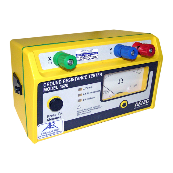
- Page 1 3620 GROUND RESISTANCE TESTER GROUND RESISTANCE TESTER MODEL 3620 X-Z Fault Ω X-Y Hi Resistance X-Y Hi Noise Press To REFER TO USER MANUAL Measure FOR FAULT WARNING LIGHT EXPLANATIONS ® I N S T R U M E N T S...
- Page 2 The recommended calibration interval for this instrument is 12 months and begins on the date of receipt by the customer. For recalibration, please use our calibration services. Refer to our repair and calibration section at www.aemc.com. Serial #: ______________________________ Catalog #: ______________________________...
-
Page 3: Table Of Contents
Table of Contents 1. INTRODUCTION ................3 1.1 International Electrical Symbols ..........4 1.2 Definition of Measurement Categories ........4 1.3 Receiving Your Shipment ............4 1.4 Ordering Information ..............5 1.4.1 Kits, Accessories and Replacement Parts ....5 2. PRODUCT FEATURES ..............6 2.1 Control Features ...............6 2.2 Fault Indicator LEDs ..............7 2.2.1 X-Z Fault ...............7 2.2.2 X-Y High Resistance .............7 2.2.3 X-Y High Noise .............7 2.3 Fault Indicator Tips And Solutions ..........8 3. - Page 4 5. MAINTENANCE ................21 5.1 Warning...................21 5.2 Cleaning ..................21 5.3 Replacing the Battery .............21 5.4 Replacing the Safety Fuse ............22 Repair and Calibration ................23 Technical and Sales Assistance ............23 Limited Warranty ...................24 Warranty Repairs ...................24...
-
Page 5: Introduction
• The instrument must not be operated beyond its specified operating range. • Safety is the responsibility of the operator. • All metal objects or wires connected to the electrical system should be assumed to be lethal until tested. Grounding sys- tems are no exception. • Use extreme caution when using the instrument around ener- gized electrical equipment. • Never attempt to use the instrument to twist or pry the ground electrode or ground wire away from the equipment being grounded. • AEMC Instruments considers the use of rubber gloves to be ® an excellent safety practice even if the equipment is properly operated and correctly grounded. • Always inspect the instrument and leads prior to use. Replace any defective parts immediately. Ground Resistance Tester Model 3620... -
Page 6: International Electrical Symbols
Cat. IV: For measurements performed at the primary electrical supply (<1000V) such as on primary overcurrent protection devices, ripple control units, or meters. Receiving Your Shipment Upon receiving your shipment, make sure that the contents are consistent with the packing list. Notify your distributor of any missing items. If the equip- ment appears to be damaged, file a claim immediately with the carrier and notify your distributor at once, giving a detailed description of any damage. Save the damaged packing container to substantiate your claim. Ground Resistance Tester Model 3620... -
Page 7: Ordering Information
Ground Resistance Tester Model 3620 Kit (150 ft) ..Cat. #2135.10 Includes ground tester, two 150 ft color-coded leads on spools (red/blue), one 30 ft lead (green), two T-shaped auxiliary ground electrodes, set of 5 spaded lugs, one 100 ft AEMC ®... -
Page 8: Product Features
I N S T R U M E N T S Figure 1 1. Press-to-measure button 7. Zero adjustment screw 2. Input terminal X (C1) 8. Low battery indicator 3. Input terminal Y (P2) 9. X-Y hi noise indicator 4. Shorting link 10. X-Y hi resistance indicator 5. Input terminal Z (C2) 11. X-Z fault indicator 6. Display Ground Resistance Tester Model 3620... -
Page 9: Fault Indicator Leds
Y) is too high (approximately 50kW) or that the circuit may be open. Flashing will continue throughout the measurement, even if the resistance drops below the threshold; for example, after reconnecting or lowering auxiliary rod resistance. In this case, you must release the push-button and press again after the fault has been corrected. Occasionally, a stray voltage above 6V may also set off this light. Check the leads for a possible solution. 2.2.3 X-Y High Noise This LED signals the presence of excessive noise (approximately 13V peak) in the voltage circuit (between X and Y). One remedy is to use shielded leads from the instrument to the auxiliary electrodes. Connect all the shields to the rod under test. Ground Resistance Tester Model 3620... -
Page 10: Fault Indicator Tips And Solutions
• If stray currents are suspected, one solution to reduce their influ- ence is to move both Y and Z electrodes in an arc relative to the X electrode (try, e.g., a 90° shift), and test again. NOTE: Accuracy may be affected by auxiliary ground rod (Ry, Rz) resistance levels and by stray signal levels (earth currents). Ground Resistance Tester Model 3620... -
Page 11: Specifications
*Accuracies and specifications are given for an ambient temperature of 23°C ± 3K, RH of 45 to 55%, battery power at 8V, auxiliary resistance at the measurement terminals <200W, no stray voltage and a magnetic field from 0 to 40A/m. Mechanical Dimensions: 8.7 x 5.4 x 5.9" (220 x 136 x 150mm) Weight: 2.9 lbs (1.3kg) Ground Resistance Tester Model 3620... -
Page 12: Environmental
Drop Test: IEC 68-2-32 Case Material: UL94 Environmental: O-ring sealed against dust and water to IP50 Environmental Operating Temperature: 14° to 131°F (-10° to 55°C) Storage Temperature: -40° to 158°F (-40° to 70°C); 0 to 90% RH with batteries removed Relative Humidity: 20 to 90% maximum Safety Specifications Electrical: EN61010-1 Cat lII, Pollution degree 2, 24V Electromagnetic Compatibility: Emission: EN 50081-1 Immunity: EN 50082-1 *All specifications are subject to change without notice Ground Resistance Tester Model 3620... -
Page 13: Operation
Accepted industry standards stipulate that transmission substations should be designed not to exceed one ohm resistance. In distribution substations, the maximum recommended resistance is 5W. In most cases, the buried grid system of any substation will provide the desired resistance. In light industrial or in telecommunications central offices, 5W is often the accepted value. For lightning protection, the arresters should be coupled with a maximum ground resistance of 1W. These parameters can usually be met with the proper application of basic grounding theory. There will always exist circumstances which will make it difficult to obtain the ground resistance required by the NEC . When ® Ground Resistance Tester Model 3620... - Page 14 (AC) circulating between an auxiliary electrode and the ground electrode under test; the reading will be given in ohms and represents the resistance of the ground electrode to the sur- rounding earth. AEMC Instruments has also recently introduced a clamp- ® on ground resistance tester. Note: The National Electrical Code and NEC are registered trademarks of the National Fire ® ® Protection Association. Ground Resistance Tester Model 3620...
-
Page 15: Ground Resistance Testing Principle
If E = 20V and I = 1A, then: R = = = 20 ohms It is not necessary to carry out all the measurements when using a ground tester. The ground tester will measure directly by generating its own cur- rent and displaying the resistance of the ground electrode. CURRENT SUPPLY AMMETER (I) VOLTMETER (E) GROUND AUXILIARY AUXILIARY ELECTRODE POTENTIAL CURRENT UNDER TEST ELECTRODE ELECTRODE EARTH Figure 2 NOTE: Terminals X and Xv are shorted together in three-point measurement. Ground Resistance Tester Model 3620... -
Page 16: Position Of The Auxiliary Electrodes In Measurements
On the other hand, if the auxiliary potential rod Y is located outside of the effective resistance areas, as Y is moved back and forth the reading variation is minimal. The readings taken should be relatively close to each other, and are the best values for the resistance to ground of the ground X. The readings should be plotted to ensure that they lie in a “plateau” region as shown in Figure 4. Y' Y Y'' Effective Resistance Areas (No Overlap) Reading Variation 100% of Distance Between X & Z Figure 4 Ground Resistance Tester Model 3620... -
Page 17: Measuring Resistance Of Ground Electrodes (62% Method)
I N S T R U M E N T S Z Electrode Y Electrode Alligator Clips Ground Rod Figure 5 Consider Figure 6, which shows the effective resistance areas (concentric shells) of the ground electrode X and of the auxiliary current electrode Z. The resistance areas overlap. If readings were taken by moving the auxiliary potential electrode Y towards either X or Z, the reading differentials would be great and one could not obtain a reading within a reasonable band of tolerance. The sensitive areas overlap and act constantly to increase resistance as Y is moved away from X. Ground Resistance Tester Model 3620... - Page 18 Potential Current Under Test Electrode Electrode 62% of D 38% of D Effective Resistance Areas Do Not Overlap Resistance of Auxiliary Current Electrode Resistance of Earth Electrode Distance from Y to Ground Electrode Figure 7 Ground Resistance Tester Model 3620...
-
Page 19: Auxiliary Electrode Spacing
8 ft 50 ft 80 ft 10 ft 55 ft 88 ft 12 ft 60 ft 96 ft 18 ft 71 ft 115 ft 20 ft 74 ft 120 ft 30 ft 86 ft 140 ft Ground Resistance Tester Model 3620... -
Page 20: Ground Resistance Measurement Procedure (3-Point)
I N S T R U M E N T S Z Electrode Y Electrode Alligator Clips Ground Rod -10% 3rd +10% 2nd Measurement Measurement Ground Rod Y Electrode Z Electrode 100% of distance between X and Z Figure 8 Ground Resistance Tester Model 3620... -
Page 21: 2-Point Measurement (Simplified Measurement)
Ground Butt plate X-Y Hi Resistance X-Y Hi Noise Press To REFER TO USER MANUAL Measure FOR FAULT WARNING LIGHT EXPLANATIONS ® I N S T R U M E N T S Figure 9 Ground Resistance Tester Model 3620... -
Page 22: Continuity Measurement
X-Z Fault Ω X-Y Hi Resistance X-Y Hi Noise Press To REFER TO USER MANUAL Measure FOR FAULT WARNING LIGHT EXPLANATIONS ® I N S T R U M E N T S Figure 11 Ground Resistance Tester Model 3620... -
Page 23: Maintenance
WARNING: Disconnect the instrument from any source of electricity. • Use a soft cloth lightly dampened with soapy water. • Rinse with a damp cloth and then dry with a dry cloth. • Do not use alcohol, solvents or hydrocarbons. Replacing the Battery To replace the batteries: • Loosen the two fastening screws on the battery compartment cover, which is located on the bottom of the case (See Figure 12) • Remove the battery compartment cover to gain access to the eight 1.5V “AA” batteries. • Replace with new batteries and reassemble the instrument. Ground Resistance Tester Model 3620... -
Page 24: Replacing The Safety Fuse
0.25 x 1.25") and reassemble the instrument. ATTENTION NE PAS OUVRIR LE BOITIER AVANT D'AVOIR DECONNECTE TOUTES LES ENTREES Fuse Spare Holder Fuse Holders WARNING DISCONNECT INSTRUMENT FROM ALL INPUTS BEFORE OPENING CASE Battery Compartment Fastening Fastening Screw Screw Figure 12 Ground Resistance Tester Model 3620... -
Page 25: Repair And Calibration
NOTE: You must obtain a CSA# before returning any instrument. Technical and Sales Assistance If you are experiencing any technical problems, or require any assistance with the proper operation or application of your instrument, please call, mail, fax or e-mail our technical support team: Chauvin Arnoux , Inc. d.b.a. AEMC Instruments ® ® 200 Foxborough Boulevard Foxborough, MA 02035 USA Phone: (800) 343-1391 (508) 698-2115 Fax: (508) 698-2118 E-mail: techsupport@aemc.com www.aemc.com NOTE: Do not ship Instruments to our Foxborough, MA address. Ground Resistance Tester Model 3620... -
Page 26: Limited Warranty
® For full and detailed warranty coverage, please read the Warranty Coverage Information, which is attached to the Warranty Registration Card (if enclosed) or is available at www.aemc.com. Please keep the Warranty Coverage Information with your records. What AEMC Instruments will do: ®... - Page 28 09/08 99-MAN 100152 v11 Chauvin Arnoux , Inc. d.b.a. AEMC Instruments ® ® 15 Faraday Drive • Dover, NH 03820 USA • Phone: (603) 749-6434 • Fax: (603) 742-2346 www.aemc.com...
Need help?
Do you have a question about the 3620 and is the answer not in the manual?
Questions and answers