
Subscribe to Our Youtube Channel
Related Manuals for Brocade Communications Systems FESX624HF


Summary of Contents for Brocade Communications Systems FESX624HF
- Page 1 HARDWARE INSTALLATION GUIDE Brocade FastIron Edge X-Series Hardware Installation Guide Part Number: 53-1002499-02 Publication Date: 15 June 2017...
- Page 2 The authors and Brocade Communications Systems, Inc. assume no liability or responsibility to any person or entity with respect to the accuracy of this document or any loss, cost, liability, or damages arising from the information contained herein or the computer programs that accompany it.
-
Page 3: Table Of Contents
..............15 FESX624HF and FESX624HFE-PREM6 . - Page 4 ................. . 34 Powering on the system .
- Page 5 ............66 Installing or replacing a 10-Gigabit Ethernet module .
- Page 6 Caution and Danger Notices ....................93 Caution .
-
Page 7: Preface
Preface • Document conventions ................7 •... -
Page 8: Notes, Cautions, And Danger Notices
Preface Brocade resources { x | y | z } A choice of required parameters is enclosed in curly brackets separated by vertical bars. You must select one of the options. In Fibre Channel products, square brackets may be used instead for this purpose. x | y A vertical bar separates mutually exclusive elements. -
Page 9: Contacting Brocade Technical Support
Preface Contacting Brocade Technical Support Contacting Brocade Technical Support As a Brocade customer, you can contact Brocade Technical Support 24x7 online, by telephone, or by e-mail. Brocade OEM customers contact their OEM/Solutions provider. Brocade customers For product support information and the latest information on contacting the Technical Assistance Center, go to http://www.brocade.com/services-support/index.html. - Page 10 Preface Document feedback Brocade FastIron Edge X-Series Hardware Installation Guide Part Number: 53-1002499-02...
-
Page 11: About This Document
About this Document • What’s new in this document ................11 What’s new in this document There is no enhancements in this edition. - Page 12 About this Document What’s new in this document Brocade FastIron Edge X-Series Hardware Installation Guide Part Number: 53-1002499-02...
-
Page 13: Product Overview
FastIron compact products and their supported configurations. TABLE 1 FastIron product family supported configurations Device Standard PREM (Premium) P (POE) IPv6 Devices FESX624E-PREM6 FESX624HFE-PREM6 FESX648E-PREM6 FESX624 FESX624HF FESX648 Brocade FastIron Edge X-Series Hardware Installation Guide Part Number: 53-1002499-02... -
Page 14: Software Features
The following IPv6 models can be upgraded to support either IPv4 routing only or IPv6 and IPv4 routing. For more information, refer to the chapter “Software-based Licensing” in the <Italic>FastIron Configuration Guide. • FESX624 • FESX624HF • FESX648 Brocade FastIron Edge X-Series Hardware Installation Guide Part Number: 53-1002499-02... -
Page 15: Hardware Features
Lnk Act Lnk Act Lnk Act FESX624HF and FESX624HFE-PREM6 The FESX624HF and FESX624HFE-PREM6 have the following ports: • 20 100/1000 Gigabit Ethernet fiber ports for mini-GBIC optical transceivers (also called Small Form Factor Pluggable (SFP) Multisource Agreement (MSA)-compliant optical transceivers). -
Page 16: Fesx648 And Fesx648E-Prem6
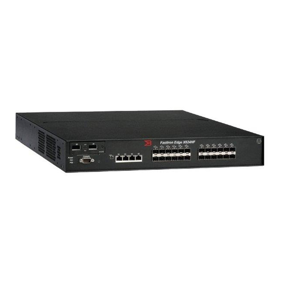
“Combination ports” on page 18. The following figure shows the front panel of the FESX624HF. The FESX624HFE-PREM6 front panel looks similar to the FESX624HF, except for the model number on the front panel. FIGURE 3 FESX624HF front panel... -
Page 17: Reset Button
"Configuring MDI or MDIX" in the <Italic>FastIron Configuration Guide. 100/1000 Mbps ports on Hybrid Fiber (HF) models The 100/1000 ports on the hybrid fiber models (FESX424HF, FESX624HF, and FESX624HFE-PREM6) are configurable to support the interfaces listed in the section “Network interfaces”... - Page 18 Product Overview Hardware features Combination ports One port out of each pair of copper and fiber ports can be active at a time. For example, you can use either copper port 2 or fiber port 2, but not both at the same time. You can use a combination of fiber and copper ports or all copper or all fiber ports, as needed. If you attach both the copper and fiber connectors for a port to the network, the fiber connectors take precedence over the copper connectors.
- Page 19 Traffic is being transmitted and received on the fiber port. No traffic is being transmitted on the fiber port. 100/1000 Fiber Port LEDs on the FESX424HF, FESX624HF, and FESX624HFE-PREM6 Left for upper copper The link is up. Right for lower copper connector The link is down.
-
Page 20: Network Interfaces
Product Overview Hardware features • Ports 13 – 24 • Port 25 – 36 • Port 37 – 48 • Port 49 (optional 10-GbE uplink port) • Port 50 (optional 10-GbE uplink port) Network interfaces Table 3 lists the network interfaces supported on the FastIron compact devices. For network interface and cabling specifications, refer to Table 17 on page 69. -
Page 21: Power Supplies
Product Overview Hardware features Power supplies Each FastIron compact switch comes with one alternating-current (AC) or direct-current (DC) power supply, depending on how it was ordered from the factory. All models have two power supply slots, enabling you to install a second power supply for redundancy. Direct-current (DC) supplies are available for some devices, in which you can use any combination of AC and DC supplies in the same device. - Page 22 Product Overview Hardware features • Power status LEDs are listed in Table 7 on page 26. • Hardware specifications for the power supplies are listed in Chapter 6, “Hardware Specifications”. • “About redundant power supplies and power supply failure” on page 23 POE power supply precautions The following precautions apply to FastIron POE compact switches: •...
-
Page 23: Dc Power Supplies
Product Overview Hardware features FIGURE 6 AC power supply with ON or OFF switch AC Cable AC Power Retainer Connector On/Off Switch Plastic Latch Handle DC power supplies Figure 7 shows a rear view of a FastIron Compact device containing one DC power supply. FIGURE 7 RPS5DC power supply About redundant power supplies and power supply failure... -
Page 24: Cooling System And Fans
Product Overview Hardware features Cooling system and fans This section describes the fans in the FastIron compact switches. FastIron X Series fans The FastIron X Series cooling fans cool the CPU, main memory, and voltage regulators. The fans use either a push or pull configuration to move the air from the left side of the device to the right side of the device. -
Page 25: Installing A Fastiron Compact Switch
The Brocade systems ship with all of the following items. Please review the list below and verify the contents. If any items are missing, please contact the place of purchase. Package contents • Brocade Communications Systems, Inc. FastIron compact switch • 115V AC power cable (for AC sourced devices) •... -
Page 26: Installation Precautions
Installing a FastIron Compact Switch Installation precautions TABLE 1 Summary of installation tasks Task Task Where to Find More Information Number Ensure that the physical environment that will host the device has “Preparing the installation site” the proper cabling and ventilation. page 29 Optionally insert a second or redundant power supply. -
Page 27: General Precautions
Installing a FastIron Compact Switch Installation precautions General precautions All fiber-optic interfaces use Class 1 lasers. Do not install the device in an environment where the operating ambient temperature might exceed 40o C (104o F). Make sure the air flow around the front, sides, and back of the device is not restricted. Never leave tools inside the chassis. - Page 28 Installing a FastIron Compact Switch Installation precautions Ensure that the device does not overload the power circuits, wiring, and over-current protection. To determine the possibility of overloading the supply circuits, add the ampere (amp) ratings of all devices installed on the same circuit as the device. Compare this total with the rating limit for the circuit. The maximum ampere ratings are usually printed on the devices near the input power connectors.
-
Page 29: Preparing The Installation Site
Installing a FastIron Compact Switch Preparing the installation site Remove the power cord from a power supply before you install it in or remove it from the device. Otherwise, the power supply or the device could be damaged as a result. (The device can be running while a power supply is being installed or removed, but the power supply itself should not be connected to a power source.) Disconnect the power cord from all power sources to completely remove power from the device. -
Page 30: Installation Location
Installing a FastIron Compact Switch Installing a redundant power supply Installation location Before installing the device, plan its location and orientation relative to other devices and equipment. Allow at least 3 inches of space at the front of the device for the twisted-pair, fiber-optic, and power cabling. Also, allow a minimum of 3 inches of space between the sides and the back of the device and walls or other obstructions. -
Page 31: Installing A Dc Power Supply
Installing a FastIron Compact Switch Installing a redundant power supply Make sure you insert the power supply right-side up. It is possible to insert the supply upside down, although the supply will not engage with the power backplane when upside down. The power supply is right-side up when the power connector is on the left and the fan vent is on the right. -
Page 32: Installing The Device
The Brocade FastIron compact device supports two different rack mount kits; a kit with short mounting brackets which ships with the device, and a kit with long mounting brackets (19 in.), which you can order separately from Brocade Communications Systems, Inc. (part number 70166-000). - Page 33 Installing a FastIron Compact Switch Installing the device • Four each 12-24 screws to mount the Brocade device to the rack. Make sure the rack or cabinet housing the device is adequately secured to prevent it from becoming unstable or falling over. Mount the devices you install in a rack or cabinet as low as possible.
-
Page 34: Powering On The System
Installing a FastIron Compact Switch Powering on the system FIGURE 2 Attaching the long mounting brackets Mount the device in the rack as illustrated in Figure NOTE Although Figure 3 shows a device with short mounting brackets, the procedure for securing a device with long mounting brackets is the same. -
Page 35: Verifying Proper Operation
Installing a FastIron Compact Switch Verifying proper operation Ensure that all power supplies are fully and properly inserted and no power supply slots are uncovered. Never leave tools inside the device. Remove the power cord from the shipping package. Attach the AC power cable to the AC connector on the rear panel. Insert the power cable plug into a 115V or 120V outlet. -
Page 36: Attaching A Pc Or Terminal
Installing a FastIron Compact Switch Attaching a PC or terminal TABLE 2 LEDs for power Position State Meaning Power Left side of front panel The device is powered on and has enough power to operate. The device is not powered on, or has been powered on but does not have sufficient power to operate. -
Page 37: Troubleshooting The Serial Connection
Installing a FastIron Compact Switch Attaching a PC or terminal If you see one of these prompts, you are now connected to the system and can proceed to “Assigning permanent passwords” page 39. You can customize the prompt by changing the system name. Refer to the <Italic>FastIron Configuration Guide (for FastIron X Series compact devices). - Page 38 Installing a FastIron Compact Switch Attaching a PC or terminal FIGURE 5 Serial port pin assignments showing cable connection options to a terminal or PC DB-9 to DB-9 DB-9 to DB-25 Terminal or PC Terminal or PC Female Switch Female Switch Reserved Reserved Reserved...
-
Page 39: Connecting Network Devices And Checking Connectivity
Connecting Network Devices and Checking Connectivity Overview The procedures in this guide are for qualified service personnel. Table 1 lists the tasks you must perform to connect your Brocade device, and shows where to get troubleshooting information for any problems that can arise. TABLE 1 Network connectivity tasks Step... -
Page 40: Recovering From A Lost Password
Connecting Network Devices and Checking Connectivity Assigning permanent passwords NOTE You must set a super user password before you can set other types of passwords. • Port Configuration – Allows read-and-write access for specific ports but not for global (system-wide) parameters. •... -
Page 41: Configuring Ip Addresses
Connecting Network Devices and Checking Connectivity Configuring IP addresses Configuring IP addresses You must configure at least one IP address using the serial connection to the CLI before you can manage the system using the other management interfaces. In addition, Brocade routers require an IP subnet address for the subnet in which you plan to place them in your network. - Page 42 Connecting Network Devices and Checking Connectivity Configuring IP addresses Configure the IPv4 address and mask address for the interface. Brocade(config)# int e 5 Brocade(config-if-e1000-5)# ip address 192.22.3.44 255.255.255.0 NOTE You can use the syntax ip address <ip-addr>/<mask-bits> if you know the subnet mask length. In the above example, you could enter ip address 192.22.3.44/24.
-
Page 43: Ipv6 Devices
Connecting Network Devices and Checking Connectivity Configuring IP addresses NOTE You do not need to assign a default gateway address for single subnet networks. Syntax: enable [<password>] Syntax: configure terminal Syntax: [no] ip address <ip-addr> <ip-mask> Syntax: [no] ip address <ip-addr>/<mask-bits> Syntax: ip default-gateway <ip-addr>... - Page 44 Connecting Network Devices and Checking Connectivity Configuring IP addresses Configure the IPv6 address and mask address for the interface. Brocade(config)# int e 5 Brocade(config-if-e1000-5)# ipv6 address 2001:200:12D:1300:240:D0FF:FE48:4672:/64 These commands configure the global prefix 2001:200:12d:1300::/64 and the interface ID ::240:D0FF:FE48:4672, and enable IPv6 on interface e 1/5.
-
Page 45: Connecting Network Devices
Connecting Network Devices and Checking Connectivity Connecting network devices NOTE The above procedure shows how to configure an IPv6 address with a manually configured interface ID as the system-wide address for the switch. You could also configure an IPv6 address with an automatically computed EUI-64 interface ID as the system-wide address for the switch. - Page 46 Connecting Network Devices and Checking Connectivity Connecting network devices FIGURE 1 UTP crossover cable UTP Crossover Cable 10/100BaseTX Unused - - Unused Unused - - Unused Unused - - Unused - Unused Unused - FIGURE 2 Cat-5 crossover cable for 1000BaseT Cat-5 Crossover Cable 1000BaseT NOTE...
-
Page 47: Connecting To Workstations, Servers, Or Routers
Connecting Network Devices and Checking Connectivity Connecting network devices Connecting to workstations, servers, or routers Straight-through UTP cabling is required for direct UTP attachment to workstations, servers, or routers using network interface cards (NICs). Fiber cabling is required for direct attachment to Gigabit NICs or switches and routers through fiber ports. Refer to “Connecting a network device to a fiber port”... -
Page 48: Using A Cx4 Transceiver
Connecting Network Devices and Checking Connectivity Connecting network devices Gently insert the fiber optic module into the port until the module clicks into place. The module is keyed to prevent incorrect insertion. Cabling a fiber optic module Complete the following tasks to cable a fiber optic module. Remove the protective covering from the fiber-optic port connectors and store the covering for future use. -
Page 49: Testing Connectivity
Connecting Network Devices and Checking Connectivity Testing connectivity CX4 Transceiver Infiniteband cable CX4 Transceiver Testing connectivity After you install the network cables, you can test network connectivity to other devices by pinging those devices. You also can observe the LEDs related to network connection and perform trace routes. For more information about ping and traceroute commands, refer to the <Italic>FastIron Configuration Guide Observing LEDs After you install the network cables, you can observe certain LEDs to determine if the network connections are functioning properly. -
Page 50: Troubleshooting Network Connections
Connecting Network Devices and Checking Connectivity Troubleshooting network connections TABLE 2 Network connection-related LED states Desired State Meaning Abnormal Meaning or Action State Link (Lnk) On (Green) A link is A link is not established with the remote port. established with You can do the following: •... -
Page 51: Support For Digital Optical Monitoring
Connecting Network Devices and Checking Connectivity Troubleshooting network connections • For fiber-optic connections, verify that the transmit port on the device is connected to the receive port on the connected device, and that the receive port on the device is connected to the transmit port on the connected device. •... - Page 52 Connecting Network Devices and Checking Connectivity Troubleshooting network connections Brocade FastIron Edge X-Series Hardware Installation Guide Part Number: 53-1002499-02...
-
Page 53: Managing The Fastiron Compact Switch
Managing the FastIron Compact Switch Overview This section contains information about refining the configuration of, monitoring, and managing the following components: • Temperature and fan settings for the FESX • Management module CPU usage • MAC address entries (removing) Viewing the device type For the FESX and FESXE, the output of the show chassis command displays the device type. -
Page 54: Fan Speed
Managing the FastIron Compact Switch Managing temperature settings and fan speed on FastIron X Series compact switches • Leave the fan speed as is • Increase the fan speed • Decrease the fan speed • Shut down a module to prevent damage •... -
Page 55: Changing The Temperature Warning Level
TABLE 2 FastIron X Series default warning and shutdown temperatures Device Default Warning Temperature Default Shutdown Temperature FESX624 64°C 80°C FESX624E-PREM6 64°C 80°C FESX624HF 85°C 90°C FESX624HFE-PREM6 85°C 90°C FESX648 80°C 90°C FESX648E-PREM6 80°C 90°C To change the warning temperature on a FastIron X Series compact switch, enter a command such as the following. -
Page 56: Changing The Device Polling Interval
Managing the FastIron Compact Switch Managing temperature settings and fan speed on FastIron X Series compact switches Enter 0 – 125°C for <shutdown-temperature>, which is the high mark on the last (highest) speed supported on the device. Changing the shutdown temperature on a 48-port switch To change the shutdown temperature on a FastIron X Series 48-port switch, enter a command such as the following. -
Page 57: Displaying The Temperature And Temperature Thresholds On A Fastiron X Series 48-Port Switch
Managing the FastIron Compact Switch Managing temperature settings and fan speed on FastIron X Series compact switches FastIron>show chassis Power supply 1 not present Power supply 2 present, status ok Fan 1 ok Fan 2 ok Exhaust Side Temperature Readings: Current temperature : 29.5 deg-C Warning level..: 85.0 deg-C Shutdown level..: 125.0 deg-C... -
Page 58: Displaying Management Module Cpu Usage
Managing the FastIron Compact Switch Displaying management module CPU usage Brocade>show chassis power supply 1 present, status ok power supply 2 not present fan 1 ok Fan 1 speed: slow<->[[medium]]<->fast fan 2 ok Fan 2 speed: slow<->[[medium]]<->fast fan speed switching temperature thresholds: slow ->... - Page 59 Managing the FastIron Compact Switch Removing MAC address entries Use the <mac-address> parameter to remove a specified MAC address from all VLANs. Specify the MAC address in the following format: HHHH.HHHH.HHHH. Use the ethernet <port-num> parameter to remove all MAC addresses for a specified Ethernet port. Use the vlan <number>...
- Page 60 Managing the FastIron Compact Switch Removing MAC address entries Brocade FastIron Edge X-Series Hardware Installation Guide Part Number: 53-1002499-02...
-
Page 61: Replacing And Maintaining The Hardware
The procedures in this guide are for qualified service personnel. The FastIron compact switch requires minimal maintenance for its hardware components. Brocade Communications Systems, Inc. recommends cleaning the fiber-optic connectors on a fiber-optic port and the connected fiber cable each time you disconnect the cable. -
Page 62: Installation Precautions And Warnings
Replacing and Maintaining the Hardware Replacing a power supply Installation precautions and warnings Follow these precautions when installing a power supply in the FastIron switch. Before beginning the installation, refer the precautions in “Power precautions” on page 27. Do not install the device in an environment where the operating ambient temperature might exceed °... -
Page 63: Dc Power Supplies
Replacing and Maintaining the Hardware Replacing a power supply Hold the bar on the front panel of the power supply and pull outward. This will disconnect the power supply from the backplane. Continue to pull the power supply until it is removed from the device. Place the power supply in an anti-static bag for storage. -
Page 64: Removing A Dc Power Supply
Replacing and Maintaining the Hardware Replacing a power supply Removing a DC power supply Complete the following steps to remove a DC power supply. Turn off the DC power source or disconnect it from the power supply. Loosen the three screws used to hold the wires in the connector, then pull out the wires. If necessary, remove the power supply locking screw located in the center rear of the device. -
Page 65: Verifying Proper Operation
Replacing and Maintaining the Hardware Replacing a power supply With one hand, hold the bar on the front panel of the power supply. With the other hand, support the underside of the power supply, and insert the power supply into the empty power supply slot. Press until the supply is completely in the slot, so that the connectors on the back of the supply are fully engaged with the pins on the power backplane. -
Page 66: Installing Or Replacing A 10-Gigabit Ethernet Module
Replacing and Maintaining the Hardware Installing or replacing a 10-Gigabit Ethernet module NOTE The device cannot detect whether the power supplies are of type AC or DC. Thus, the show chassis output will not display this information. Installing or replacing a 10-Gigabit Ethernet module NOTE This section applies to the FastIron X Series compact switches only. -
Page 67: Removing A 10-Gigabit Ethernet Module
Replacing and Maintaining the Hardware Installing or replacing a 10-Gigabit Ethernet module Proceed to the section “Removing a 10-Gigabit Ethernet module” on page 67 or “Installing a 10-Gigabit Ethernet module” page 67. Removing a 10-Gigabit Ethernet module Complete the following steps to remove a 10-Gigabit Ethernet module. Disassemble the FastIron device as instructed in the section “Disassembling the Device”... -
Page 68: Re-Assembling The Device
Replacing and Maintaining the Hardware Replacing a CPU DIMM Re-assembling the device This section provides instructions for re-assembling the FastIron device after removing, installing, or replacing a 10-GbE module. Replace the device’s cover by gently guiding the cover into place, taking care not to bump the connectors for the 10-Gigabit ports. -
Page 69: Removing A Fiber Optic Module
Replacing and Maintaining the Hardware Replacing a fiber optic module Removing a fiber optic module You can remove a fiber SFP (also called a mini-GBIC) or an XFP from a port while the FastIron Compact device is powered on and running. -
Page 70: Installing A New Fiber Optic Module
Replacing and Maintaining the Hardware Cleaning the fiber optic connectors Installing a new fiber optic module You must install a fiber optic module (SFP or XFP transceiver) in each Gigabit Ethernet and 10-Gigabit Ethernet fiber port you want to use. You can install a new fiber optic module in a port while the FastIron Compact device is powered on and running. -
Page 71: Upgrading The Device To Run Layer 3 Software
Replacing and Maintaining the Hardware Upgrading the device to run layer 3 software Upgrading the device to run layer 3 software You can upgrade a FastIron IPv4 device to run Layer 3 code. To do so, follow the instructions in Appendix A, “Layer 3 Upgrade Procedures for FastIron IPv4 devices”. - Page 72 Replacing and Maintaining the Hardware Upgrading the device to run layer 3 software Brocade FastIron Edge X-Series Hardware Installation Guide Part Number: 53-1002499-02...
-
Page 73: Hardware Specifications
14.06 kgs (31 lb) fully loaded, 2.63 in 17.5 in 19.6 in including dual redundant power FESX624E-PREM6 supplies • FESX624HF 10.66 kg (23.5 lbs) empty FESX624HFE-PREM6 FESX648 6.68 cm 44.45 cm 49.78 cm 12.25 kg (27 lbs) fully loaded, including dual redundant power FESX648E-PREM6 2.63 in... -
Page 74: British Thermal Units (Btus)
Hardware Specifications Device specifications British Thermal Units (BTUs) The maximum BTU for and FESX devices is 100 watts (340 BTU/Hr) per power supply. Cooling The cooling fans cool the CPU, main memory, and voltage regulators. The fans use either a push or pull configuration to move the air from the left side of the device to the right side of the device: •... - Page 75 Hardware Specifications Device specifications FIGURE 1 Serial port pin and signalling details Pin Assignment Pin Number Switch Signal Reserved DB-9 mal e TXD (output) RXD (input) Reserved Reserved Reserved Reserved Reserved Most PC serial ports require a cable with a female DB-9 connector. However, terminal connections will vary, requiring a cable with either a DB-9 or DB-25 connector, male or female.
-
Page 76: Cable Specifications
Hardware Specifications Device specifications FIGURE 3 Pin assignment and signalling for 10/100BaseTX and 1000BaseT ports 100BaseTX and 1000BaseT 10BaseT Pin Assignment Pin Number MDI-X ports Pin Number MDI-X ports Not used Not used Not used Not used Cable specifications Table 5 lists the cable specifications for the cables used with the 10/100, Gigabit, and 10-Gigabit Ethernet ports. - Page 77 Hardware Specifications Device specifications NOTE Cable installation and network configuration will affect overall transmission capability. The numbers provided below represent the accepted recommendations of the various standards. For network-specific recommendations, consult your local Brocade reseller TABLE 5 Cable specifications Network Interface Cable Type Connector Type Core...
-
Page 78: Power Cords
Hardware Specifications Device specifications TABLE 5 Cable specifications (Continued) Network Interface Cable Type Connector Type Core Modal Range (meters) Diameter Bandwidth (microns) (MHz*km) or Wavelength (nm) 10GBase-1310 LC connector for 1310 nm up to 200 meters XFP module 10GBase-CX4 Copper CX4 connector for up to 15 meters XFP module... -
Page 79: Power Supply Specifications
Hardware Specifications Power supply specifications Power supply specifications NOTE For an overview of the power supplies, including which power supplies are supported in each FastIron compact switch model, refer to “Power supplies” on page 21. This section contains the following information for the power supplies that ship with the FastIron family of switches: •... -
Page 80: Environmental Considerations
Hardware Specifications Power supply specifications Environmental considerations TABLE 7 Environmental considerations for power supplies Property RPS5, RPS5DC, RPS-X424, and RPS8, RPS8DC, RPSDC-X424-POE, RPSDC-X424 RPS-FGS, RPS-X424-POE, RPS-X448, and RPSDC-X448 Operating Environment ° ° ° ° ° ° ° ° Operating temperature to 40 C, 32 to 104... -
Page 81: Input Connector And Plug
Hardware Specifications Power supply specifications Input connector and plug Table 9 lists the input connectors for the power supplies. TABLE 9 Input connector for power supplies Power Supply Input Connector Properties All AC Power Supplies Standard IEC type (IEC 320) C14 type: UL/CSA 15A/250V, VDE 10A/250V Orientation: Ground pin down All DC Power Supplies... -
Page 82: Regulatory Compliance
Hardware Specifications Power supply specifications FIGURE 5 DC power connector Negative Terminal Screw Positive Terminal Screw 48 RTN Lead - 48 VDC Lead 10 AWG Wire Regulatory compliance This section contains regulatory standards for the power supplies, including the following: •... -
Page 83: Safety Warnings
Hardware Specifications Power supply specifications TABLE 10 EMC and Immunity standards for power supplies Description Certifications Electromagnetic Emissions CISPR 22 Class A FCC Class A VCCI Class A IC ICES-003 Class A (Canada) – (600 watt power supplies only) EN55022 Class A Harmonic Current Emissions (Class A) - EN61000-3-2, with Amendment 14 (1999) Voltage Fluctuations and Flicker - EN61000-3-3... - Page 84 Hardware Specifications Power supply specifications Brocade FastIron Edge X-Series Hardware Installation Guide Part Number: 53-1002499-02...
-
Page 85: Layer 3 Upgrade Procedures For Fastiron Ipv4 Devices
Layer 3 Upgrade Procedures for FastIron IPv4 devices Overview This appendix describes how to upgrade your FastIron IPv4 device to run the full Layer 3 software code. NOTE The procedures in this appendix do not describe how to upgrade IPv6 devices (FESX624 and FESX648) to run the full layer 3 software image. -
Page 86: Installation Overview
Layer 3 Upgrade Procedures for FastIron IPv4 devices Installation overview FIGURE 1 Top cover removal on FastIron compact switches Remove these screws on both sides of the device Rear Front Side Note: If rack mount ears are installed, remove the four screws from each ear. Installation overview You need a Phillips-head screwdriver and an ESD wrist strap to perform this procedure. -
Page 87: Detailed Procedures
Layer 3 Upgrade Procedures for FastIron IPv4 devices Detailed procedures Detailed procedures This section describes how to install the hardware and software contents in the Layer 3 upgrade kit. Hardware installation You need a Phillips-head screwdriver and an ESD wrist strap to perform this procedure. You also need a static-free work area. Complete the following steps to perform the upgrade. - Page 88 Layer 3 Upgrade Procedures for FastIron IPv4 devices Detailed procedures The circular or semicircular indentation on the DIP key indicates the position of lead pin 1. If the DIP key has a circular indentation, it is aligned with pin 1. The semicircular indentation on the DIP key is located on the same end as pin 1. Pin 1 Semicircular indentation Align the semicircular indentation on the DIP key with the semicircular cut-out on the DIP socket.
-
Page 89: Software Installation
Layer 3 Upgrade Procedures for FastIron IPv4 devices Detailed procedures 11. Reinstall the device in its equipment rack, if applicable. 12. Re-insert the power cables to power on the device. 13. Install the software as instructed in the following section. Software installation Use the instructions in this section to install the software after installing a Layer 3 upgrade DIP key. - Page 90 Layer 3 Upgrade Procedures for FastIron IPv4 devices Detailed procedures Verify that the Layer 3 software is present in the flash area you specified by entering the following command. show flash The “Compressed Pri Code size” or “Compressed Sec Code size” line should list the software. If the software is not correct, perform step 2 again.
-
Page 91: Regulatory Statements
Regulatory Statements U.S.A. This equipment has been tested and found to comply with the limits for a Class A digital device pursuant to Part 15 of the FCC Rules. These limits are designed to provide reasonable protection against harmful interference when the equipment is operated in a commercial environment. -
Page 92: Japan Denan Power Cord Statement
Regulatory Statements Japan Denan power cord statement Japan Denan power cord statement English translation of above statement Never use the power cord packed with your equipment for other products. Korea A 급 기기 ( 업무용 방송통신기기 ): 이 기기는 업무용 (A 급 ) 으로 전자파적합등록 을... - Page 93 Caution and Danger Notices Caution A caution calls your attention to a possible hazard that can damage equipment. “Vorsicht” weist auf die Gefahr einer möglichen Beschädigung des Gerätes in. Une mise en garde attire votre attention sur un risque possible d'endommagement de l'équipement. Ci-dessous, vous trouverez les mises en garde utilisées dans ce manuel.
- Page 94 Caution and Danger Notices Caution Table 0.3: CAUTION Make sure the air flow around the front, sides, and back of the device is not restricted. VORSICHT Stellen Sie sicher, dass an der Vorderseite, den Seiten und an der Rückseite der Luftstrom nicht behindert wird.
- Page 95 Caution and Danger Notices Caution Table 0.6: CAUTION All devices with DC power supplies are intended for installation in restricted access areas only. A restricted access area is where access can be gained only by service personnel through the use of a special tool, lock and key, or other means of security, and is controlled by the authority responsible for the location.
- Page 96 Caution and Danger Notices Caution Table 0.8: CAUTION For a DC system (DC power supply part number RPSDC-X424-POE), use a grounding wire of at least 10 American Wire Gauge (AWG). The 10 AWG wire should be attached to an agency-approved crimp connector, crimped with the proper tool. VORSICHT Für ein Gleichstromsystem (Gleichstromnetzteile mit der Teilenr RPSDC-X424-POE) ist ein Erdungsdraht (wenigstens 10 AWG) erforderlich.
- Page 97 Caution and Danger Notices Caution Table 0.10: CAUTION Make sure you insert the power supply right-side up. It is possible to insert the supply upside down, although the supply will not engage with the power backplane when upside down. The power supply is right-side up when the power connector is on the left and the fan vent is on the right.
- Page 98 Caution and Danger Notices Danger Table 0.13: CAUTION If you do not install a module in a slot, you must keep the slot panel in place. If you run the chassis with an uncovered slot, the system will overheat. VORSICHT Falls kein Modul im Steckplatz installiert wird, muss die Steckplatztafel angebracht werden.
- Page 99 Caution and Danger Notices Danger Una peligro le llama la atención sobre cualquier peligro posible que pueda ocasionar daños personales o la muerte. A continuación se dan las advertencias utilizadas en este guide. Table 0.16: DANGER The procedures in this guide are for qualified service personnel. GEFAHR Die Verfahren in diesem Handbuch sind nur für qualifiziertes Wartungspersonal gedacht.
- Page 100 Caution and Danger Notices Danger Table 0.20: DANGER Disconnect the power cord from all power sources to completely remove power from the device. GEFAHR Ziehen Sie das Stromkabel aus allen Stromquellen, um sicherzustellen, dass dem Gerät kein Strom zugeführt wird. DANGER Débranchez le cordon d'alimentation de toutes les sources d'alimentation pour couper complètement l'alimentation du dispositif.
- Page 101 Caution and Danger Notices Danger Table 0.23: DANGER If the installation requires a different power cord than the one supplied with the device, make sure you use a power cord displaying the mark of the safety agency that defines the regulations for power cords in your country.
- Page 102 Caution and Danger Notices Danger Table 0.25: DANGER Before beginning the installation, refer to the precautions in “Power precautions” page 27 GEFAHR Vor der Installation siehe Vorsichtsmaßnahmen unter " Power Precautions " (Vorsichtsmaßnahmen in Bezug auf elektrische Ablagen) auf den Seiten 2 - 4. DANGER Avant de commencer l'installation, consultez les précautions décrites dans "...
Need help?
Do you have a question about the FESX624HF and is the answer not in the manual?
Questions and answers