
Related Manuals for Brocade Communications Systems FastIron SuperX


Summary of Contents for Brocade Communications Systems FastIron SuperX
-
Page 1: Hardware Installation Guide
53-1001723-02 ® 18 March 10 Brocade FastIron X Series Chassis Hardware Installation Guide Supporting Release 07.0.01b... - Page 2 Export of technical data contained in this document may require an export license from the United States government. The authors and Brocade Communications Systems, Inc. shall have no liability or responsibility to any person or entity with respect to any loss, cost, liability, or damages arising from the information contained in this book or the computer programs that accompany it.
-
Page 3: Table Of Contents
Contents About This Document Audience ..........ix Supported hardware and software . - Page 4 Chapter 2 Installing the Chassis Overview ..........41 Summary of installation tasks .
- Page 5 Troubleshooting network connections ......82 Support for digital optical monitoring ..... 83 Chapter 4 Managing the Chassis and Modules Overview .
- Page 6 Replacing a management module......118 Installation precautions.......118 Removing a management module .
- Page 7 Power supply specifications .......170 Physical dimensions and weight ......170 Environmental considerations .
- Page 8 viii Brocade FastIron X Series Chassis Hardware Installation Guide 53-1001723-02...
-
Page 9: About This Document
– IP, RIP, OSPF, BGP, IGMP, PIM, DVMRP, and VRRP. Supported hardware and software The following hardware platforms are supported by this release of this guide: • FastIron SuperX® (FSX) • FastIron SX 800® (FSX 800) •... -
Page 10: Text Formatting
Text formatting The following narrative-text formatting conventions are used in this guide. bold text Identifies command names Identifies the names of user-manipulated GUI elements Identifies keywords Identifies text to enter at the GUI or CLI italic text Provides emphasis Identifies variables Identifies document titles text Identifies CLI output... -
Page 11: Notice To The Reader
CAUTION A Caution statement alerts you to situations that can be potentially hazardous to you or cause damage to hardware, firmware, software, or data. DANGER A Danger statement indicates conditions or situations that can be potentially lethal or extremely hazardous to you. Safety labels are also attached directly to products to warn of these conditions or situations. -
Page 12: Web Access
Web access Go to myBrocade.com, click the Product Documentation tab, then click on the link to the Knowledge Portal (KP) to obtain more information about a product, or to report documentation errors. To report errors, click on Cases > Create a New Ticket in the KP. Make sure you specify the document title in the ticket description. -
Page 13: Product Overview
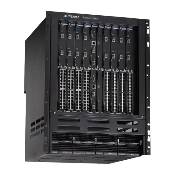
Chapter Product Overview Product overview This chapter contains an overview of the following FastIron X Series® Layer 2 or Layer 3 switches: • FastIron SuperX (FSX) • FastIron SX 800 (FSX 800) • FastIron SX 1600 (FSX 1600) • FastIron SX 1600 Acoustic Noise-Reduced (FSX 1600-ANR) -
Page 14: Poe Port Density
Product overview • Completely separate data and control planes, which results in uncompromised switching performance, increased reliability of both planes, and increased security of the control plane in the event of a Denial of Service (DoS) attack on the data plane. •... -
Page 15: Software Features
Software features TABLE 3 FastIron product family support configurations Device Standard Premium (PREM) Power over Ethernet (POE) FSX 800 FSX 1600 Software features Software features differ depending on the software version that is loaded on the device and the type of management module that is installed in the chassis. Refer to the FastIron Configuration Guide for a complete list of software features supported on your device. -
Page 16: Hardware Features
Hardware features • You cannot mix IPv4 and IPv6 modules together in the same FastIron chassis. • If you install dual IPv6 management modules, the modules must be identical. For example, you cannot install one 2-port management module and one 8-port management module together in the same chassis. - Page 17 FSX chassis. FIGURE 1 FSX chassis 42XG 424F 424C 424C 424C 424C 424C 424F 8X-12GM-4 Even Even Console FastIron SuperX Even Even 424C 424F EJECT EJECT EJECT EJECT AC OK DC OK AC OK DC OK AC OK DC OK...
- Page 18 FSX chassis and the slots into which you can install the various modules and power supplies. FIGURE 2 FSX chassis slots 8X-12GM-4 Even Even Console FastIron SuperX Even Even 424C 424F EJECT AC OK DC OK Slot 1...
-
Page 19: Fsx 800 Chassis
Hardware features FSX 800 chassis The FSX 800 chassis is 6 rack units in height and consists of the following: • Two half slots for the management modules • Two half slots for the switch fabric modules • Eight half slots for the interface modules •... - Page 20 Hardware features Figure 4 shows the FSX 800 Chassis and the slots into which you can install the various modules and power supplies. FIGURE 4 FSX 800 chassis slots 424C 424C 424C 424C 424C 424C 424C 424C 10/100/1000 10/100/1000 Console Console Active Active...
-
Page 21: Fsx 1600 Chassis
Hardware features FSX 1600 chassis There are two versions of the FSX 1600 chassis: • FSX 1600 – Part numbers for chassis and bundles begin with FI-SX-1600-xxx. • FSX 1600 Acoustic Noise-Reduced (ANR) – An enhanced version of the FSX 1600 chassis, part numbers for chassis and bundles begin with FI-SX-1600-ANR-xxx. - Page 22 Hardware features • Two switch fabric modules • A slot panel in each interface module slot and power supply slot that does not currently have a module or power supply installed in it. The slot panel ensures proper airflow within the chassis. •...
- Page 23 Hardware features Figure 6 shows the chassis slots into which you can install the various modules and power supplies. FIGURE 6 FSX 1600 chassis slots 13 15 17 EJECT SYS EJECT SYS AC OK DC OK ALM AC OK DC OK ALM Interface slot 1 Interface slot 2 Interface slot 3...
-
Page 24: Fsx 1600-Anr Chassis
Hardware features Interface slot 8 Management slot 9 10 Management slot 10 11 Interface slot 11 12 Interface slot 12 13 Interface slot 13 14 Interface slot 14 15 Interface slot 15 16 Interface slot 16 17 Interface slot 17 18 Interface slot 18 19 Switch fabric slot 1 20 Switch fabric slot 2... - Page 25 Hardware features Compared to the FSX 1600, the FSX 1600-ANR has improved, redirected airflow, better thermal dissipation, and reduced acoustic noise. The front of the FSX 1600-ANR chassis is identical to the FSX 1600 and both chassis use the same switch fabric, management and interface modules, and power supplies.
-
Page 26: Management Modules
Hardware features The back of the FSX 1600-ANR chassis differs from the FSX 1600 chassis in that the FSX 1600-ANR has an extra sheet metal assembly (ANR kit) and different fan modules. The ANR kit protrudes from the rear of the chassis, making the depth of the FSX 1600-ANR chassis four inches longer than the FSX 1600 chassis. - Page 27 Hardware features NOTE The FSX management module is dedicated, which means that it can be installed in the FSX chassis only. If you attempt to install the FSX management module in the FSX 800, FSX 1600, or other Brocade chassis, the chassis and module will not function properly. Table 4 lists the management modules supported on the FSX chassis.
- Page 28 Hardware features Figure 9 shows the management module’s front panel. FIGURE 9 FSX management module front panel 8X-12GM-4 Even Even Console 10/100/1000 Ethernet copper Gigabit Ethernet fiber The front panel includes the following control features: • A Console port • 12 combination GbE Copper and Fiber ports •...
- Page 29 The existing management networks into which you can connect the Gigabit Ethernet ports must be separate and isolated from the network over which user packets are switched and routed as shown Figure FIGURE 10 Separate management and switching or routing networks FastIron Super X FastIron SuperX Switching and Management EJECT EJECT EJECT...
- Page 30 Hardware features TABLE 5 FSX management module LEDs (Continued) Description and Position State Meaning 10/100/1000 Square LED located on upper On (Green) A link is established with the remote Mbps Copper left corner of upper copper port. Ports ( connector for upper copper Blinking The port is transmitting and receiving connector...
- Page 31 Hardware features Table 6 lists the management modules for the FSX 800 and FSX 1600. TABLE 6 FSX 800 and FSX 1600 management modules Part Number Description Microprocessor MB SDRAM Speed (MHz) IPv4 Management Modules SX-FIZMR no ports SX-FIZMR-PREM SX-FI2XGMR4 two 10-GbE ports SX-FI2XGMR4-PREM SX-FI8GMR4...
- Page 32 Hardware features Figure 11 shows the front panel of the IPv4 and IPv6 management modules with no ports. FIGURE 11 FSX 800 and FSX 1600 management module with no ports 10/100/1000 Console Active Ethernet Figure 12 shows the front panel of the IPv4 and IPv6 management modules with two 10-GbE ports. FIGURE 12 FSX 800 and FSX 1600 management module with two 10-GbE ports 10/100/1000...
- Page 33 Hardware features The 10-GbE ports have optical interfaces with LC connectors for 10-Gigabit Small Form Factor Pluggable (XFP) MSA-compliant transceivers. The transceivers support the fiber optic cabling for LAN PHY listed in Table 32 on page 168. Gigabit Ethernet Ports on the FSX 800 and FSX 1600 8-port management modules The FSX 800 and FSX 1600 8-port management modules come with eight copper and fiber Gigabit Ethernet ports (four copper and four fiber), through which you can connect your device to other network devices at a speed of 1 Gigabit per second.
-
Page 34: Switch Fabric Modules (Fsx 800 And Fsx 1600 Only)
Hardware features TABLE 7 FSX 800 and FSX 1600 management module LEDs (Continued) Description and Position State Meaning Right-most LED above the port. On or Blinking The port is transmitting and receiving traffic. The port is not transmitting or receiving traffic. -
Page 35: Interface Modules
Hardware features LEDs on the switch fabric module The front panel provides status information using the LEDs listed in Table TABLE 8 Switch fabric module LEDs Description and Position State Meaning Top-most LED On (Green) The module is receiving power. The module is not receiving power. - Page 36 Hardware features TABLE 9 Interface modules (Continued) Interface Module Part Number FSX 800 FSX 1600 24-port 100/1000 Hybrid Fiber SX-FI624HF 2-port 10-Gigabit Ethernet LAN SX-FI62XG module Hot swap support • The interface modules are hot swappable, which means you can remove and replace them without powering down the system;...
- Page 37 Hardware features Figure 15 shows the front panel of the IPv4 24-port Gigabit Ethernet copper module. FIGURE 15 IPv4 24-port Gigabit Ethernet copper module front panel 424C POE LEDs Port 1 Port 2 13 Port 13 14 Port 14 24 Port 24 Figure 16 shows the front panel of the IPv6 24-port Gigabit Ethernet copper module.
- Page 38 Hardware features NOTE The POE LEDs work only when POE is enabled on your device. LEDs for 24-port copper module The front panel of the 24-port Gigabit Ethernet copper module includes 24 LEDs that indicate the status of each port, and 24 LEDs (on bottom) that indicate the status of POE. NOTE The POE LEDs work only when POE is enabled on your device.
- Page 39 Hardware features Figure 17 shows the front panel of the IPv4 24-port Gigabit Ethernet fiber module. FIGURE 17 IPv4 24-port Gigabit Ethernet fiber module front panel 424F LEDs Port 1 Port 2 13 Port 13 24 Port 24 The front panel includes the following control features: •...
- Page 40 Hardware features Figure 18 shows the IPv4 100/1000 Hybrid Fiber interface module’s front panel. FIGURE 18 IPv4 100/1000 hybrid fiber interface module front panel 424HF LEDs Port 1 Port 2 13 Port 13 24 Port 24 Figure 19 shows the IPv6 100/1000 Hybrid Fiber interface module’s front panel. FIGURE 19 IPv6 100/1000 hybrid fiber interface module front panel 624HF...
- Page 41 Hardware features The mini-GBIC slots support the 100Base and 1000Base fiber cabling listed in “Network interfaces” on page 30. Support for 100Base-FX on the 100/1000 interface module The 24-port 100/1000 fiber interface module supports the following types of SFPs for 100Base-FX: •...
-
Page 42: Network Interfaces
Hardware features Network interfaces Table 13 lists the network interfaces supported on the FastIron X Series chassis devices. For network interface and cabling specifications, refer to Table 32 on page 168. The output of the show media command displays the type of media installed in the ports. TABLE 13 Network interfaces Interface... -
Page 43: Power Supplies
Hardware features • Ports 1 – 12 • Ports 13 – 24 • 24-port Gigabit Ethernet Fiber Interface Module: • Ports 1 – 12 • Ports 13 – 24 • 2-port 10-Gigabit Ethernet Fiber Interface Module • Port 1 • Port 2 Power supplies The FastIron X Series chassis ships with one or two power supplies, depending on how it was... - Page 44 Hardware features FSX 800 FSX 1600 Sales Model Number Description SX-DCPWR-POE 48-volt DC Supported Supported Supported SX-ACPWR2500-POE 48-volt AC Supported Supported Supported (220-volt input only) For the differences between replacement and original power supplies, refer to “About replacement power supplies” on page 34.
- Page 45 Hardware features CAUTION The POE power supply is designed exclusively for use with the FastIron X Series POE devices. The power supply produces extensive power to support 802.3af applications. Installing the power supply in a device other than the FastIron X Series POE will cause extensive damage to your equipment.
- Page 46 Hardware features The power supplies are hot swappable, which means you can remove and replace them without powering down the system. You can remove and insert a power supply without opening the chassis. If the device contains redundant 12-volt power supplies, you can remove one of the power supplies without interrupting operation.
- Page 47 Hardware features The following illustration shows a side-by-side comparison of the SX-ACPWR-POE replacement power supply and the original power supply. The one on the left is the replacement power supply and the one on the right is the original power supply. FIGURE 25 Side-by-side comparison of SX-ACPWR-POE power supplies Original Power Supply...
- Page 48 Hardware features TABLE 14 Power supply LEDs Desired State Meaning Abnormal State Meaning or Action AC OK (AC ON – Green (steady) The power supply is The power supply is not supply only) receiving AC power from receiving power from an an AC power source AC power source.
- Page 49 Hardware features About redundant power supplies and power supply failure A FastIron chassis with redundant power supplies can maintain full operation when one or more power supplies fail. Power supply failure can be a failure of the supply itself or the office power grid connected to the power supply.
-
Page 50: Cooling System
Hardware features Cooling system The cooling system is contained within the system’s fan tray assembly and modules. The following components comprise the cooling system: • The FSX and FSX 800 each have six four-speed fans. • The FSX 1600 has two five-speed fans in the rear of the chassis. •... -
Page 51: Built-In Mounting Brackets
Layer 3 routing protocol table sizes Alternatively, you can use a rack mount kit (ordered separately) to center-mount the FSX and FSX 800 using two L-shaped mounting brackets. The rack mount kit comes with instructions for installing the mounting brackets and mounting the device in a rack. The FSX 1600 does not have built-in mounting brackets. - Page 52 Layer 3 routing protocol table sizes Brocade FastIron X Series Chassis Hardware Installation Guide 53-1001723-02...
-
Page 53: Overview
Chapter Connecting Network Devices and Checking Connectivity Overview This chapter provides the details for connecting network devices and checking network connectivity. DANGER The procedures in this manual are for qualified service personnel. Table 18 lists the tasks you must perform to connect your Brocade device, and how to troubleshoot any problems that can arise. - Page 54 Assigning permanent passwords • CONFIG – The configuration level. This level lets you configure the system’s IP address and configure switching and routing features. To access the CONFIG mode, you must already be logged into the Privileged level of the EXEC mode. You can set the following levels of Enable passwords: •...
- Page 55 Configuring IP addresses 1. Start a CLI session over the serial interface to the Brocade device. 2. Reboot the device. 3. While the system is booting, before the initial system prompt appears, enter b to enter the boot monitor mode. 4.
- Page 56 Configuring IP addresses CAUTION Use the erase startup-config command only for new systems. If you enter this command on a system you have already configured, the command erases the configuration. If you accidentally do erase the configuration on a configured system, enter the write memory command to save the running configuration to the startup-config file.
- Page 57 Configuring IP addresses IPv4 devices running Layer 2 software To configure an IPv4 address to a device running Layer 2 software, complete the following tasks. 1. At the opening CLI prompt, enter enable. FastIron> enable 2. Enter the following command at the Privileged EXEC level prompt (for example, FastIron#), then press Enter.
- Page 58 Configuring IP addresses IPv6 devices running layer 3 software Before attaching equipment to a Brocade router, you must assign an interface IP address to the subnet on which the router will be located. You must use the serial connection to assign the first IP address.
- Page 59 Configuring IP addresses You must specify the <ipv6-prefix> parameter in hexadecimal using 16-bit values between colons as documented in RFC 2373. You must specify the <prefix-length> parameter in decimal value. A slash mark (/) must follow the <ipv6-prefix> parameter and precede the <prefix-length> parameter. IPv6 devices running Layer 2 software To configure an IPv6 address to a device running Layer 2 software, complete the following tasks.
- Page 60 Connecting network devices Connecting network devices Brocade devices support connections to other vendors’ routers, switches, and hubs, as well other Brocade devices. Cable specifications Refer to “Cable specifications” on page 168 for cable lengths and types. Connecting to Ethernet or fast Ethernet hubs For copper connections to Ethernet hubs, a 10/100Base-TX or 1000Base-T switch, or another Brocade device, a crossover cable is required (Figure 36...
- Page 61 Connecting network devices NOTE The 802.3ab standard (automatic MDI or MDIX detection) calls for automatic negotiation of the connection between two 1000Base-T ports. Therefore, a crossover cable may not be required; a straight-through cable may work as well. For more information about this feature, refer to the FastIron Configuration Guide.
- Page 62 Connecting network devices Connecting to workstations, servers, or routers Straight-through UTP cabling is required for direct UTP attachment to workstations, servers, or routers using network interface cards (NICs). Fiber cabling with LC connectors is required for direct attachment to Gigabit NICs or switches and routers.
-
Page 63: Installing The Management And Interface Modules
Connecting network devices NOTE Some older SFP modules (mini-GBICs for Gigabit Ethernet ports) have latching mechanisms which are larger than the newer parts. These latches could interfere with one another when inserted side by side into a module. Avoid using these mini-GBICs side by side in the same module. These older modules are identified by the number PL-XPL-00-S13-22 or PL-XPL-00-L13-23 above the Serial Number. - Page 64 Connecting network devices Automatic MDI or MDIX detection All 10/100 and Gigabit Ethernet Copper ports on the Brocade FastIron devices support automatic Media Dependent Interface (MDI) and Media Dependent Interface Crossover (MDIX) detection. This feature is enabled on all 10/100 and Gigabit copper ports by default. For each port, you can disable auto MDI or MDIX, designate the port as an MDI port, or designate the port as an MDIX port.
- Page 65 Testing network connectivity Testing network connectivity After you install the network cables, you can test network connectivity to other devices by pinging those devices. You also can observe the LEDs related to network connection and perform trace routes. For more information about ping and traceroute commands, refer to the FastIron Configuration Guide Observing LEDs After you install the network cables, you can observe certain LEDs to determine if the network...
- Page 66 Troubleshooting network connections TABLE 19 Network connection-related LED states Desired Meaning Abnormal State Meaning or Action State Link On (Green) A link is established with A link is not established with the remote the remote port. port. You can do the following: •...
- Page 67 Troubleshooting network connections • Verify that the port has not been disabled through a configuration change. You can use the CLI. If you have configured an IP address on the device, you also can use the Web Management Interface or IronView Network Manager. •...
- Page 68 Troubleshooting network connections Brocade FastIron X Series Chassis Hardware Installation Guide 53-1001723-02...
-
Page 69: Installing The Chassis
Chapter Installing the Chassis Overview This chapter describes hardware installation tasks for the FastIron X Series chassis devices. DANGER The procedures in this manual are for qualified service personnel. NOTE Information about configuring IP addresses and connecting a FastIron X Series chassis device to other network devices is covered in the Chapter 3, “Connecting Network Devices and Checking Connectivity”. -
Page 70: Unpacking A System
Unpacking a system TABLE 15 FSX hardware installation tasks (Continued) Task Number Task Where to Find More Information The chassis ships with a slot panel installed in all “Removing the slot panels” on page 50 module slots that do not currently have a module installed. -
Page 71: Installation Precautions
Installation precautions Installation precautions Follow these precautions when installing the chassis. General precautions DANGER All fiber-optic interfaces use Class 1 Lasers. CAUTION Do not install the device in an environment where the operating ambient temperature might exceed 40 C (104 CAUTION Make sure the air flow around the front, sides, and back of the device is not restricted. -
Page 72: Lifting Precautions
Installation precautions Lifting precautions DANGER A fully populated chassis is heavy. TWO OR MORE PEOPLE ARE REQUIRED WHEN LIFTING, HANDLING, OR MOUNTING THESE DEVICES. DANGER Make sure the rack or cabinet housing the device is adequately secured to prevent it from becoming unstable or falling over. - Page 73 Installation precautions running while a power supply is being installed or removed, but the power supply itself should not be connected to a power source. Otherwise, you could be injured or the power supply or other parts of the device could be damaged. DANGER If the installation requires a different power cord than the one supplied with the device, make sure you use a power cord displaying the mark of the safety agency that defines the regulations...
- Page 74 Installation precautions Ground lug, use UL listed Panduit crimp connector, P/N LCD6-10A, and two 10-32, PPH, screws to secure crimp connector to chassis. The grounding position is located on the side of the chassis adjacent to the ground symbol. CAUTION For the DC input circuit to the system, make sure there is a Listed 30 amp circuit breaker, minimum -48Vdc, double pole, on the input to the terminal block.
-
Page 75: Preparing The Installation Site
Preparing the installation site Preparing the installation site Cabling infrastructure NOTE Ensure that the proper cabling is installed in the site. For information on cabling, refer to the following sections in this guide: • “Attaching a management station” on page 56 •... -
Page 76: Installing A Chassis In A Rack
Installing a chassis in a rack Installing a chassis in a rack Because of the weight of a fully loaded chassis (97 lbs minimum), Brocade recommends mounting a chassis in a rack before installing the modules and power supplies. In a standard 19-inch (EIA310-D) rack, you can install up to seven FSX or FSX 800 chassis devices, or up to three FSX 1600 chassis devices. - Page 77 Installing a chassis in a rack 1. Determine the position of each chassis in the rack. 2. Position two of the four mounting screws for each chassis that you plan to mount in the rack according to the spacings of the keyhole slots on the brackets (as shown in Figure 28).
-
Page 78: Removing The Slot Panels
Removing the slot panels 6. Tighten all screws to secure the chassis in place. Repeat step 3 through step 6 to mount each subsequent chassis in the same rack. FSX 1600 Installing mounting brackets on the chassis The FSX 1600 chassis does not ship with mounting brackets installed. You will need to install the brackets yourself, using a #2 Phillips or flathead screwdriver. - Page 79 Installing the management and interface modules To remove a slot panel, complete the following tasks. 1. Loosen the screws on either end of the slot panel with a #2 Phillips-head or flathead screwdriver. 2. Pull the slot panel out of the chassis, and store it in a safe place for future use. Installing the management and interface modules This section provides the procedures for installing the management and interface modules.
- Page 80 Installing the management and interface modules • An ESD wrist strap with a plug for connection to the ESD connector on the chassis. DANGER For safety reasons, the ESD wrist strap should contain a series 1 meg ohm resistor. • A # Phillips-head or flathead screwdriver.
- Page 81 Installing the management and interface modules The following illustrations show placement of the management and interface modules in the FastIron X Series chassis devices. FIGURE 31 Installing a management module in the FSX chassis FIGURE 32 Installing a management module in the FSX 800 chassis Management module Brocade FastIron X Series Chassis Hardware Installation Guide 53-1001723-02...
- Page 82 Installing the management and interface modules FIGURE 33 Installing a management module in the FSX 1600 chassis Management module Brocade FastIron X Series Chassis Hardware Installation Guide 53-1001723-02...
- Page 83 Installing the management and interface modules FIGURE 34 Installing an interface module in the FSX and FSX 800 chassis Interface module Brocade FastIron X Series Chassis Hardware Installation Guide 53-1001723-02...
-
Page 84: Attaching A Management Station
Attaching a management station FIGURE 35 Installing an interface module in the FSX 1600 chassis Interface module Attaching a management station You can manage the FastIron X Series system in the following ways: • You can connect a PC or terminal to the management module’s serial (Console) port or 10/100/1000 Ethernet port and access the system directly from the PC or terminal, or from a Telnet connection to the PC or terminal. -
Page 85: Attaching A Switch To An Ethernet Port
Attaching a management station NOTE The management network into which you can connect a Gigabit Ethernet port must be separate and isolated from the network over which user packets are switched and routed as shown in Figure 10 on page 17. Attaching a PC or terminal to the console port or 10/100/1000 copper port The management module’s Console port, which has a male DB-9 serial connector, and... -
Page 86: Connecting Ac Power To The Chassis
Powering on the system Powering on the system After you complete the hardware installation, you can power on the system. Verify that all modules and power supplies are fully and properly installed and no module slots are uncovered. Note the following before powering on the system. CAUTION If you do not install a module in a slot, you must keep the slot panel in place. - Page 87 Powering on the system AC 4 AC 3 AC 2 AC 1 Cord retainer Brocade FastIron X Series Chassis Hardware Installation Guide 53-1001723-02...
-
Page 88: Connecting Dc Power To The Chassis
Powering on the system Cord retainer DANGER If the installation requires a different power cord than the one supplied with the device, make sure you use a power cord displaying the mark of the safety agency that defines the regulations for power cords in your country. - Page 89 Powering on the system To perform this task, you need the following items: • Flathead screwdriver • Phillips-head screwdriver • #6 AWG wire (grounding wire) • #8 AWG wire (input wire) • Crimping tool To connect a DC power source,complete the following tasks. 1.
- Page 90 Powering on the system – Ground Brocade FastIron X Series Chassis Hardware Installation Guide 53-1001723-02...
-
Page 91: Verifying Proper Operation
Verifying proper operation Chassis Rear View Detail – Ground DC power 5. Re-attach the transparent cover that was removed in step 6. Connect the wire to your DC power source making sure to connect the positive and negative supply wires to the correct location as marked on the power supply. Observe the LEDs on the power supply front panel. -
Page 92: Observing The Leds
Verifying proper operation Observing the LEDs After the FastIron X Series chassis device powers on, you can observe its LEDs to verify that it initialized successfully. Table 17 outlines the LEDs, the desired state of each LED, possible abnormal states of each LED, and what to do if an LED indicates an abnormal state. TABLE 17 Desired and abnormal LED states after system power on Desired State... - Page 93 Verifying proper operation TABLE 17 Desired and abnormal LED states after system power on (Continued) Desired State Meaning Abnormal Meaning or Action State Interface Module Link or On or blinking A link is established with At this stage of the installation, Activity the remote port and the you have not yet cabled the...
-
Page 94: Displaying The Module Status
Verifying proper operation TABLE 17 Desired and abnormal LED states after system power on (Continued) Desired State Meaning Abnormal Meaning or Action State DC OUT ON – Green (steady) The power supply is The power supply is not supplying DC output power supplying DC output power to to the chassis the chassis. -
Page 95: Support For Digital Optical Monitoring
Verifying proper operation The following shows the output of the show module command when entered on the FSX 800. The display output is similar on the FSX 1600. FastIron SX 800 Switch# show module Module Status Ports Starting MAC F1: SX-FISF Switch Fabric active F2: SX-FISF Switch Fabric active... - Page 96 Verifying proper operation Brocade FastIron X Series Chassis Hardware Installation Guide 53-1001723-02...
-
Page 97: Overview
Chapter Managing the Chassis and Modules Overview This chapter contains information about refining the configuration of, monitoring, and managing the hardware components. Displaying chassis status and temperature readings You can display the following information related to the Brocade chassis: • Status of the power supplies •... - Page 98 Displaying chassis status and temperature readings FastIron SX 800 Router#show chassis Chassis Type: FastIron SX 800 Power supply 1 not present Power supply 2 not present Power supply 3 (H1250C - AC - Regular) present, status ok Power supply 4 not present Fan 1 ok, speed (auto): 1<->[[2]]<->3<->4 Fan 2 ok, speed (auto): 1<->[[2]]<->3<->4 Fan 3 ok, speed (auto): 1<->[[2]]<->3<->4...
- Page 99 Displaying chassis status and temperature readings The following shows example output of the show chassis command on the FSX 1600. FastIron SX 1600 Router#show chassis Chassis Type: ANR-FastIron SX 1600-PREM (ANR: Acoustic Noise-Reduced) Power supply 1 not present Power supply 2 not present Power supply 3 not present Power supply 4 (32005100 - AC - Regular) present, status ok Power supply 5 not present...
- Page 100 TABLE 20 Chassis status and temperature information This Field... Displays... Chassis Type This field displays the chassis type. For example: • FastIron SuperX • FSX 800 • FSX 1600 • ANR-FSX 1600-PREM ANR indicates that the chassis has Accoustic Noise Reduction. For more information about the ANR chassis, refer to “FSX 1600 chassis”...
- Page 101 Displaying chassis status and temperature readings TABLE 20 Chassis status and temperature information (Continued) This Field... Displays... Fans Fan <number> For the FSX and FSX 800, this field displays formation about fans 1 through 6. Fan locations are as follows: •...
-
Page 102: Managing The Cooling System
Managing the cooling system TABLE 20 Chassis status and temperature information (Continued) This Field... Displays... Fan speed switching The FSX displays the configured temperature thresholds for the management and temperature thresholds interface modules. • Rule 1/2 (MGMT CARDS THERMAL PLANE) – The configured temperature threshold for the management module. - Page 103 Managing the cooling system • Thermal Plane 2 (also called Rule 2/2) – This thermal plane includes all of the temperature sensors on all of the Interface modules. Each Interface module has one temperature sensor. The FSX 800 and FSX 1600 have three thermal planes: •...
- Page 104 Managing the cooling system Changing temperature thresholds for thermal planes and fan speeds The cooling system in the FSX and FSX 800 include six four-speed fans. The fans operate at speeds of low, medium-low, medium, and high. In general, each fan speed, except for low, has a low and high temperature threshold associated with it as shown in Figure 38.
- Page 105 Managing the cooling system Table 21 outlines the default low and high temperature thresholds for each fan speed, as well as the operating level and noise level of the fans at each fan speed. TABLE 21 Default low and high temperature thresholds for thermal planes and fan speeds Fan Speed Description...
- Page 106 Managing the cooling system Fan Speed Low Temperature Threshold High Temperature Threshold High 67 C 82 C Medium-high 57 C 72 C However, the Brocade device will not accept the following values because the low temperature threshold for the high speed (73 C) is higher than the high temperature threshold (72C) for the medium-high speed.
-
Page 107: Manually Setting The Fan Speed
Managing the cooling system FastIron# show chassis Fan speed switching temperature thresholds: Rule 1/3 (MGMT CARDS THERMAL PLANE): Speed 1: NM<----->57 deg-C Speed 2: 48<----->58 deg-C Speed 3: 49<----->59 deg-C Speed 4: 50<----->80 deg-C (shutdown) Rule 2/3 (LINE CARDS THERMAL PLANE): Speed 1: NM<----->57 deg-C Speed 2:... -
Page 108: Monitoring The Cooling System
Managing the cooling system Typically, the temperature of the thermal planes, in conjunction with the settings of low and high temperature thresholds, determine the speed of the fans. If desired, you can use the fan-speed command to manually set the speed of the fans. For example, to set the speed of all fans to low, enter the following command. - Page 109 Managing the cooling system Displaying fan status and speed The show chassis command displays the status and speed of the fans in the Brocade chassis. The following shows an example output. FastIron# show chassis Fan 1 ok, speed (auto): 1<->[[2]]<->3<->4 Fan 2 ok, speed (auto): 1<->[[2]]<->3<->4 Fan 3 ok, speed (auto): 1<->[[2]]<->3<->4 Fan 4 ok, speed (auto): 1<->[[2]]<->3<->4...
-
Page 110: Displaying The Syslog Configuration And Static And Dynamic Buffers98
Displaying the Syslog configuration and static and dynamic buffers Displaying the Syslog configuration and static and dynamic buffers For information about configuring Syslog, refer to the FastIron Configuration Guide. To display the Syslog parameters currently in effect on a system, enter the following command from any level of the CLI. -
Page 111: Syslog Messages For Pci (Hardware) Errors
Syslog messages for PCI (hardware) errors The message types that appear in the static buffer do not appear in the dynamic buffer. The dynamic buffer contains up to the maximum number of messages configured for the buffer (50 by default), then begins removing the oldest messages (at the bottom of the log) to make room for new ones. -
Page 112: Displaying Management Module Cpu Usage
Displaying management module CPU usage FastIron# disable switch-fabric 1 Syntax: disable switch-fabric 1 | 2 where switch-fabric 1 is the left-most module in the FSX 800 chassis and the top-most module in the FSX 1600 chassis, and switch-fabric 2 is the right-most module in the FSX 800 chassis and the bottom-most module in the FSX 1600 chassis. -
Page 113: Removing Mac Address Entries
Removing MAC address entries Removing MAC address entries You can remove learned MAC address entries from the Brocade system’s MAC address table. You can remove the following: • All MAC address entries. • All MAC address entries for a specified Ethernet port. •... - Page 114 Removing MAC address entries Brocade FastIron X Series Chassis Hardware Installation Guide 53-1001723-02...
-
Page 115: Using A Redundant Management Module
Chapter Using a Redundant Management Module Overview NOTE This chapter applies to the FSX 800 and FSX 1600 chassis devices only. You can install a redundant management module in the FSX 800 and FSX 1600 chassis. By default, the system considers the module installed in the lower-numbered slot to be the active management module, and the module installed in the higher-numbered slot to be the redundant or standby module. -
Page 116: Management Module Switchover
How Management module redundancy works After the modules boot, the active module synchronizes the standby module’s flash code and system-config file with its own. During normal operation, the active module handles tasks such as obtaining network topology and reachability information and determining the best paths to known destinations. The active module also monitors the standby module. -
Page 117: Switchover Implications
How Management module redundancy works Removal and replacement of a management module For information about how to remove and replace a management module, refer to “Replacing a management module” on page 118. This section explains how management module redundancy is affected when you remove and replace an active or standby management module. -
Page 118: Management Module Redundancy Configuration
Management module redundancy configuration Management sessions You can establish management sessions with the active management module’s management port. If a switchover occurs, the management port on the original active module shuts down and all open CLI, Web Management Interface, and IronView Network Manager sessions with that port close. You can open new sessions with the new active module, provided that the new active module has the same management port connections. -
Page 119: Managing Management Module Redundancy
Managing management module redundancy Managing management module redundancy The FSX 800 and FSX 1600 support the following management tasks related to management module redundancy: • Perform immediate synchronization of files • Perform a manual switchover to the standby module • Reboot the standby module File synchronization between the active and standby management modules... -
Page 120: Manually Switching Over To The Standby Management Module
Managing management module redundancy Figure 39 shows how the files are synchronized between the active module and the standby module. FIGURE 39 Active and standby management module file synchronization Synchronized at startup or switchover Also can be immediately synchronized using the CLI Startup-config also automatically updated with write memory... -
Page 121: Rebooting The Active And Standby Management Modules
Hitless management support Once you enter this command, the system will prompt you as follows. Are you sure? (enter ’y’ or ’n’): y Running Config data has been changed. Do you want to continue the switch-over without saving the running config? (enter ’y’ or ’n’): n Please save the running config and try switch-over again Syntax: switch-over-active role Rebooting the active and standby management modules... -
Page 122: What Happens During A Hitless Os Upgrade And Hitless Switchover
Hitless management support What happens during a Hitless OS upgrade and Hitless switchover The following steps describe the internal events that occur during a Layer 2 hitless OS upgrade and hitless switchover. 1. The standby management module resets and reloads with the new software image in its flash memory. -
Page 123: Syslog Message For Hitless Os Upgrade And Hitless Switchover111
Hitless management support Traffic Type Impact Layer 2 switched traffic, including Layer 2 switched traffic is not impacted during a manual switchover. All unicast and multicast existing switched traffic flows continue uninterrupted. New switched flows are not learned by the FastIron switch during the switchover process and are flooded to the VLAN members in hardware. - Page 124 Hitless management support • 802.1p/q • 802.1s MSTP • 802.3ad - LACP • ACL accounting • ACL-based mirroring • All ports and links remain operational • BPDU Guard • Broadcast suppression (to uplink port only) • Dual-mode VLAN • Dynamic buffer allocation •...
- Page 125 Hitless management support • Static MAC and multi-port static MAC • Static trunks • Subnet VLANs • Super Aggregated VLANs (SAV) • System-max parameters • Topology groups • Traffic policies • UDLD • VLAN groups • VSRP NOTE Layer 2 services and protocols that are not listed (not supported by the hitless feature) may encounter disruptions during reset of the management and interface modules, but will resume normal operation once the modules are back up and running.
-
Page 126: Monitoring Management Module Redundancy
Monitoring management module redundancy Monitoring management module redundancy You can monitor the following aspects of management module redundancy: • The status of the management modules (if a module is the active or standby module) • The switchover history for the management modules The following sections explain how you can monitor the management modules Determining management module status You can determine the status of a management module in the following ways:... -
Page 127: Displaying Temperature Information
Monitoring management module redundancy FastIron SX 800 Router# show module Module Status Ports Starting MAC F1: SX-FISF Switch Fabric active F2: SX-FISF Switch Fabric active S1: SX-F424C 24-port Gig Copper 00e0.5200.0100 S5: SX-F424C 24-port Gig Copper 00e0.5200.0160 S9: SX-FI2XGMR4 2-port Management Active 00e0.5200.0100 { Status : OK }... -
Page 128: Displaying Switchover Information
Monitoring management module redundancy Displaying switchover information You can view the system log or the traps logged on an SNMP trap receiver, which includes Information about whether a switchover has occurred. In addition, refer to “Syslog message for Hitless OS upgrade and Hitless switchover” on page 111. -
Page 129: Maintaining The Hardware
Chapter Maintaining the Hardware Overview This chapter provides instructions for maintaining the FastIron X Series chassis hardware. DANGER The procedures in this manual are for qualified service personnel. Hardware maintenance schedule The FastIron X Series chassis requires minimal maintenance for its hardware components. Brocade recommends cleaning the fiber-optic connectors on a fiber-optic port and the connected fiber cable each time you disconnect the cable. -
Page 130: Replacing A Management Module
Replacing a management module Replacing a management module This section provides information about the following tasks: • Removing a management module • Installing a new management module This section provides instructions for removing and installing the management modules in the FSX, FSX 800, and FSX 1600 chassis. -
Page 131: Installing A New Management Module
Replacing a management module • A #2 Phillips-head or flathead screwdriver. To remove a management module from the chassis, perform the following tasks. 1. Refer to “Installation precautions” on page 118. 2. If your Brocade chassis does not have redundant management modules, power down the chassis and remove the power cables from the chassis power supplies. - Page 132 Replacing a management module Use a #2 Phillips-head or flathead screwdriver to tighten the two screws at either end of the management module’s front panel. FIGURE 40 Installing a management module in the FSX chassis FIGURE 41 Installing a management module in the FSX 800 chassis Management module Brocade FastIron X Series Chassis Hardware Installation Guide 53-1001723-02...
-
Page 133: Replacing A Switch Fabric Module (Fsx 800 And Fsx 1600 Only)
Replacing a switch fabric module (FSX 800 and FSX 1600 only) FIGURE 42 Installing a management module in the FSX 1600 chassis Management module FSX 800 FSX 1600 Replacing a switch fabric module ( only) This section provides information about the following tasks: •... -
Page 134: Removing A Switch Fabric Module
Replacing a switch fabric module (FSX 800 and FSX 1600 only) Removing a switch fabric module You can remove a switch fabric module from the chassis while it is powered on and running. Before removing a switch fabric module from the chassis, have the following on hand: •... - Page 135 Replacing a switch fabric module (FSX 800 and FSX 1600 only) 5. Use a #2 Phillips-head or flathead screwdriver to tighten the two screws at either end of the switch fabric module’s front panel. FIGURE 43 Installing a switch fabric module in the FSX 800 Switch Fabric module Brocade FastIron X Series Chassis Hardware Installation Guide 53-1001723-02...
-
Page 136: Replacing An Interface Module
Replacing an interface module FIGURE 44 Installing a switch fabric module in the FSX 1600 Switch Fabric module Replacing an interface module You can remove an interface module and replace it with a new one while the chassis is powered on and running. -
Page 137: Precautions
Replacing an interface module Precautions Note the following when removing and replacing Interface modules: • If you remove an interface module without first disabling it, the chassis will reboot (reload the software). • You do not need to enable an interface module after inserting it in the chassis. The FastIron X Series chassis device automatically enables the module when you insert it into a live chassis or when you power on the chassis. -
Page 138: Removing An Interface Module
Replacing an interface module It is important to wait a minimum of 10 seconds between the removal and insertion of a line module. Re-insertion of a line module less than 10 seconds after the removal of a line module may result in the line module not being properly recognized. Removing an interface module To remove an interface module, first perform the steps in section “Before removing an interface... - Page 139 Replacing an interface module NOTE Before installing one of these modules into the FSX chassis, have the following on hand: • A new interface module, which you can order from Brocade. • An ESD wrist strap with a plug for connection to the ESD connector on the chassis. DANGER For safety reasons, the ESD wrist strap should contain a series 1 meg ohm resistor.
- Page 140 Replacing an interface module NOTE You do not need to enable an interface module after inserting it in the chassis. The FastIron X Series chassis device automatically enables the module when you insert it into a live chassis or when you power on the chassis. FIGURE 45 Installing an interface module in the FSX and FSX 800 chassis Interface module...
-
Page 141: Configuring A Lan Or Wan Phy Interface Module
Replacing an interface module FIGURE 46 Installing an interface module in the FSX 1600 chassis Interface module Configuring a LAN or WAN Phy interface module WAN PHY enables a 10 Gbps Ethernet port to use SONET or SDH for Layer 1 transport, thus allowing for the extension of Ethernet links across a WAN transport backbone. -
Page 142: Disabling And Re-Enabling An Interface Module
Replacing an interface module Setting the WAN PHY mode A 10 Gbps Ethernet port on a LAN or WAN PHY module can be set-up for either WAN or LAN mode. The default state is LAN mode. The link-config x10g wan-phy command allows you to change to WAN mode from LAN mode. NOTE This command is supported on the LAN or WAN PHY module only. -
Page 143: Installing Or Replacing A Poe Daughter Card
Installing or replacing a POE daughter card Installing or replacing a POE daughter card This section provides instructions for installing or replacing a Power Over Ethernet (POE) daughter card (part number SX-24GCPOE) in the FastIron X Series chassis. The POE daughter card enables support for POE power-consuming devices. - Page 144 Installing or replacing a POE daughter card • Locate the connector slots for the POE daughter card on the 24-port module (refer to Figure 47). FIGURE 47 Connector slots for POE daughter card Connector slots • Remove the POE daughter card from its packaging. The POE daughter card is keyed to prevent improper insertion, as shown in Figure FIGURE 48...
- Page 145 Installing or replacing a POE daughter card • Insert the POE daughter card into the connector slot on the 24-port module as shown in Figure FIGURE 49 Installing the POE daughter card POE daughter card Line card 5. Re-assemble the device: •...
-
Page 146: Replacing A Copper Or Fiber Optic Module
Replacing a copper or fiber optic module 8. Enable POE and configure POE parameters. Refer to the FastIron Configuration Guide for information. Replacing a copper or fiber optic module You can remove an SFP or XFP from a port and replace it with a new one while the chassis is powered on and running. -
Page 147: Installing A New Copper Or Fiber Optic Module
Replacing a copper or fiber optic module NOTE The bail latch may be attached to either the top or the bottom of the mini-GBIC. 5. Grasping the bail latch, pull the copper or fiber optic module out of the port. 6. -
Page 148: Installing Or Replacing A Power Supply
Installing or replacing a power supply 1. Remove the protective covering from the fiber-optic port connectors and store the covering for future use. 2. Before cabling a fiber optic module, Brocade strongly recommends cleaning the cable connectors and the port connectors. For more information, refer to “Cleaning the fiber optic connectors”... -
Page 149: Removing An Ac Power Supply
Installing or replacing a power supply If the display indicates “Installed (Failed)” for any of the slots, the power supply installed in that particular slot has failed. FIGURE 50 Power supply placement in the FSX and FSX 800 2nd POE Power Supply Redundant SYS (12V) Power Supply in Slot 2 in Slot 4... - Page 150 Installing or replacing a power supply NOTE Disabling or removing a POE power supply also disables the POE daughter card and associated POE ports. Removing a replacement power supply To remove a replacement AC power supply, you need a Phillips-head or a flathead screwdriver. The following illustration shows the replacement power supplies.
-
Page 151: Removing A Dc Power Supply
Installing or replacing a power supply 3. Release the latch on the front of the power supply to unlock the power supply from its position in the chassis: • Locate the 1/2 in tab (latch release) on the bottom center of the front of the power supply. •... - Page 152 Installing or replacing a power supply To remove a DC power supply, perform the following tasks. 1. Disconnect the wires to your DC power source. 2. Use a flat-blade screwdriver to remove the two screws holding the transparent cover over the power supply lugs.
-
Page 153: Installing A New Power Supply
Installing or replacing a power supply 6. Carefully remove the power supply from the chassis. Install a new power supply in the slot. For information about performing this task, refer to “Installing a new power supply” on page 141. Installing a new power supply You can order a new power supply from Brocade. - Page 154 Installing or replacing a power supply 1. Use a Phillips-head or flathead screwdriver to loosen the latch screw in the front upper right corner of the power supply. Once the screw is loosened, the latch will spring gently forward and down.
- Page 155 Installing or replacing a power supply FIGURE 53 Installing a replacement power supply 1. Slide the power supply Into the chassis 2. Push latch up until it locks into place 3. Tighten the retaining screw Brocade FastIron X Series Chassis Hardware Installation Guide 53-1001723-02...
- Page 156 Installing or replacing a power supply Installing an original power supply This section describes how to install an original power supply. The following illustration shows the original power supplies. EJECT SYS EJECT POE NOTE For the differences between the replacement and original power supplies, refer to “About replacement power supplies”...
-
Page 157: Connecting Ac Power To The Chassis
Installing or replacing a power supply Connecting AC power to the chassis AC power is supplied though an AC power cord that is installed at the rear of the chassis. 1. At the rear of the chassis, locate the power receptacle where the power supplies have been installed. - Page 158 Installing or replacing a power supply Cord retainer DANGER If the installation requires a different power cord than the one supplied with the device, make sure you use a power cord displaying the mark of the safety agency that defines the regulations for power cords in your country.
-
Page 159: Connecting Dc Power To The Chassis
Installing or replacing a power supply Connecting DC power to the chassis You can use a DC power source for the Brocade chassis. This is supported through use of a DC to DC power supply. DC power must be supplied at 48 V and 30 A. To perform this task, you need the following items: •... - Page 160 Installing or replacing a power supply 4. Crimp #8 AWG input wire into the power lugs and reconnect the power lugs to the power supply unit. #8 AWG power supply wire – Ground Brocade FastIron X Series Chassis Hardware Installation Guide 53-1001723-02...
-
Page 161: Verifying Proper Operation
Installing or replacing a power supply Chassis Rear View Detail – Ground DC power 5. Re-attach the transparent cover that was removed in step 6. Connect the wire to your DC power source making sure to connect the positive and negative supply wires to the correct location as marked on the power supply. - Page 162 Installing or replacing a power supply TABLE 24 Desired and abnormal power supply LED states after system power on Desired State Desired State Meaning Abnormal State Abnormal State Meaning or Action AC OK ON – Green (steady) The power supply is The power supply is not receiving AC power from receiving power from an AC...
-
Page 163: Displaying The Status Of The Power Supplies
Replacing the FSX and FSX 800 fan tray Displaying the status of the power supplies You can display the status of the power supplies by entering the show chassis command at any level of the CLI. The display shows whether a power supply is installed in the specified power supply slot and the status of the power supply, which can be one of the following: •... - Page 164 Replacing the FSX and FSX 800 fan tray 3. The FSX and FSX 800 ship with two extra screws installed in the right side of the chassis. These screws secure the fan tray, protecting it from damage during shipment. These screws should have been removed during installation.
- Page 165 Replacing the FSX and FSX 800 fan tray 4. Remove the fan tray from the chassis by pressing the fan tray latch inward, towards the center of the fan tray (refer to Figure 55). While pressing the latch inward, gently pull on the handle until the fan connector unfastens from the chassis connector.
-
Page 166: Replacing The Fsx 1600 Fan Assemblies
Replacing the FSX 1600 fan assemblies FSX 1600 Replacing the fan assemblies NOTE To replace the fan assemblies in the FSX 1600-ANR chassis, refer to “Replacing the FSX 1600-ANR fan assemblies” on page 155. The FSX 1600 has two fan assemblies, both accessible from the rear. Each assembly has a fan which pulls warm air out of the chassis. -
Page 167: Replacing The Fsx 1600-Anr Fan Assemblies
Replacing the FSX 1600-ANR fan assemblies 3. Remove the fan from the chassis by inserting your fingers underneath the fan enclosure and pulling the enclosure toward you as shown in Figure 56. Pulling the enclosure unseats the fan connector from a chassis connector. DANGER Be careful not to accidentally insert your fingers into the fan while removing it from the chassis. - Page 168 Replacing the FSX 1600-ANR fan assemblies To replace the fan tray, you need the following: • A new fan assembly, which you can order from Brocade • An ESD strap (provided with the fan assembly kit) or an ESD wrist strap with a plug for connection to the ESD connector on the chassis •...
-
Page 169: Replacing The Air Filter In The Fastiron Sx-1600
Replacing the air filter in the FastIron SX-1600 4. Insert the new fan assembly into the fan slot and push the enclosure in until the face plate is flush with the chassis. Pushing the enclosure in seats the fan connector with the chassis connector. -
Page 170: Upgrading The Device To Run Layer 3 Software
Upgrading the device to run Layer 3 software There is a hook on the back of the retainer that is attached to the grab-strap. As you pull the retainer out, the filter is pulled along with it. FIGURE 58 Air filter removal and replacement for FastIron SX-1600 Fan Tray Filter Direction... -
Page 171: Hardware Specifications
Chapter Hardware Specifications Overview This chapter contains chassis and power supply specifications for the Brocade FastIron X Series chassis devices. Chassis specifications The following sections present the hardware specifications for the FastIron X Series chassis devices. Physical dimensions Table 25 lists the physical dimensions and weight for the FastIron X Series chassis devices. -
Page 172: Cooling
Chassis specifications TABLE 26 Environmental conditions for the chassis Description Range Operating Environment Operating temperature – 40 C (32 – 104 Operating altitude 10,000 feet maximum with the following power supplies: • 32014-xxx • 32016-xxx 6,600 feet maximum with the following power supplies: •... - Page 173 Chassis specifications • Fan operating noise: maximum 67.0 dB FIGURE 59 Internal airflow in the FSX and FSX 800 Cool air enters on left Hot air exits on right FSX 1600 NOTE This section describes the cooling system in the FSX 1600 chassis. For a description of the cooling system in the FSX 1600-ANR chassis, refer to “FSX 1600-ANR”...
- Page 174 Chassis specifications TABLE 27 FSX 1600 chassis fan operating noise Fan Speed Setting Airflow (CFM) Acoustic Level (dB) Exhaust Front Left Right Rear FIGURE 60 Internal airflow in the FSX 1600 Hot air exits from the rear Cool air enters from the front, left, and right sides FSX 1600-ANR The fan trays in the FSX 1600-ANR are located in the top rear of the chassis.
-
Page 175: Regulatory Compliance
Chassis specifications Table 28 shows the airflow and acoustic level for each fan speed setting on the FSX 1600-ANR chassis. The noise level varies on each side of the chassis and is highest at the rear of the chassis where the fans are located. TABLE 28 FSX 1600-ANR chassis fan operating noise Fan Speed Setting... -
Page 176: Maximum Power Consumption
Chassis specifications TABLE 29 Regulatory compliance Certifications Emissions • Canada Interference Causing Equipment Regulations • EN 55022 / CISPR-22 Class A / VCCI Class A • FCC Class A Electromagnetic • EN 61000-3-2 Power Line Harmonics • EN 61000-4-2 ESD •... -
Page 177: Power Source Interruptions
Chassis specifications TABLE 30 Maximum power consumption (Continued) Hardware Component Maximum Power Maximum Number of Components per Chassis Consumption FSX 800 FSX 1600 (Watts) 48-port GbE copper interface module FSX and FSX 800 fans FSX 1600 fans Maximum Power Consumption in a Fully Loaded, Functional Chassis –... - Page 178 Chassis specifications Serial (console) port pinouts The Console port is a standard male DB-9 connector, as shown in Figure FIGURE 62 Serial port pin and signalling details Pin Assignment Pin Number Switch Signal Reserved DB-9 male TXD (output) RXD (input) Reserved Reserved CTS (input)
- Page 179 Chassis specifications 10/100 and gigabit port pinouts Figure 64 lists the pin assignments and signalling for 1000Base-T ports. FIGURE 64 Pin assignment and signalling for 10/100Base-TX and 1000Base-T ports 100BaseTX and 1000BaseT 10BaseT 100BaseTX and 1000BaseT 10BaseT Pin Assignment MDI-X ports Pin Number MDI-X ports Pin Number...
-
Page 180: Cable Specifications
Chassis specifications Cable specifications Table 32 lists the specifications for the cables used with the 10/100, Gigabit, and 10-Gigabit Ethernet ports. NOTE Cable installation and network configuration will affect overall transmission capability. The numbers provided below represent the accepted recommendations of the various standards. For network-specific recommendations, consult your local Brocade reseller or system engineer. -
Page 181: Power Cords
Chassis specifications TABLE 32 Cable length summary table (Continued) Cable Type Connector Type Core Diameter Modal Range (meters) (microns) Bandwidth (MHz*km) or Wavelength (nm) 100Base-FX-LR LC connector for 1310 up to 40000 SFP module (40 km) 100Base-TX Copper RJ-45 jack for up to 100 standard meters... -
Page 182: Power Supply Specifications
Power supply specifications Power supply specifications This section contains the following information for the power supplies that ship with the FastIron X Series chassis devices: • “Physical dimensions and weight” • “Environmental considerations” • “Electrical specifications” • “Input connector and plug” •... -
Page 183: Electrical Specifications
Power supply specifications TABLE 34 Environmental considerations for power supplies (Continued) Operating altitude 10,000 feet maximum for power supplies up to 6,600 feet up to 6,600 feet with the following manufacturing part above sea level above sea level numbers • 32014-xxx •... -
Page 184: Input Connector And Plug
Power supply specifications TABLE 35 Electrical specifications for power supplies (Continued) Power Supply Input voltage Input current Inrush current Maximum Output Maximum range Bus per hour SX-ACPWR-POE 100 – 240 VAC, 16 amps at 100 30 amps peak 1250 watts of total 4265 with manufacturing 50 –... - Page 185 Power supply specifications Figure 65 shows the power plug and connector for the SX-ACPWR-SYS and SX-ACPWR-POE power supplies. The power cord is 2.5 meters in length. FIGURE 65 AC power cable plug and input connector for SX-ACPWR-SYS and SX-ACPWR-POE power supplies Figure 66 shows the power plug for the SX-ACPWR2500-POE power supply.
-
Page 186: Regulatory Compliance
Power supply specifications Regulatory compliance The power supplies comply with the conducted and radiated test, immunity, and safety standards as listed in Table 37. EMC standards are within a 6 dB minimum margin. TABLE 37 Power supply regulatory compliance Description Certifications Electromagnetic Emissions CISPR 22 Class A... -
Page 187: Overview
Appendix Layer 3 Upgrade Procedures Overview This appendix describes how to upgrade your device to run the full Layer 3 software code. If you have any questions about performing this upgrade, please contact your place of purchase or Brocade at 800-752-8061 inside the United States or +1-408-333-6061 outside the United States. You also can send e-mail to IPsupport@brocade.com. - Page 188 Upgrade kit contents NOTE The SX-FIL3U-6-IPV4 PROM supports IPv4 routing only. NOTE IPv6 routing services are available only with the IPv6 PROM (SX-FIL3U-6-IPV6). IPv6 PROMs may be installed in IPv6 management modules. When an IPv6 PROM is installed in an IPv6 module, both IPv4 and IPv6 routing services will be supported.
- Page 189 FastIron chassis devices do not support the Layer 3 upgrade kits designed for the FastIron stackable switches. Likewise, FastIron stackable switches do not support the Layer 3 upgrade kits designed for the FastIron chassis devices. FIGURE 68 Management module removal on FastIron SuperX devices FIGURE 69 Management module removal on SX 800 devices Management Module...
- Page 190 Upgrade kit contents FIGURE 70 Management module removal on SX 1600 devices Management Module Brocade FastIron X Series Chassis Hardware Installation Guide 53-1001723-02...
- Page 191 Upgrade kit contents The following illustrations show the DIP key insertion and settings. FIGURE 71 DIP key insertion for the IPv6 and IPv4 8-port GbE management modules (SX-FI8GMR6 and SX-FI8GMR4) Rear CAUTION: PIN 1 MUST GO HERE! If you accidentally insert the upgrade DIP backwards, the device will not work and may be damaged when you...
- Page 192 Upgrade kit contents FIGURE 72 DIP key insertion for the IPv6 2-port 10-GbE management modules (SX-FI2XGMR6) Rear CAUTION: PIN 1 MUST GO HERE! If you accidentally insert the upgrade DIP backwards, the device will not work and may be damaged when you power it on.
- Page 193 Upgrade kit contents FIGURE 73 DIP key insertion for the IPv4 2-port 10-GbE management modules (SX-FI2XGMR4) Rear CAUTION: PIN 1 MUST GO HERE! If you accidentally insert the upgrade DIP backwards, the device will not work and may be damaged when you power it on.
- Page 194 Upgrade kit contents FIGURE 74 DIP key insertion for the IPv6 and IPv4 0-port management modules (SX-FIZMR) Rear CAUTION: PIN 1 MUST GO HERE! If you accidentally insert the upgrade DIP backwards, the device will not work and may be damaged when you power it on.
-
Page 195: Installation Overview
Installation overview FIGURE 75 DIP key insertion for the FastIron SuperX management modules (SX-FI12GM-4, SX-FI12GM2-4, SX-FI12GM-6 and SX-FI12GM2-6) Rear CAUTION: PIN 1 MUST GO HERE! If you accidentally insert the upgrade DIP backwards, the device will not work and may be damaged when you power it on. -
Page 196: Detailed Procedure
Detailed procedure CAUTION Make sure you insert the DIP key so that lead pin 1 goes into the correct hole as shown in Figure Figure Figure Figure 74, and Figure 75, depending on the management module type. If you accidentally insert the DIP key backwards, the device will not work and may be damaged when you power it on. - Page 197 • “DIP key insertion for the IPv6 and IPv4 0-port management modules (SX-FIZMR)” page 182 • “DIP key insertion for the FastIron SuperX management modules (SX-FI12GM-4, SX-FI12GM2-4, SX-FI12GM-6 and SX-FI12GM2-6)” on page 183 CAUTION Make sure you insert the DIP key so that lead pin 1 goes into the correct hole as shown in the appropriate illustration.
-
Page 198: Software Installation
Detailed procedure Software installation Use the instructions in this section to install the software after installing a Layer 3 upgrade DIP key. Before installing the software Note the following prior to installing the software: • The device must have an IP address. If the device does not already have an IP address, configure one by entering the ip address <ip-addr>... - Page 199 Detailed procedure you specified. The CLI will then display a message when the copy is complete. If you receive an error message instead, refer to the Diagnostic Error Codes and Remedies for TFTP Transfers section of the Updating Software Images and Configuration Files chapter in the FastIron Configuration Guide.
- Page 200 Detailed procedure Brocade FastIron X Series Chassis Hardware Installation Guide 53-1001723-02...
-
Page 201: Regulatory Statements
Appendix Regulatory Statements U.S.A. This equipment has been tested and found to comply with the limits for a Class A digital device pursuant to Part 15 of the FCC Rules. These limits are designed to provide reasonable protection against harmful interference when the equipment is operated in a commercial environment. This equipment generates, uses, and can radiate radio frequency energy and, if not installed and used in accordance with the instruction manual, may cause harmful interference to radio communications. -
Page 202: Japan Denan Power Cord Statement
Japan Denan power cord statement English translation of above statement This is Class A product based on the standard of the Voluntary Control Council For Interference by Information Technology Equipment (VCCI). If this equipment is used in a domestic environment, radio disturbance may arise. - Page 203 Russia English translation of above statement Certificate of Conformity in "Certification System in the field of telecommunications" # ОС-2-СПД-0560, validity from the 29 of October 2009 to the 29 of October 2012. Brocade FastIron X Series Chassis Hardware Installation Guide 53-1001723-02...
- Page 204 Russia Brocade FastIron X Series Chassis Hardware Installation Guide 53-1001723-02...
-
Page 205: Caution And Danger Notices
Appendix Caution and Danger Notices Cautions The cautions and dangers notices that appear in this manual are listed below in English, German, French, and Spanish. A caution calls your attention to a possible hazard that can damage equipment. “Vorsicht” weist auf die Gefahr einer möglichen Beschädigung des Gerätes in. Une mise en garde attire votre attention sur un risque possible d'endommagement de l'équipement. - Page 206 Cautions CAUTION Make sure the air flow around the front, sides, and back of the device is not restricted. VORSICHT Stellen Sie sicher, dass an der Vorderseite, den Seiten und an der Rückseite der Luftstrom nicht behindert wird. MISE EN GARDE Vérifiez que rien ne restreint la circulation d'air devant, derrière et sur les côtés du dispositif et qu'elle peut se faire librement.
- Page 207 Cautions CAUTION All devices with DC power supplies are intended for installation in restricted access areas only. A restricted access area is where access can be gained only by service personnel through the use of a special tool, lock and key, or other means of security, and is controlled by the authority responsible for the location.
- Page 208 Cautions CAUTION Do not remove the FSX management module while the chassis is powered on and running. If you attempt to remove this module while the chassis is powered on and running, all traffic being handled by the system will stop. VORSICHT Wenn das Gehäuse eingeschaltet ist und sich im Betrieb befindet, darf das Management-Modul nicht entfernt werden.
- Page 209 Cautions CAUTION If you do not install a module in a slot, you must keep the slot panel in place. If you run the chassis with an uncovered slot, the system will overheat. VORSICHT Falls kein Modul im Steckplatz installiert wird, muss die Steckplatztafel angebracht werden.
- Page 210 Cautions CAUTION For the DC input circuit to the system, make sure there is a 30 amp circuit breaker, minimum -48Vdc, double pole, on the input to the terminal block. The input wiring for connection to the product should be copper wire, 8 AWG, marked VW-1, and rated minimum 90 degrees celcius.
- Page 211 Cautions CAUTION Do not attempt to install the power supply without first releasing the latch on the front of the power supply. Attempting to install the power supply with a closed latch will result in mechanical damage to the power supply and power supply slot. VORSICHT Installieren Sie die Stromversorgung erst, nachdem Sie den Kippschalter vorne am Netzteil gelöst haben.
-
Page 212: Dangers
Dangers CAUTION A fully loaded FXS chassis is extremely heavy. For this reason, Brocade recommends that you install the empty FSX 1600 chassis in the rack before you install the modules. VORSICHT Ein voll beladenes FSX-Chassis ist sehr schwer. Aus diesem Grund empfiehlt Brocade, dass Sie das unbeladene FSX 1600-Chassis im Rack installieren, bevor Sie die Module installieren. - Page 213 Dangers DANGER All fiber optic interfaces use Class 1 lasers. GEFAHR Alle Glasfaser-Schnittstellen verwenden Laser der Klasse 1. DANGER Toutes les interfaces en fibres optiques utilisent des lasers de classe 1. PELIGRO Todas las interfaces de fibra óptica utilizan láser de clase 1. DANGER Make sure the rack or cabinet housing the device is adequately secured to prevent it from becoming unstable or falling over.
- Page 214 Dangers DANGER If the installation requires a different power cord than the one supplied with the device, make sure you use a power cord displaying the mark of the safety agency that defines the regulations for power cords in your country. The mark is your assurance that the power cord can be used safely with the device.
- Page 215 Dangers DANGER Before beginning the installation, refer to the precautions in “Determining which power supply failed” on page 136. GEFAHR Vor der Installation siehe Vorsichtsmaßnahmen unter " Power Precautions " (Vorsichtsmaßnahmen in Bezug auf elektrische Ablagen) auf den Seiten 7-18. DANGER Avant de commencer l'installation, consultez les précautions décrites dans "...
- Page 216 Dangers DANGER Make sure to choose the appropriate circuit device depending on the number of AC power supplies installed in the chassis. The minimum current draw for the system is one AC power supply. GEFAHR Je nach Anzahl der Wechselstrom-Netzteile im Gehäuse muss das passende Stromgerät ausgewählt werden.
Need help?
Do you have a question about the FastIron SuperX and is the answer not in the manual?
Questions and answers