
Related Manuals for Brocade Communications Systems FWS648G-POE


Summary of Contents for Brocade Communications Systems FWS648G-POE
-
Page 1: Hardware Installation Guide
DRAFT: BROCADE CONFIDENTIAL 53-1002188-01 ® 18 February 2011 Brocade FastIron WS Hardware Installation Guide Supporting Release 07.2.02... - Page 2 Export of technical data contained in this document may require an export license from the United States government. The authors and Brocade Communications Systems, Inc. shall have no liability or responsibility to any person or entity with respect to any loss, cost, liability, or damages arising from the information contained in this book or the computer programs that accompany it.
-
Page 3: Table Of Contents
FWS624, FWS648, FWS624G, FWS648G ....1 FWS624-POE, FWS648-POE, FWS624G-POE, FWS648G-POE . . 2 Control features ........3 Power supplies . - Page 4 DRAFT: BROCADE CONFIDENTIAL Installing a redundant power supply ......15 RPS2-EIF Redundant Power Supply ..... . 15 RPS12 external redundant power supply.
- Page 5 DRAFT: BROCADE CONFIDENTIAL Chapter 5 Hardware Specifications Hardware specifications for FastIron WS models ....47 Physical dimensions and weight ......47 Environmental considerations .
- Page 6 DRAFT: BROCADE CONFIDENTIAL Brocade FastIron WS Hardware Installation Guide 53-1002188-01...
-
Page 7: About This Document
DRAFT: BROCADE CONFIDENTIAL About This Document Audience This document is designed for system administrators with a working knowledge of Layer 2 and Layer 3 switching and routing. If you are using a Brocade Layer 3 Switch, you should be familiar with the following protocols if applicable to your network –... -
Page 8: Notes, Cautions, And Danger Notices
DRAFT: BROCADE CONFIDENTIAL command and Commands and parameters are printed in bold. parameters Optional parameter. variable Variables are printed in italics enclosed in angled brackets < >. Repeat the previous element, for example “member[;member...]” Choose from one of the parameters. Notes, cautions, and danger notices The following notices and statements are used in this manual. -
Page 9: Getting Technical Help Or Reporting Errors
DRAFT: BROCADE CONFIDENTIAL • FastIron Configuration Guide • IronWare MIB Reference NOTE For the latest edition of these documents, which contain the most up-to-date information, refer to Product Manuals at kp.foundrynet.com. Getting technical help or reporting errors Brocade is committed to ensuring that your investment in our products remains cost-effective. If you need assistance or find errors in the manuals, contact Brocade using one of the following options. - Page 10 DRAFT: BROCADE CONFIDENTIAL Brocade FastIron WS Hardware Installation Guide 53-1002188-01...
-
Page 11: Product Overview
FWS648-POE • FWS624G-POE • FWS648G-POE These models support an optional external redundant AC power supply that can power up to four units. The following sections describe the physical characteristics of the FastIron WS models. For more details about physical dimensions, power supply specifications, and pinouts, refer to Chapter 5, “Hardware... -
Page 12: Fws624-Poe, Fws648-Poe, Fws624G-Poe, Fws648G-Poe
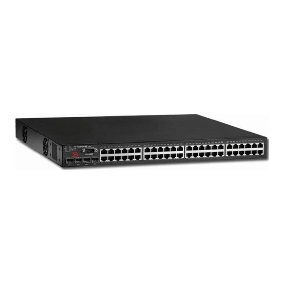
FWS624, FWS648, FWS624G, FWS648G rear panel 100 240 V~ 50 60 Hz, 2A ,10A FWS624-POE, FWS648-POE, FWS624G-POE, FWS648G-POE FastIron WS POE devices provide high 10/100 port density and Gigabit Ethernet uplinks in a compact form factor: • FastIron WS624-POE includes 20 x 10/100 Mbps PoE ports plus 4 Combo 10/100/1000 Mbps copper (RJ45 PoE) or 100/1000 Ethernet Fiber (SFP) ports. -
Page 13: Control Features
Hardware features FIGURE 4 FWS624-POE, FWS624G-POE FIGURE 5 FWS648-POE, FWS648G-POE FIGURE 6 FWS624-POE, FWS648-POE, FWS624G-POE, FWS648G-POE rear panel +12V , 10A 54V , 8.2A 100 240 V~ , 50 60 Hz , 10A Control features Serial management interface (console port) The serial management interface allows you to configure and manage the device using a third-party terminal emulation application on a directly connected PC. - Page 14 DRAFT: BROCADE CONFIDENTIAL Hardware features • 10/100/1000 RJ-45 or 100/1000 SFP (1-GE) combo ports (Ports 1~4) FWS624G and FWS648G devices provide the following interfaces: • 10/100/1000 Mbps ports with RJ-45 copper connectors (Ports 5~24 or Ports 5~48) • 10/100/1000 RJ-45 or 100/1000 SFP (1-GE) combo ports (Ports 1~4) FastIron WS 10/100/1000 BASE-T ports These devices contain 24/48 RJ-45 ports that operate at 10 Mbps or 100 Mbps, half or full duplex, or at 1000 Mbps, full duplex.
-
Page 15: Port And System Status Leds
DRAFT: BROCADE CONFIDENTIAL Hardware features SFP network interfaces Table 1 describes the network interfaces supported on the device. For network interface specifications, refer to the table “Cable length summary table” on page 50. TABLE 1 Supported SFP network interfaces for FWS devices Interface Show media description 1000Base-BX-D... -
Page 16: Power Supplies
DRAFT: BROCADE CONFIDENTIAL Hardware features FIGURE 8 System status LEDs 2 System status LEDs TABLE 3 System status LEDs Condition Status Power Green Internal power is operating normally. Amber Internal power supply fault. Power off or failure. Stack System stand alone Green System in stacking master mode Amber... - Page 17 DRAFT: BROCADE CONFIDENTIAL Hardware features FIGURE 9 Power supply receptacles 1 Power socket 2 Redundant power socket FIGURE 10 Power supply receptacles (POE Models) 1 Power socket 2 Redundant power socket Brocade FastIron WS Hardware Installation Guide 53-1002188-01...
- Page 18 DRAFT: BROCADE CONFIDENTIAL Hardware features Brocade FastIron WS Hardware Installation Guide 53-1002188-01...
-
Page 19: Installing Fws624 And Fws648 Models
• A straight-through EIA/TIA DB-9 serial cable (F or F). The serial cable can be ordered separately from Brocade Communications Systems Inc.. If you prefer to build your own cable, refer to the pinout information in “Attaching a PC or terminal”... -
Page 20: Installation Precautions
DRAFT: BROCADE CONFIDENTIAL Installation precautions TABLE 4 Summary of installation tasks Task Task Where to find more information number Ensure that the physical environment that will host the “Preparing the installation site” on page 12 device has the proper cabling and ventilation. Install any required optional modules into the device. -
Page 21: Lifting Precautions
DRAFT: BROCADE CONFIDENTIAL Installation precautions CAUTION Do not install the device in an environment where the operating ambient temperature might exceed 40 C (104 CAUTION Make sure the air flow around the front and sides of the device is not restricted. CAUTION Never leave tools inside the device. -
Page 22: Preparing The Installation Site
DRAFT: BROCADE CONFIDENTIAL Preparing the installation site CAUTION Ensure that the device does not overload the power circuits, wiring, and over-current protection. To determine the possibility of overloading the supply circuits, add the ampere (amp) ratings of all devices installed on the same circuit as the device. Compare this total with the rating limit for the circuit. -
Page 23: Installing The Device
DRAFT: BROCADE CONFIDENTIAL Preparing the installation site • Allow for the device to be connected to a separate grounded power outlet that provides 110 to 240 VAC, 50 to 60 Hz, is within 2 m (6.6 feet) of each device and is powered from an independent circuit breaker. -
Page 24: Rack Mount Installation
DRAFT: BROCADE CONFIDENTIAL Preparing the installation site 5. If you are also installing an redundant power supply, place it close to the device. Rack mount installation NOTE You need a #2 Phillips screwdriver for installation. Before mounting the device in a rack, consider the following factors: •... -
Page 25: Installing A Redundant Power Supply
DRAFT: BROCADE CONFIDENTIAL Installing a redundant power supply FIGURE 13 Installing the device in a rack 4. If you are installing a single device, proceed to “Activating power to the device” on page 26. 5. If you are installing multiple devices, mount them in the rack, one below the other, in any order. 6. - Page 26 DRAFT: BROCADE CONFIDENTIAL Installing a redundant power supply • Thermal overload protection prevents the redundant power supply from overheating if a thermal overload occurs. • Over-voltage protection shuts down an output channel if voltage exceeds a preset threshold. • Over-current protection shuts down the power supply if output load exceeds a preset threshold. •...
-
Page 27: Rps12 External Redundant Power Supply
DRAFT: BROCADE CONFIDENTIAL Installing a redundant power supply FIGURE 15 RPS2-EIF LEDs Port indicators System indicators TABLE 5 Port status LEDs - RPS2-EIF LED (1~4) Condition Status Link The port does not have a valid connection to a device. On Yellow The port has a valid connection to a device. - Page 28 • FastIron WS FWS648-POE • FastIron WS FWS624G-POE • FastIron WS FWS648G-POE Features and benefits • Supports up to four connections to FastIron WS PoE devices • Can supply one out of four connected device with 12V DC primary power and -54V DC PoE power •...
- Page 29 DRAFT: BROCADE CONFIDENTIAL Installing a redundant power supply Power socket Redundant power sockets 4-3 Redundant power sockets 2-1 Power system status indicator Package contents • Redundant power supply (RPS12) • One AC supply power cord — US, Continental Europe or UK •...
-
Page 30: Selecting A Redundant Power Supply Installation Site
DRAFT: BROCADE CONFIDENTIAL Installing a redundant power supply TABLE 8 System Status LEDs - RPS12 Condition Status Power On Green AC power is being supplied to the power supply. No AC power is being supplied to the power supply. Status On Green The power supply is operating normally. -
Page 31: Equipment Checklist
DRAFT: BROCADE CONFIDENTIAL Installing a redundant power supply Equipment checklist When you unpack the RPS2-EIF or RPS12 power supply, make sure you have received all the components. (Refer to “Package contents” on page 16.) Before beginning the installation, be sure you have all other necessary installation equipment. -
Page 32: Desktop Or Shelf Mounting
DRAFT: BROCADE CONFIDENTIAL Installing a redundant power supply FIGURE 19 Installing the redundant power supply in a rack L in k A c t iv it y F a n T h e rm a l P o w e r 3. -
Page 33: Connecting Devices To The Redundant Power Supply
DRAFT: BROCADE CONFIDENTIAL Installing a redundant power supply Connecting devices to the redundant power supply The FastIron RPS2-EIF is supported on the following devices: • FastIron WS624 • FastIron WS648 The FastIron RPS12 is supported on the following devices: • FastIron FWS624-POE •... -
Page 34: Port Pin-Out Diagram For The Rps2-Eif Power Supply
DRAFT: BROCADE CONFIDENTIAL Installing a redundant power supply FIGURE 22 Connecting multiple devices to a redundant power supply. 1 Input port FWS devices 2 AC power supply no.1 Output port 3 Redundant power supply AC power supply no.2 NOTE For International use, you may need to change the AC line cord. You must use a line cord set that has been approved for the receptacle type in your country. -
Page 35: Port Pin-Out Diagram For The Rps12 Power Supply
DRAFT: BROCADE CONFIDENTIAL Installing a redundant power supply FIGURE 23 RPS2-EIF power supply port pinout diagram N.C. N.C. 12 V RPS Present 12 V Status 1 12 V Status 2 12 V Power Good TABLE 9 Port pin-out diagram for the RPS2-EIF power supply Name Description 1, 7, 8, 14... -
Page 36: Activating Power To The Device
DRAFT: BROCADE CONFIDENTIAL Activating power to the device FIGURE 24 Pin-out diagram for the RPS12 power supply. -54 V -54 V RTN -54 V -54 V RTN -54 V RTN -54 V N. C. N. C. N. C. RPS Present N. -
Page 37: Verifying Proper Operation
DRAFT: BROCADE CONFIDENTIAL Verifying proper operation 1. Remove the power cord from the shipping package. 2. Attach the AC power cable to the AC connector on the rear panel. 3. Insert the power cable plug into a 115V/120V outlet. NOTE To turn the system off, simply unplug the power cord or cords. - Page 38 DRAFT: BROCADE CONFIDENTIAL Attaching a PC or terminal 1. Connect a PC or terminal to the serial port using a straight-through cable. The serial port has a male DB-9 connector. NOTE You will need to run a terminal emulation program on the PC. 2.
-
Page 39: Connecting Network Devices And Checking Connectivity
DRAFT: BROCADE CONFIDENTIAL Chapter Connecting Network Devices and Checking Connectivity Assigning permanent passwords This chapter provides the details for connecting network devices. DANGER The procedures in this manual are for qualified service personnel. By default, the CLI is not protected by passwords. To secure CLI access, Brocade strongly recommends assigning passwords. -
Page 40: Recovering From A Lost Password
DRAFT: BROCADE CONFIDENTIAL Configuring IP addresses 2. Access the CONFIG level of the CLI by entering the following command. FWSSwitch# configure terminal FWSSwitch(config)# 3. Enter the following command to set the super-user password. FWSSwitch(config)# enable super-user-password <text> NOTE You must set the super-user password before you can set other types of passwords. 4. -
Page 41: Devices Running Layer 2 Software
DRAFT: BROCADE CONFIDENTIAL Configuring IP addresses • To enter a classical network mask, enter the mask in IP address format. For example, enter “209.157.22.99 255.255.255.0” for an IP address with a Class-C subnet mask. • To enter a prefix number for a network mask, enter a forward slash ( / ) and the number of bits in the mask immediately after the IP address. -
Page 42: Devices Running Layer 3 Software
DRAFT: BROCADE CONFIDENTIAL Configuring IP addresses Devices running layer 3 software NOTE Devices require a software license to be able to run Edge Layer 3 features. For details, see the FastIron Configuration Guide. Configuring IP addresses You can configure an IP address on the following types of Layer 3 switch interfaces: •... - Page 43 DRAFT: BROCADE CONFIDENTIAL Configuring IP addresses Assigning an IP address to a loopback interface Loopback interfaces are always up, regardless of the states of physical interfaces. You can configure up to eight loopback interfaces. You can add up to 24 IP addresses to each loopback interface. To add a loopback interface, enter commands such as those shown in the following example.
-
Page 44: Connecting Network Devices
DRAFT: BROCADE CONFIDENTIAL Configuring IP addresses This command deletes IP address 1.1.2.1. You do not need to enter the subnet mask. To delete all IP addresses from an interface, enter the following command. FWSSwitch(config-if-0/1/1)# no ip address * Syntax: no ip address <ip-addr> | * Connecting network devices Brocade devices support connections to other vendors’... -
Page 45: Connecting To Workstations, Servers, Or Routers
DRAFT: BROCADE CONFIDENTIAL Configuring IP addresses FIGURE 27 Straight-through cable EIA/TIA 568B RJ-45 Wiring Standard 10/100BASE-TX Straight-through Cable White/Orange Stripe Orange White/Green Stripe End A End B Blue White/Blue Stripe Green White/Brown Stripe Brown Connecting to workstations, servers, or routers Straight-through UTP cabling is required for direct UTP attachment to workstations, servers, or routers using network interface cards (NICs). - Page 46 DRAFT: BROCADE CONFIDENTIAL Configuring IP addresses You can install a new fiber optic module in an SFP slot while the FastIron WS CHE1 is powered on and running. Before installing one of these modules into the slot, have the following on hand. NOTE An ESD wrist strap with a plug for connection to a metal surface.
-
Page 47: Testing Connectivity
DRAFT: BROCADE CONFIDENTIAL Testing connectivity Cleaning the fiber-optic connectors To avoid problems with the connection between the fiber optic module (SFP (mini-GBIC)) and the fiber cable connectors, Brocade strongly recommends cleaning both connectors each time you disconnect and reconnect them. In particular, dust can accumulate in the connectors and cause problems such as reducing the optic launch power. -
Page 48: Tracing A Route
DRAFT: BROCADE CONFIDENTIAL Testing connectivity TABLE 12 Network connection-related LED states Desired state Meaning Abnormal state Meaning or action Link (1-24/48) On (Green) A link is established with A link is not established with the remote port. You can do the remote port. -
Page 49: Troubleshooting Network Connections
DRAFT: BROCADE CONFIDENTIAL Troubleshooting network connections Troubleshooting network connections Follow these guidelines when troubleshooting your network connections: • For the indicated port, verify that both ends of the cabling (at the Brocade device and the connected device) are snug. • Verify that the Brocade device and the connected device are both powered on and operating correctly. -
Page 50: Digital Optical Monitoring
DRAFT: BROCADE CONFIDENTIAL Troubleshooting network connections Viewing the results of the cable analysis To display the results of the cable analysis, enter a command such as the following at the Privileged EXEC level of the CLI. FWSSwitch#show cable-diag tdr 0/1/1 Port Speed Local pair Pair Length Remote pair Pair status --------- ----- ---------- ----------- ----------- -----------... -
Page 51: Managing The Fastiron Ws Hardware
DRAFT: BROCADE CONFIDENTIAL Chapter Managing the FastIron WS Hardware Managing FastIron WS temperature settings This chapter provides instructions for managing the device. DANGER The procedures in this manual are for qualified service personnel. This section describes how to display temperature settings on the device and how to change the temperature warning and shutdown levels. - Page 52 DRAFT: BROCADE CONFIDENTIAL Managing FastIron WS temperature settings FastIron# show chassis chassis Power supply/fan/temperature FastIron# show chassis Power supply 1 (NA - AC - Regular) present, status ok Power supply 2 not present Fan 1 ok, speed (auto): [[1]]<->2<->3 Fan 2 ok, speed (auto): [[1]]<->2<->3 Fan controlled temperature: 50.5 deg-C Fan speed switching temperature thresholds: Speed 1: NM<----->53...
- Page 53 DRAFT: BROCADE CONFIDENTIAL Managing FastIron WS temperature settings To display the system log, enter the following command at any CLI level. FWS 624 Router#show log Syslog logging: enabled (0 messages dropped, 0 flushes, 0 overruns) Buffer logging: level ACDMEINW, 8 messages logged level code: A=alert C=critical D=debugging M=emergency E=error I=informational N=notification W=warning Static Log Buffer:...
-
Page 54: Removing Mac Address Entries
DRAFT: BROCADE CONFIDENTIAL Managing FastIron WS temperature settings To change the temperature at which the device sends a warning, enter a command such as the following at the Privileged EXEC level of the CLI. FWS 624 Router#temperature warning 47 Syntax: temperature warning <value> The <value>... -
Page 55: Displaying Cpu Usage
DRAFT: BROCADE CONFIDENTIAL Displaying CPU usage Displaying CPU usage You can display the amount of the CHE1 CPU in use. To do so, enter the following command at any level of the CLI. FWS 624 Router#show cpu 31 percent busy, from 3248 sec ago sec avg: 10 percent busy sec avg:... -
Page 56: Installing A New Fiber Optic Module
DRAFT: BROCADE CONFIDENTIAL Cabling a fiber optic module Remove a fiber optic module from an SFP slot. 1. Put on the ESD wrist strap and ground yourself by attaching the clip end to a metal surface (such as an equipment rack). 2. -
Page 57: Chapter 5 Hardware Specifications
DRAFT: BROCADE CONFIDENTIAL Chapter Hardware Specifications Hardware specifications for FastIron WS models This chapter contains hardware specifications for the Brocade Communications Systems Inc. FastIron WS. Physical dimensions and weight Table 14 lists the physical dimensions and weight for the FastIron WS family of switches. -
Page 58: Cooling System And Fans
DRAFT: BROCADE CONFIDENTIAL Hardware specifications for FastIron WS models TABLE 18 Operating environment Operating temperature Relative humidity Operating altitude – 40 C (32 – 104 C (5 to 95%, @ 104.9 F), non-condensing 0 – 2000 meters (0 – 6,600 ft ) •... -
Page 59: Pinouts And Signalling
DRAFT: BROCADE CONFIDENTIAL Hardware specifications for FastIron WS models Pinouts and signalling This section lists the pinouts for the DB-9 connector and RJ-45 port jacks. Serial (console) port pinouts The Console port is a standard male DB-9 connector, as shown in the following figure Most PC serial ports require a cable with a female DB-9 connector. -
Page 60: Cable Specifications
DRAFT: BROCADE CONFIDENTIAL Hardware specifications for FastIron WS models FIGURE 31 Pin assignment and signalling for 10/100BaseTX and 1000BaseT ports 100BaseTX and 1000BaseT 10BaseT Pin Assignment Pin Number MDI-X ports Pin Number MDI-X ports Not used Not used Not used Not used Cable specifications Table 20... -
Page 61: Power Cords
DRAFT: BROCADE CONFIDENTIAL Hardware specifications for FastIron WS models TABLE 20 Cable length summary table (Continued) Cable type Connector type Core diameter Modal bandwidth Range (meters) (microns) (MHz*km) or wavelength (nm) 1000Base-SX LC connector for SFP 62.5/125 .5 – 275 module 62.5/125 .5 –... -
Page 62: Power Specifications For Poe
Hardware specifications for FastIron WS models Specifications TABLE 21 Specifications for AC power Property FWS624, FWS624G FWS648, FWS648G FWS624-PoE, FWS648-PoE, FWS648G-PoE FWS624G-PoE Input voltage range 100 – 240 VAC 100 – 240 VAC 100 – 240 VAC 100 – 240 VAC Input current <... -
Page 63: Chapter 6 Troubleshooting
DRAFT: BROCADE CONFIDENTIAL Chapter Troubleshooting Diagnosing switch indicators TABLE 22 Troubleshooting chart Symptom Action • Power LED is Off Internal power supply is disconnected. • Check connections between the switch, the power cord, and the wall outlet. • Contact Technical Support. •... -
Page 64: In-Band Access
DRAFT: BROCADE CONFIDENTIAL Diagnosing switch indicators In-band access You can access the management agent in the switch from anywhere within the attached network using Telnet, a Web browser, or other network management software. However, you must first configure the switch with a valid IP address, subnet mask, and default gateway. If you have trouble establishing a link to the management agent, check to see if you have a valid network connection. -
Page 65: Regulatory Statements
DRAFT: BROCADE CONFIDENTIAL Appendix Regulatory Statements USA (FCC CFR 47 part 15 warning) This equipment has been tested and found to comply with the limits for a Class A digital device pursuant to Part 15 of the FCC Rules. These limits are designed to provide reasonable protection against harmful interference when the equipment is operated in a commercial environment. -
Page 66: Japan Power Cord
DRAFT: BROCADE CONFIDENTIAL Japan power cord English translation of above statement This is Class A product based on the standard of the Voluntary Control Council For Interference by Information Technology Equipment (VCCI). If this equipment is used in a domestic environment, radio disturbance may arise. -
Page 67: Regulatory Compliance
DRAFT: BROCADE CONFIDENTIAL Regulatory compliance Regulatory compliance Table 23 lists the Electromagnetic Compatibility (EMC), Immunity standards, and safety agency approvals for the FastIron family of switches. TABLE 23 Regulatory compliance and safety approvals Certifications Emissions: • ICES-003, Electromagnetic Emission • FCC Part 15 Class A •... - Page 68 DRAFT: BROCADE CONFIDENTIAL Regulatory compliance Brocade FastIron WS Hardware Installation Guide 53-1002188-01...
-
Page 69: Caution And Danger Notices
DRAFT: BROCADE CONFIDENTIAL Appendix Caution and Danger Notices The caution and danger notices that appear in this manual are listed below in English, German, French, and Spanish. Cautions A caution calls your attention to a possible hazard that can damage equipment. “Vorsicht”... - Page 70 DRAFT: BROCADE CONFIDENTIAL Cautions CAUTION Ensure that the device does not overload the power circuits, wiring, and over-current protection. To determine the possibility of overloading the supply circuits, add the ampere (amp) ratings of all devices installed on the same circuit as the device. Compare this total with the rating limit for the circuit.
-
Page 71: Danger
DRAFT: BROCADE CONFIDENTIAL Danger CAUTION Changes or modifications made to this device that are not expressly approved by the party responsible for compliance could void the user's authority to operate the equipment. VORSICHT Falls dieses Gerät verändert oder modifiziert wird, ohne die ausdrückliche Genehmigung der für die Einhaltung der Anforderungen verantwortlichen Partei einzuholen, kann dem Benutzer der weitere Betrieb des Gerätes untersagt werden. - Page 72 DRAFT: BROCADE CONFIDENTIAL Danger DANGER The procedures in this manual are for qualified service personnel. GEFAHR Die Verfahren in diesem Handbuch sind nur für qualifiziertes Wartungspersonal gedacht. DANGER Les procédures décrites dans ce manuel doivent être effectuées par le personnel de service qualifié...
- Page 73 DRAFT: BROCADE CONFIDENTIAL Danger DANGER Disconnect the power cord from all power sources to completely remove power from the device. GEFAHR Ziehen Sie das Stromkabel aus allen Stromquellen, um sicherzustellen, dass dem Gerät kein Strom zugeführt wird. DANGER Débranchez le cordon d'alimentation de toutes les sources d'alimentation pour couper complètement l'alimentation du dispositif.
- Page 74 DRAFT: BROCADE CONFIDENTIAL Danger Brocade FastIron WS Hardware Installation Guide 53-1002188-01...
Need help?
Do you have a question about the FWS648G-POE and is the answer not in the manual?
Questions and answers