
Subscribe to Our Youtube Channel
Related Manuals for Brocade Communications Systems FastIron GS


Summary of Contents for Brocade Communications Systems FastIron GS
- Page 1 DRAFT: BROCADE CONFIDENTIAL 53-1001783-01 ® 05 February 10 Brocade FastIron GS and GS-STK Hardware Installation Guide Supporting Release 07.0.01...
- Page 2 NetIron, SecureIron, ServerIron, StorageX, and TurboIron are registered trademarks, and DCFM, Extraordinary Net- works, and SAN Health are trademarks of Brocade Communications Systems, Inc., in the United States and/or in other countries. All other brands, products, or service names are or may be trademarks or service marks of, and are used to identify, products or services of their respective owners.
-
Page 3: Table Of Contents
Installation location ........23 Brocade FastIron GS and FastIron GS-STK Hardware Installation Guide... - Page 4 Rack mount installation ....... 30 Installing FastIron GS-STK stackable devices ....33 Powering on the system .
- Page 5 Hardware maintenance schedule ......87 Brocade FastIron GS and FastIron GS-STK Hardware Installation Guide...
- Page 6 Warnings ..........107 Brocade FastIron GS and FastIron GS-STK Hardware Installation Guide...
-
Page 7: About This Document
For readability, command names in the narrative portions of this guide are presented in mixed lettercase: for example, switchShow. In actual examples, command lettercase is often all lowercase. Otherwise, this manual specifically notes those cases in which a command is case sensitive. Brocade FastIron GS and FastIron GS-STK Hardware Installation Guide 53-1001783-01... -
Page 8: Command Syntax Conventions
This document may contain references to the trademarks of the following corporations. These trademarks are the properties of their respective companies and corporations. These references are made for informational purposes only. Corporation Referenced Trademarks and Products Royal Phillips Electronics Inc. Phillips viii Brocade FastIron GS and FastIron GS-STK Hardware Installation Guide 53-1001783-01... -
Page 9: Related Publications
FastIron Configuration Guide – for FastIron Edge Switch X Series (FESX), FastIron SuperX Switch (FSX), FastIron SX 800, FastIron SX 1600, FastIron Workgroup Switch X Series (FWSX), FastIron GS (FGS), FastIron GS-STK, FastIron LS, FastIron LS-STK, and FastIron WS products. Provides configuration procedures for system-level features, Layer 2 features, and... - Page 10 DRAFT: BROCADE CONFIDENTIAL Brocade FastIron GS and FastIron GS-STK Hardware Installation Guide 53-1001783-01...
-
Page 11: Product Overview
DRAFT: BROCADE CONFIDENTIAL Chapter Product Overview Product overview This chapter contains an overview of the following Brocade FastIron GS (FGS) and FastIron GS-STK (FGS-STK) products: TABLE 1 FastIron GS and GS-STK Models Standard Models Stackable Models FGS624P FGS624P-STK 24 port device, POE and stacking upgradeable... -
Page 12: Poe Applications
Because POE can provide power over Ethernet cable, power is continuous, even in the event of a power failure. Brocade FastIron GS and FastIron GS-STK Hardware Installation Guide 53-1001783-01... -
Page 13: Hardware Features
You can use a combination of fiber and copper ports, or all four copper, or all four fiber ports, as needed. For more information, refer to “Combination ports” on page 9. • Two 10 Gbps ports (optional). Refer to “10 Gbps ports” on page 9. Brocade FastIron GS and FastIron GS-STK Hardware Installation Guide 53-1001783-01... -
Page 14: Fgs624Xgp And Fgs624Xgp-Poe Devices
A single POE daughter card supports 24 POE ports. Two POE daughter cards support 48 POE ports. FGS648P-POE devices ship with the POE daughter cards installed. Figure 3 shows the FGS648P and FGS648P-POE devices. Brocade FastIron GS and FastIron GS-STK Hardware Installation Guide 53-1001783-01... -
Page 15: Control Features
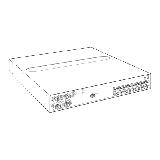
• Optionally, two10 Gigabit Ethernet ports for XFP MSA-compliant fiber connectors • LEDs for ports, power supplies, and stacking The following illustrations show the front panels of the FGS models. Brocade FastIron GS and FastIron GS-STK Hardware Installation Guide 53-1001783-01... - Page 16 5 6 7 8 PS1 PS2 Pwr FGS-2XGC Gigabit fiber ports 1-4 2-port 10 Gbps Ethernet CX4 module, ports 25 and 26 10 Gigabit Ethernet XFP Gigabit Ethernet copper ports 1-24 Brocade FastIron GS and FastIron GS-STK Hardware Installation Guide 53-1001783-01...
- Page 17 The reset button allows you to restart the system without switching the power supplies off and on, or using the CLI or Web management interface. The button is located to the right of the console port and is recessed to prevent it from being pushed accidentally. Brocade FastIron GS and FastIron GS-STK Hardware Installation Guide 53-1001783-01...
-
Page 18: Network Interfaces
10/100/1000 copper ports use auto-sensing and auto-negotiating to determine the speed (10 Mbps, 100 Mbps, or 1000 Mbps) and mode (full-duplex or half-duplex) of the port at the other end of the link, and adjust port speed accordingly. Brocade FastIron GS and FastIron GS-STK Hardware Installation Guide 53-1001783-01... - Page 19 2-port 10-Gigabit module installed at the factory, or you can upgrade your device at a later time. Figure 10 shows the 2-port 10 Gbps module. This module supports the 10 Gbps connector types (10GBase) listed in Table Brocade FastIron GS and FastIron GS-STK Hardware Installation Guide 53-1001783-01...
- Page 20 FIGURE 12 2-port Hybrid 10GbE and CX4 Module When this module is installed, the show media command returns the following display: FGS648 Switch# show media 0/2/1:<depends on transceiver installed> 0/2/2:CX4 Brocade FastIron GS and FastIron GS-STK Hardware Installation Guide 53-1001783-01...
- Page 21 The CX4 transceiver requires a 15 meter CX4-grade cable, which may be purchased from Brocade. Refer to part number CAB-CX4-0050 when ordering. Figure 13 shows the CX4 transceiver. Figure 14 shows the CX4-grade cable. FIGURE 13 CX4 Transceiver Brocade FastIron GS and FastIron GS-STK Hardware Installation Guide 53-1001783-01...
- Page 22 The link is down. Left for upper copper connector Right for lower copper connector Blinking The port is transmitting or receiving traffic 100/1000 Fiber Port LEDs Brocade FastIron GS and FastIron GS-STK Hardware Installation Guide 53-1001783-01...
- Page 23 Specifications”lists the types of fiber optic modules (SFPs and XFPs) supported on Brocade FGS and FGS-STK devices. Table 3 describes the output of the show media command for each media type. Brocade FastIron GS and FastIron GS-STK Hardware Installation Guide 53-1001783-01...
-
Page 24: Power Supplies
(if applicable) or for additional POE power. You can use any combination of AC and DC supplies in the same device. Figure 15 shows the front panel of the AC power supply used with FastIron GS and GS-STK devices. FIGURE 15 RPS-FGS AC power supply front panel Figure 16 shows the front panel of the DC power supply used with FastIron GS and GS-STK devices. - Page 25 You can install a second 48-volt supply for additional POE power. NOTE If your FastIron GS or GS-STK POE device has 48 ports and only one power supply, and each POE-enabled port needs 15.4 watts, then a maximum of 31 ports can supply power to connected devices.
-
Page 26: Cooling System And Fans
FGS and FGS-STK devices have two single-speed fans that operate simultaneously. If one fan fails, it does not affect the operation of the other fan. For more information about fans and the cooling system, refer to “Cooling” on page 70. Brocade FastIron GS and FastIron GS-STK Hardware Installation Guide 53-1001783-01... -
Page 27: Installing Fastiron Gs And Fastiron Gs-Stk Devices
“Connecting Network Devices and Checking Connectivity” on page 55. FastIron GS and FastIron GS-STK devices ship with all of the items listed below. Please review the list and verify the contents of your shipping container. If any items are missing, please contact the place of purchase. -
Page 28: Summary Of Installation Tasks
Foundry IronView Network Management User’s also can use IronView Network Manager to manage the device. Guide Secure access to the device. FastIron Configuration Guide Installation precautions Follow these precautions when installing a Brocade device. Brocade FastIron GS and FastIron GS-STK Hardware Installation Guide 53-1001783-01... -
Page 29: General Precautions
Mount the devices you install in a rack or cabinet as low as possible. Place the heaviest device at the bottom and progressively place lighter devices above. Power precautions The following precautions apply to FastIron GS POE and FastIron GS-STK POE 48-port devices: Brocade FastIron GS and FastIron GS-STK Hardware Installation Guide 53-1001783-01... - Page 30 DRAFT: BROCADE CONFIDENTIAL Installation precautions • If your FastIron GS or GS-STK POE device has 48 ports and only one power supply, and each POE-enabled port needs 15.4 watts, then a maximum of 31 ports can supply power to connected devices.
- Page 31 CAUTION: The FGS power supply is designed exclusively for use with the FGS devices. The power supply produces extensive power to support 802.3af applications. Installing the power supply in a device other than the FGS will cause extensive damage to your equipment. Brocade FastIron GS and FastIron GS-STK Hardware Installation Guide 53-1001783-01...
- Page 32 The mark is your assurance that the power cord can be used safely with the device. Brocade FastIron GS and FastIron GS-STK Hardware Installation Guide 53-1001783-01...
-
Page 33: Preparing The Installation Site
Otherwise, the power supply or the device could be damaged. The device can be running while a power supply is being installed or removed, but the power supply itself should be disconnected from the power source. Brocade FastIron GS and FastIron GS-STK Hardware Installation Guide 53-1001783-01... -
Page 34: Installing An Ac Power Supply
“Power precautions” on page 19. Use the following procedures to install AC power supplies in FastIron GS and GS-STK devices. You will need a #2 Phillips-head screwdriver to perform these procedures. To install an AC power supply, do the following: 1. - Page 35 Install the power cord, and secure it wIth the retaining bale, as shown in Figure NOTE The edges of the power supply panels will extend approximately .25 in.beyond the side of the device. Brocade FastIron GS and FastIron GS-STK Hardware Installation Guide 53-1001783-01...
-
Page 36: Installing A Dc Power Supply
Installing the AC Power Cord Retaining bale AC power cord Installing a DC power supply Use the following procedures to install DC power supplies in a FastIron GS or FastIron GS-STK device. Figure 21 shows the front panel of a DC power supply. - Page 37 The power supply is right-side up when the power connector is on the left and the fan vent is on the right. Brocade FastIron GS and FastIron GS-STK Hardware Installation Guide 53-1001783-01...
- Page 38 Press the two latches on the supply outward to lock the supply in place. 8. If you removed the receptacle for the positive and negative terminals, re-position it and secure the screws. Brocade FastIron GS and FastIron GS-STK Hardware Installation Guide 53-1001783-01...
- Page 39 Connect the 48 RTN lead to the positive (+) terminal and tighten the positive terminal screw. • Figure 26 shows how to connect the wires on a DC power supply. Brocade FastIron GS and FastIron GS-STK Hardware Installation Guide 53-1001783-01...
-
Page 40: Installing The Device
– a 3-in. clearance is recommended on each side. 2. Proceed to “Powering on the system” on page 35. Rack mount installation For rack mount installation, Brocade recommends that you use a Telco equipment rack. Brocade FastIron GS and FastIron GS-STK Hardware Installation Guide 53-1001783-01... - Page 41 • Figure 27 shows how to attach the short mounting brackets. • Figure 28 shows how to attach the long mounting brackets. FIGURE 27 Attaching the Short Mounting Brackets Brocade FastIron GS and FastIron GS-STK Hardware Installation Guide 53-1001783-01...
- Page 42 .25 inches, making it impossible to insert into a standard Telco rack with both power supplies installed. 4. Proceed to “Powering on the system” on page 35. Brocade FastIron GS and FastIron GS-STK Hardware Installation Guide 53-1001783-01...
-
Page 43: Installing Fastiron Gs-Stk Stackable Devices
2 - 82 50/125um MMF 2000 2 - 300 >400 Average distance range is between 2 - 33 meters. Brocade recommends using the 2000 bandwidth version for distances greater than 80 meters. Brocade FastIron GS and FastIron GS-STK Hardware Installation Guide 53-1001783-01... - Page 44 5 6 7 8 PS1 PS2 Pwr FGS-2XG Stack Lnk-Act Console Even 5 6 7 8 PS1 PS2 Pwr Stack Lnk-Act Console Even 5 6 7 8 PS1 PS2 Pwr Brocade FastIron GS and FastIron GS-STK Hardware Installation Guide 53-1001783-01...
-
Page 45: Powering On The System
Remove the power cord from the shipping package. • Attach the AC power cable to the AC connector on the rear panel and secure with retaining bale, as shown in Figure Brocade FastIron GS and FastIron GS-STK Hardware Installation Guide 53-1001783-01... -
Page 46: Powering Off The System
If the links on these cables are good and the connected device is powered on, the link LEDs will light. • Table 7 provides more details on specific LED conditions after system start-up. Brocade FastIron GS and FastIron GS-STK Hardware Installation Guide 53-1001783-01... -
Page 47: Observing The Power Status Leds
2. Open the terminal emulation program and set the session parameters as follows: • Baud: 9600 bps • Data bits: 8 • Parity: None • Stop bits: 1 • Flow control: None Brocade FastIron GS and FastIron GS-STK Hardware Installation Guide 53-1001783-01... - Page 48 Figure 33 Figure 34, some of the wires should not be connected. If you do connect the wires that are labeled “Reserved”, you might get unexpected results with some terminals. Brocade FastIron GS and FastIron GS-STK Hardware Installation Guide 53-1001783-01...
- Page 49 Serial Port Pin Assignments Showing Cable Connection Options to a Terminal or PC DB-9 to DB-9 DB-9 to DB-25 Female Switch Terminal or PC Female Switch Terminal or PC Reserved Reserved Reserved Reserved Reserved Reserved Reserved Reserved Brocade FastIron GS and FastIron GS-STK Hardware Installation Guide 53-1001783-01...
- Page 50 DRAFT: BROCADE CONFIDENTIAL Attaching a PC or terminal Brocade FastIron GS and FastIron GS-STK Hardware Installation Guide 53-1001783-01...
-
Page 51: Chapter 3 Eprem Upgrade For Fastiron Gs Devices
Chapter EPREM Upgrade for FastIron GS Devices These installation instructions describe how to upgrade your standalone FastIron GS device to support Edge Layer 3 features (software release FGS 07.0.01 and later). If you have any questions about performing this upgrade, please contact your place of purchase or Brocade at 1.877.TURBOCALL (887.2622) inside the United States or 408.207.1600 outside the... -
Page 52: Remove The Cover From The Device
Removing cover screws on an FGS device. Sl ot 3 5. Remove the cover by sliding it to the rear of the device and then lifting it off, as shown in Figure Brocade FastIron GS and FastIron GS-STK Hardware Installation Guide 53-1001783-01... - Page 53 Straighten any crooked pins, then try again. FIGURE 37 EEPROM socket and memory DIMM locations on FGS 624 and 648 devices Brocade FastIron GS and FastIron GS-STK Hardware Installation Guide 53-1001783-01...
- Page 54 6. Re-insert any power cables and power on the device. Your EPREM upgrade is now complete. Refer to the FastIron Configuration Guide for information about the Edge Layer 3 features available with release 07.0.01. Brocade FastIron GS and FastIron GS-STK Hardware Installation Guide 53-1001783-01...
-
Page 55: Upgrading Software
5. Reload the switch by entering one of the following commands: • reload (this command boots from the default boot source, which is the primary flash area by default) boot system flash primary | secondary Brocade FastIron GS and FastIron GS-STK Hardware Installation Guide 53-1001783-01... - Page 56 DRAFT: BROCADE CONFIDENTIAL Upgrading software Brocade FastIron GS and FastIron GS-STK Hardware Installation Guide 53-1001783-01...
-
Page 57: Stacking Upgrade For The Fastiron Gs
Stacking Upgrade for the FastIron GS This chapter describes how to upgrade your FastIron GS device to support the stacking features introduced in IronWare software release 07.0.01. To upgrade your device, you will need to replace the current 128 MB memory with 256 MB memory, and install the stacking EEPROM. -
Page 58: Upgrading Hardware
Turn the device so that the front (where the port connectors are) is facing you. • Slide the cover backwards to free the lip edge of the cover from the front plate. Make sure the cover is completely free of the front panel. Brocade FastIron GS and FastIron GS-STK Hardware Installation Guide 53-1001783-01... - Page 59 Make sure you insert the EEPROM so that pin 1 goes into the correct hole as shown in the illustrations. If you accidentally insert the EEPROM backwards, the device will not work and may be damaged when you power it on. Brocade FastIron GS and FastIron GS-STK Hardware Installation Guide 53-1001783-01...
- Page 60 Lift the old DIMM up and pull it out of the holder. CAUTION Memory DIMMs are not interchangeable between FGS and FLS devices. Make sure you are installing the correct DIMM for your device (refer to Figure 41). Brocade FastIron GS and FastIron GS-STK Hardware Installation Guide 53-1001783-01...
- Page 61 13. If you are not installing a CX4 module, proceed to step 12. Remove the cover plate from the module slot on the front panel, as shown in Figure Brocade FastIron GS and FastIron GS-STK Hardware Installation Guide 53-1001783-01...
- Page 62 • Re-insert the cover screws. 15. If applicable, re-attach the rack mounting ears. 16. Reinstall the device in an equipment rack, if necessary. 17. Reconnect power cables to the device. Brocade FastIron GS and FastIron GS-STK Hardware Installation Guide 53-1001783-01...
-
Page 63: Upgrading Software
CLI: show flash 4. If the flash code version is correct, go to step 5. Otherwise, go to step 5. Reload the software by entering one of the following commands: Brocade FastIron GS and FastIron GS-STK Hardware Installation Guide 53-1001783-01... - Page 64 DRAFT: BROCADE CONFIDENTIAL Upgrading Software • reload (this command boots from the default boot source, which is the primary flash area by default) • boot system flash primary | secondary Brocade FastIron GS and FastIron GS-STK Hardware Installation Guide 53-1001783-01...
-
Page 65: Connecting Network Devices And Checking Connectivity
CONFIG – This level lets you configure the system IP address, and switching and routing features. To access the CONFIG mode, you must already be logged into the Privileged level of the EXEC mode (the Enable level). Brocade FastIron GS and FastIron GS-STK Hardware Installation Guide 53-1001783-01... -
Page 66: Assigning A Password To An Ironstack
By default, the CLI does not require passwords. However, if someone has configured a password for the device but the password has been lost, you can regain super-user access to the device using the following procedure. Brocade FastIron GS and FastIron GS-STK Hardware Installation Guide 53-1001783-01... -
Page 67: Configuring Ip Addresses
Brocade devices support both classical IP network masks (Class A, B, and C subnet masks, and so on) and Classless Interdomain Routing (CIDR) network prefix masks. Brocade FastIron GS and FastIron GS-STK Hardware Installation Guide 53-1001783-01... - Page 68 Use the secondary parameter if you have already configured an IP address within the same subnet on the interface. NOTE When you configure more than one address in the same subnet, all but the first address are secondary addresses and do not form OSPF adjacencies. Brocade FastIron GS and FastIron GS-STK Hardware Installation Guide 53-1001783-01...
- Page 69 1 as the routing interface for the VLAN. The last two commands change to the interface configuration level for the virtual interface and assign an IP address to the interface. Brocade FastIron GS and FastIron GS-STK Hardware Installation Guide 53-1001783-01...
-
Page 70: Devices Running Layer 2 Software
FastIron(config)# ip default-gateway 192.22.3.1 NOTE You do not need to assign a default gateway address for single subnet networks. Syntax: enable [<password>] Syntax: configure terminal Syntax: [no] ip address <ip-addr> <ip-mask> Brocade FastIron GS and FastIron GS-STK Hardware Installation Guide 53-1001783-01... -
Page 71: Devices Running Stacking Software
1000Base-T ports. Therefore, a crossover cable may not be required; a straight-through cable may work as well. For more information about this feature, refer to the FastIron Configuration Guide. Brocade FastIron GS and FastIron GS-STK Hardware Installation Guide 53-1001783-01... -
Page 72: Connecting To Workstations, Servers, Or Routers
Fiber cabling is required for direct attachment to Gigabit NICs or switches and routers through fiber ports. Refer to “Connecting a network device to a fiber port” on page 63. Brocade FastIron GS and FastIron GS-STK Hardware Installation Guide 53-1001783-01... -
Page 73: Connecting A Network Device To A Fiber Port
3. Gently insert the fiber optic module into the port until the module clicks into place. The module is keyed to prevent incorrect insertion. Cabling a fiber optic module To cable a fiber optic module: Brocade FastIron GS and FastIron GS-STK Hardware Installation Guide 53-1001783-01... -
Page 74: Using A Cx4 Transceiver
For a link to operate properly, both sides must use identical CX4 transceivers. The CX4 transceiver requires a 15 meter CX4-grade cable, which may be purchased from Brocade. Refer to part number CAB-CX4-0050 when ordering. NOTE The CX4 transceiver is not hot-swappable. Brocade FastIron GS and FastIron GS-STK Hardware Installation Guide 53-1001783-01... -
Page 75: Testing Connectivity
LEDs related to network connections, the desired state of each LED, possible abnormal states of each LED, and what to do if an LED indicates an abnormal state. Brocade FastIron GS and FastIron GS-STK Hardware Installation Guide 53-1001783-01... -
Page 76: Tracing A Route
Brocade device displays up to three responses by default. Troubleshooting network connections • For the indicated port, verify that both ends of the cabling (at the Brocade device and the connected device) are snug. Brocade FastIron GS and FastIron GS-STK Hardware Installation Guide 53-1001783-01... -
Page 77: Using Virtual Cable Testing To Diagnose A Cable
To diagnose a cable using TDR, enter a command such as the following at the Privileged EXEC level of the CLI: FGS 624# phy cable-diag tdr 1 This command diagnoses the cable attached to port 1. Syntax: phy cable-diag tdr <port-num> Brocade FastIron GS and FastIron GS-STK Hardware Installation Guide 53-1001783-01... -
Page 78: Digital Optical Monitoring
XFP or SFP manufacturer’s recommended thresholds. For more information about digital optical monitoring, refer to the FastIron Configuration Guide. Brocade FastIron GS and FastIron GS-STK Hardware Installation Guide 53-1001783-01... -
Page 79: Hardware Specifications
This chapter contains hardware specifications for FastIron GS and FastIron GS-STK devices: Physical dimensions and weight Table 12 lists the physical dimensions and weight of FastIron GS and GS-STK devices and modules. TABLE 12 Physical Dimensions and Weight of FGS and FGS-STK Devices and Modules... -
Page 80: Environmental Considerations
The fans use either a push or pull configuration to move the air from the left side of the device to the right side of the device as shown in Figure 47 FIGURE 47 Device Air Flow X4 -2 XG Air intake Air exhaust Brocade FastIron GS and FastIron GS-STK Hardware Installation Guide 53-1001783-01... -
Page 81: Regulatory Compliance
EN 60825-2, Safety of Laser Products - Part 2 IEC 60950-1 UL 60950-1 Power source interruptions Table 15 shows how the FastIron GS and GS-STK devices protect against power surges and power drops. Brocade FastIron GS and FastIron GS-STK Hardware Installation Guide 53-1001783-01... -
Page 82: Power Draw Specifications
This section lists the pinouts for the DB-9 connector and RJ-45 port jacks. Serial (Console) port pinouts The Console port is a standard male DB-9 connector, as shown in Figure Brocade FastIron GS and FastIron GS-STK Hardware Installation Guide 53-1001783-01... - Page 83 Most PC serial ports require a cable with a female DB-9 connector. However, terminal connections will vary, requiring a cable with either a DB-9 or DB-25 connector, male or female. Serial cable options between the FastIron GS or GS-STK and a PC or terminal are shown in Figure...
-
Page 84: Cable Specifications
1550 nm 2 – 120000 module (120km) 1000Base-LX Multi-mode Fiber LC connector for SFP 62.5 2 – 550 (MMF) module 2 – 550 2 – 550 1300 nm 2 – 10000 Brocade FastIron GS and FastIron GS-STK Hardware Installation Guide 53-1001783-01... -
Page 85: Power Cords
All Brocade devices ship with US-compatible power cords unless otherwise specified at the time of order. United Kingdom- and European-compatible power cords are also available. For power cord specifications, refer to “Input connector and plug” on page 79 Brocade FastIron GS and FastIron GS-STK Hardware Installation Guide 53-1001783-01... -
Page 86: Warranty
DRAFT: BROCADE CONFIDENTIAL Power supply specifications Warranty FastIron GS and GS-STK switches come with a 5-year limited lifetime warranty. The software comes with a 90-day warranty. Power supply specifications This section contains the following information for the power supplies that ship with FGS and FGS-STK devices. -
Page 87: Key Features
DRAFT: BROCADE CONFIDENTIAL Power supply specifications NOTE A FastIron GS or GS-STK POE device with dual power supplies may not provide redundancy, depending on how much power the POE ports are consuming. Refer to “Power specifications for POE” on page 15. -
Page 88: Power Supply Consumption
DRAFT: BROCADE CONFIDENTIAL Power supply specifications Power supply consumption Table 20 lists the maximum power supply consumption for each FastIron GS model. Table 21 lists the maximum power supply consumption for each FastIron GS-STK model. TABLE 20 Maximum Power Supply Consumption for FGS Models... -
Page 89: Input Connector And Plug
The power supply is connected to Earth Ground using wire attached to the ground stud on the power supply rear panel. Figure 51 shows the power plug and connector for AC power supplies. FIGURE 51 AC Power Cable Plug and Input Connector Brocade FastIron GS and FastIron GS-STK Hardware Installation Guide 53-1001783-01... - Page 90 FIGURE 52 DC Power Connector Negative terminal screw Positive terminal screw 48 RTN lead -48 VDC lead 10 AWG wire FIGURE 53 Connecting DC Power Supply Ground Power supply locking screw Brocade FastIron GS and FastIron GS-STK Hardware Installation Guide 53-1001783-01...
-
Page 91: Regulatory Compliance
Partes adentro no reparables por el operador. Refiera reparo a personal autorizado. ATTENTION Entretien et répartions internes ne sont autorisés qu’au personnel technique qualifié. ACHTUNG Zugang zur Bedienung nicht erförderlich. Wartung nur durch qualifiziertes Personal. Brocade FastIron GS and FastIron GS-STK Hardware Installation Guide 53-1001783-01... -
Page 92: Electrical Specifications
The FGS power supply is designed exclusively for use with FGS and FGS-STK devices. The power supply produces extensive power to support 802.3af applications. Installing the power supply in a device other than the FGS will cause extensive damage to your equipment. Brocade FastIron GS and FastIron GS-STK Hardware Installation Guide 53-1001783-01... -
Page 93: Managing The Fgs And Fgs-Stk Device
To display the temperature of a device, enter the show chassis command at any level of the CLI. The following output is from from a standalone FGS device: Brocade FastIron GS and FastIron GS-STK Hardware Installation Guide 53-1001783-01... -
Page 94: Displaying Temperature Messages
To display the system log, enter the following command at any CLI level. The following example is for a standalone device. To display system logs for IronStack devices, enter the show log command for individual stack units. Brocade FastIron GS and FastIron GS-STK Hardware Installation Guide 53-1001783-01... -
Page 95: Changing The Temperature Warning And Shutdown Levels
To change the temperature shutdown level for an FGS-STK device in an IronStack, enter a command similar to the following: FGS624 Switch# temperature shutdown 2 90 Syntax: temperature shutdown <unit-id> <value> Brocade FastIron GS and FastIron GS-STK Hardware Installation Guide 53-1001783-01... -
Page 96: Changing The Device Temperature Polling Interval
MAC address in the following format: HHHH.HHHH.HHHH. Use the ethernet <port-num> parameter to remove all MAC addresses for a specified Ethernet port. Use the vlan <number> parameter to remove all MAC addresses for a specified VLAN. Brocade FastIron GS and FastIron GS-STK Hardware Installation Guide 53-1001783-01... -
Page 97: Maintaining The Fgs And Fgs-Stk Hardware
Otherwise, you could be injured or the power supply or other parts of the device could be damaged. Brocade FastIron GS and FastIron GS-STK Hardware Installation Guide 53-1001783-01... -
Page 98: Installation Precautions And Warnings
“Installing an AC power supply” on page 24. DC power supplies if you need to install or replace a DC power supply, refer to “Installing a DC power supply” page 26. Brocade FastIron GS and FastIron GS-STK Hardware Installation Guide 53-1001783-01... -
Page 99: Installing Or Replacing A 2-Port 10 Gbps Module
If you are removing the module without replacing it, place the blank faceplate over the opening where the 10 Gbps module was installed. Use the two captive screws to fasten the faceplate in place. Brocade FastIron GS and FastIron GS-STK Hardware Installation Guide 53-1001783-01... -
Page 100: Installing A 2-Port 10 Gbps Module
65. Installing or replacing a POE daughter card This section provides instructions for installing or replacing a Power Over Ethernet (POE) daughter card in the FGS or FGS-STK device. Brocade FastIron GS and FastIron GS-STK Hardware Installation Guide 53-1001783-01... -
Page 101: Disassembling The Device
Use a #2 Phillips-head screwdriver to remove the two screws on each side of the cover. (There are four screws altogether as shown in Figure 56.) FIGURE 56 Removing the Screws for the Top Cover Sl ot 3 Brocade FastIron GS and FastIron GS-STK Hardware Installation Guide 53-1001783-01... -
Page 102: Installing A Poe Daughter Card
Figure 60). • Insert the POE daughter card into the connector slot on the main board as shown in Figure 59 for the FGS624P-POE and Figure 60 for the FGS648P-POE. Brocade FastIron GS and FastIron GS-STK Hardware Installation Guide 53-1001783-01... - Page 103 5. Power ON the device and observe the console. The following message will appear: Info: PoE module detected in slot 1. Initializing..6. Enable POE and configure POE parameters. Refer to the FastIron Configuration Guide for information. Brocade FastIron GS and FastIron GS-STK Hardware Installation Guide 53-1001783-01...
-
Page 104: Reassembling The Device
This unlocks the module from the front panel. On 1000BaseSX ports, the bail latch is enclosed in a black sleeve, and on 1000BaseLX ports, the bail latch is enclosed in a blue sleeve. Brocade FastIron GS and FastIron GS-STK Hardware Installation Guide 53-1001783-01... -
Page 105: Installing A New Fiber Optic Module
3. Gently insert the copper or fiber optic module into the port until the module clicks into place. The module is keyed to prevent incorrect insertion. Cabling a fiber optic module To cable a fiber optic module, do the following: Brocade FastIron GS and FastIron GS-STK Hardware Installation Guide 53-1001783-01... -
Page 106: Cleaning The Fiber Optic Connectors
Brocade device. You can also purchase this type of cleaner from the following Website: http://www.fisfiber.com When not using an SFP or XFP connector, make sure to keep the protective covering on. Brocade FastIron GS and FastIron GS-STK Hardware Installation Guide 53-1001783-01... -
Page 107: Regulatory Statements
Europe and Australia This is a Class A product. In a domestic environment this product may cause radio interference in which case the user may be required to take adequate measures. Japan Brocade FastIron GS and FastIron GS-STK Hardware Installation Guide 53-1001783-01... -
Page 108: Japan Power Cord
This apparatus has radio wave acceptability registration as a Class A device, so sellers or users should be aware of this. If it is sold or purchased incorrectly, it should be exchanged with a home apparatus (Class B). Russia For the FGS624P Brocade FastIron GS and FastIron GS-STK Hardware Installation Guide 53-1001783-01... - Page 109 English translation of above statements Verification of conformity by Mincomsvyaz (Ministry of communication) of Russia: Declaration of conformity No. D-SPD-XXXX of DD.MM.YYYY, valid till DD.MM.YYYY, registered in Federal Communication Agency on DD.MM.YYYY Brocade FastIron GS and FastIron GS-STK Hardware Installation Guide 53-1001783-01...
- Page 110 DRAFT: BROCADE CONFIDENTIAL Russia Brocade FastIron GS and FastIron GS-STK Hardware Installation Guide 53-1001783-01...
-
Page 111: Cautions And Warnings
FGS. El suministro de corriente produce suficiente energía para abastecer a las aplicaciones 802.3af. Si se instala el suministro de corriente en un dispositivo que no sea el FGS, se producirán daños de consideración al equipo. Brocade FastIron GS and FastIron GS-STK Hardware Installation Guide 53-1001783-01... - Page 112 PRECAUCIÓN Use un circuito derivado separado para cada cordón de alimentación de CA, con lo que se proporcionará redundancia en caso de que uno de los circuitos falle. Brocade FastIron GS and FastIron GS-STK Hardware Installation Guide 53-1001783-01...
- Page 113 Brocade FastIron GS and FastIron GS-STK Hardware Installation Guide 53-1001783-01...
- Page 114 -48 VCC, bipolar, en la entrada al bloque terminal. El cableado de entrada para la conexión al producto deberá ser de cable de cobre catalogado, 10 AWG, marcado con VW-1, y tener una capacidad nominal mínima para 90 grados centígrados. Brocade FastIron GS and FastIron GS-STK Hardware Installation Guide 53-1001783-01...
- Page 115 Never leave tools inside the device. VORSICHT Lassen Sie keine Werkzeuge im Chassis zurück. MISE EN GARDE Ne laissez jamais d'outils à l'intérieur du châssis. PRECAUCIÓN No deje nunca herramientas en el interior del chasis. Brocade FastIron GS and FastIron GS-STK Hardware Installation Guide 53-1001783-01...
- Page 116 Asegúrese de introducir la EEPROM de modo que el pin 1 del cable quede insertado en el orificio correcto, tal y como se muestra en las ilustraciones correspondientes. Si accidentalmente introdujera la EEPROM al revés, el dispositivo no funcionaría y podría dañarse al encenderlo. Brocade FastIron GS and FastIron GS-STK Hardware Installation Guide 53-1001783-01...
-
Page 117: Warnings
A warning calls your attention to a possible hazard that can cause injury or death. The following are the warnings used in this manual. "Achtung" weist auf eine mögliche Gefährdung hin, die zu Verletzungen oder Tod führen können. Sie finden die folgenden Warnhinweise in diesem Handbuch: Brocade FastIron GS and FastIron GS-STK Hardware Installation Guide 53-1001783-01... - Page 118 Monte los instrumentos que instale en un bastidor o armario lo más bajos posible. Ponga el instrumento más pesado en la parte inferior y los instrumentos progresivamente más livianos más arriba. Brocade FastIron GS and FastIron GS-STK Hardware Installation Guide 53-1001783-01...
- Page 119 N'utilisez pas les poignées des unités de bloc d'alimentation pour soulever ou porter un dispositif en châssis. ADVERTENCIA No use las asas de las unidades de suministro de corriente para alzar o transportar un instrumento de Brocade. Brocade FastIron GS and FastIron GS-STK Hardware Installation Guide 53-1001783-01...
- Page 120 De no hacerlo así, podría sufrir daños personales o el suministro de corriente u otras piezas podrían resultar dañadas. Brocade FastIron GS and FastIron GS-STK Hardware Installation Guide 53-1001783-01...
- Page 121 A fully populated device is heavy. ACHTUNG Ein voll bestücktes Gehäuse ist schwer. AVERTISSEMENT Les châssis sont lourds quand ils sont entièrement remplis. ADVERTENCIA Un chasis muy concurrido es muy pesado. Brocade FastIron GS and FastIron GS-STK Hardware Installation Guide 53-1001783-01...
- Page 122 DRAFT: BROCADE CONFIDENTIAL Warnings Brocade FastIron GS and FastIron GS-STK Hardware Installation Guide 53-1001783-01...
Need help?
Do you have a question about the FastIron GS and is the answer not in the manual?
Questions and answers