
Subscribe to Our Youtube Channel
Related Manuals for Brocade Communications Systems FastIron CX


Summary of Contents for Brocade Communications Systems FastIron CX
-
Page 1: Hardware Installation Guide
DRAFT: BROCADE CONFIDENTIAL 53-1001978-01 ® 15 September 2010 Brocade FastIron CX Switch Hardware Installation Guide Supporting release 07.2.00... - Page 2 Export of technical data contained in this document may require an export license from the United States government. The authors and Brocade Communications Systems, Inc. shall have no liability or responsibility to any person or entity with respect to any loss, cost, liability, or damages arising from the information contained in this book or the computer programs that accompany it.
-
Page 3: Table Of Contents
Wiring map for serial cable ......27 Brocade FastIron CX Switch Hardware Installation Guide... - Page 4 Removing MAC address entries ......55 Displaying FastIron CX CPU usage ......55 Hardware maintenance schedule .
- Page 5 Danger notices ......... . 75 Brocade FastIron CX Switch Hardware Installation Guide...
- Page 6 DRAFT: BROCADE CONFIDENTIAL Brocade FastIron CX Switch Hardware Installation Guide 53-1001978-01...
-
Page 7: About This Document
– IP, RIP, OSPF, BGP, ISIS, IGMP, PIM, DVMRP, and VRRP. Supported hardware and software Although many different software and hardware configurations are tested and supported by Brocade Communications Systems, Inc. for release 07.2.00, documenting all possible configurations and scenarios is beyond the scope of this document. •... -
Page 8: Text Formatting
The following note, cautions, and danger statements are used in this manual. They are listed here in order of increasing severity of potential hazards. NOTE A note provides a tip, guidance or advice, emphasizes important information, or provides a reference to related information. viii Brocade FastIron CX Switch Hardware Installation Guide 53-1001978-01... -
Page 9: Notice To The Reader
Getting technical help or reporting errors Brocade is committed to ensuring that your investment in our products remains cost-effective. If you need assistance or find errors in the manuals, contact Brocade using one of the following options. Brocade FastIron CX Switch Hardware Installation Guide 53-1001978-01... -
Page 10: Web Access
Knowledge Portal (KP). Then click on Cases > Create a New Ticket to report an error. Make sure you specify the document title in the ticket description. E-mail and telephone access Go to http://www.brocade.com/services-support/index.page for the latest e-mail and telephone contact information. Brocade FastIron CX Switch Hardware Installation Guide 53-1001978-01... -
Page 11: Product Overview
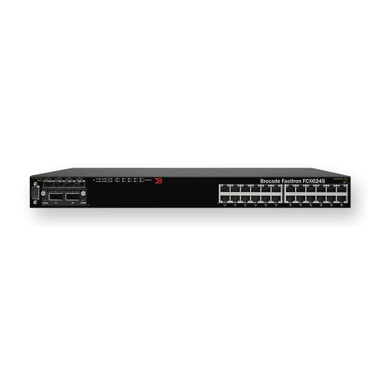
Gbps Ethernet CX4 ports on the rear panel allow stacking for up to eight units. The front panel also has a module slot for an optional two-port 10 Gbps Ethernet XFP module. Brocade FastIron CX Switch Hardware Installation Guide 53-1001978-01... - Page 12 “Hardware Specifications” on page 59. The following figures show the front panels of the FastIron CX models. For more information about Combo ports, see “Combination ports” on page 6. For more information about control features in general, see “Control features”...
- Page 13 FCX624S-HPOE front panel FastIron FCX624S-HPOE Slot 3 FIGURE 5 FCX648S-HPOE front panel FastIron FCX648S-HPOE FIGURE 6 FCX624S, FCX648S, FCX624S-F, FCX624S-HPOE, FCX648S-HPOE rear panel FIGURE 7 FCX624-E front panel Reset Diag Console Mgmt Brocade FastIron CX Switch Hardware Installation Guide 53-1001978-01...
- Page 14 The power supplies and fan trays are clearly labeled with either a green arrow with an “E”, or an orange arrow with an “I” as shown in Table Brocade FastIron CX Switch Hardware Installation Guide 53-1001978-01...
-
Page 15: Control Features
The out-of-band RJ45 management interface enables you to configure and manage the device using a third-party terminal emulation application on a directly-connected PC. Network interfaces for FCX624S, FCX648S, FCX624S-F, FCX624-HPOE, FCX648-HPOE FastIron CX devices contain the following interfaces: • 10/100/1000 Mbps ports with RJ45 copper connectors •... - Page 16 FastIron CX 10/100/1000 BASE-T ports All FastIron CX devices except for the fiber models contain 24 or 48 RJ45 ports that operate at 10 Mbps or 100 Mbps, half or full duplex, or at 1000 Mbps, full duplex. FastIron CX fiber models contain 24 or 48 SFP ports.
- Page 17 FCX648-I devices panel module (optional) on front with optional panel four-port 10 Gbps SFP+ module SFP interfaces Table 3 describes the network interfaces supported on FastIron CX devices. TABLE 3 SFP network interfaces Interface Show Media Description 1000Base-BX-D M-GBXD 1000Base-BX-U M-GBXU...
-
Page 18: Figure 13
LC cables. These devices cannot be combined in a stack with non-FastIron CX devices. For detailed information about how to configure FastIron CX devices in an IronStack topology, see the FastIron Configuration Guide. - Page 19 FCX switches include a display panel for key system and port indicators that simplifies installation and network troubleshooting. The LEDs, which are located on the front panel for easy viewing, are shown below and described in the following tables. Brocade FastIron CX Switch Hardware Installation Guide 53-1001978-01...
-
Page 20: Figure 15
The SFP port is operating at 1000 Mbps. (1F~4F) On Amber The SFP port is operating at 100 Mbps. Speed A link is not established with a remote port. FIGURE 16 System status LEDs Slot 3 System status LEDs Brocade FastIron CX Switch Hardware Installation Guide 53-1001978-01... - Page 21 FIGURE 17 Power status LEDs Power status LEDs TABLE 9 Power status LEDs Condition Status Green DC output ok DC OK DC output fail Green AC input ok AC OK AC input fail Brocade FastIron CX Switch Hardware Installation Guide 53-1001978-01...
-
Page 22: Reset
The LEDs, which are located on the front panel for easy viewing, are shown below and described in the following tables. FIGURE 18 Port status LEDs Reset Diag Console Mgmt Port status LEDs SFP or SFP+ port status LEDs Brocade FastIron CX Switch Hardware Installation Guide 53-1001978-01... - Page 23 The port has established a valid link at 10/100/1000 Mbps. Management Flashing indicates the port is transmitting and receiving user Link or Activity packets. A link is not established with a remote port. Brocade FastIron CX Switch Hardware Installation Guide 53-1001978-01...
-
Page 24: Power Supplies
The device has two power receptacles on the rear panel. Each device ships with one power supply installed. FCX624S, FCX648S, FCX624S-F, FCX624-E, FCX624-I, FCX648-E and FCX648-I devices use a 210W PSU. FCX624S-HPOE and FCX648S-HPOE devices use a 620W PSU. Brocade FastIron CX Switch Hardware Installation Guide 53-1001978-01... - Page 25 FastIron CX device to function normally. When two PSUs are installed, both "AC OK" and "DC OK" LEDs for one of the installed PSUs must be green for the FastIron CX device to function normally. HPOE and HPOE + power supplies FCX624S-HPOE and FCX648S-HPOE devices use a 620W PSU.
- Page 26 DRAFT: BROCADE CONFIDENTIAL Hardware features Brocade FastIron CX Switch Hardware Installation Guide 53-1001978-01...
-
Page 27: Installing The Fastiron Cx Switch
“Power precautions” on page 19. Unpacking the device FastIron CX devices ship with all of the items listed below. Verify the contents of your shipping container. If any items are missing, please contact the place of purchase. Package contents The following items are included in your shipping carton: •... -
Page 28: Installation Tasks
Network Manager to manage the device. Secure access to the device. FastIron Configuration Guide Installation precautions Follow all precautions when installing a Brocade device. General precautions CAUTION All fiber-optic interfaces use Class 1 lasers. Brocade FastIron CX Switch Hardware Installation Guide 53-1001978-01... -
Page 29: Lifting Precautions
Compare this total with the rating limit for the circuit. The maximum ampere ratings are usually printed on the devices near the input power connectors. Brocade FastIron CX Switch Hardware Installation Guide 53-1001978-01... -
Page 30: Preparing The Installation Site
240 VAC, 50 to 60 Hz, is within 2 m (6.6 feet) of each device and is powered from an independent circuit breaker. As with any equipment, a filter or surge suppressor is recommended. Installing the device You can install Brocade devices on a desktop or in an equipment rack. Brocade FastIron CX Switch Hardware Installation Guide 53-1001978-01... -
Page 31: Desktop Installation
59.) • Mechanical loading: Do not place any equipment on top of a rack-mounted unit. • Circuit overloading: Be sure that the supply circuit to the rack assembly is not overloaded. Brocade FastIron CX Switch Hardware Installation Guide 53-1001978-01... - Page 32 FIGURE 24 Attaching the Brackets for FCX624S, FCX648S, FCX624S-F, FCX624-HPOE, FCX648-HPOE FIGURE 25 Attaching the brackets for FCX624-E, FCX624-I, FCX648-E, and FCX648-I 3. Attach the device in the rack as illustrated in Figure Brocade FastIron CX Switch Hardware Installation Guide 53-1001978-01...
-
Page 33: Connecting Devices In A Stack
Figure 5 illustrates a ring-topology stacking configuration. You can form a stack containing up to eight FastIron CX units. To connect switches in a stack, perform the following steps: 1. Plug one end of a stack cable into one of the CX4 stacking ports of the top unit. - Page 34 FCX device. Using FCX624-E, FCX624-I, FCX648-E, and FCX648-I devices in this type of mixed stack requires your to reconfigure the default stacking ports on the other FCX device. For more information, see the FastIron Configuration Guide. Brocade FastIron CX Switch Hardware Installation Guide 53-1001978-01...
- Page 35 Reset Diag Console Mgmt Reset Diag Console Mgmt FIGURE 29 Connecting FCX624-E and FCX648-E devices in a ring stack topology Reset Diag Console Mgmt Reset Diag Console Mgmt Reset Diag Console Mgmt Brocade FastIron CX Switch Hardware Installation Guide 53-1001978-01...
-
Page 36: Powering On The System
Access the CLI by attaching a serial cable to the Console port. After you assign an IP address, you can access the system through Telnet, the Web management interface, or IronView Network Manager. Use the following steps to attach a management station to the serial port. Brocade FastIron CX Switch Hardware Installation Guide 53-1001978-01... -
Page 37: Wiring Map For Serial Cable
3 TXD (transmit data) 5 SGND (signal ground) <--------------------------> 5 SGND (signal ground) No other pins are used. NOTE As indicated in Table 16, some of the wires should not be connected. Brocade FastIron CX Switch Hardware Installation Guide 53-1001978-01... -
Page 38: Installing And Replacing A Power Supply Unit
CAUTION If you do not install a PSU in a slot, you must keep the slot panel in place. If you run the device with an uncovered slot, the system will overheat. Brocade FastIron CX Switch Hardware Installation Guide 53-1001978-01... -
Page 39: Installing Or Replacing Fan Trays On Fcx624S, Fcx648S, Fcx624S-F, Fcx624-Hpoe, And Fcx648-Hpoe Devices
5. When you are sure the fan tray has properly engaged the connector, tighten the retainer screws to secure the fan tray in the slot. NOTE The fans are controlled by software, and their speed is set according to the environmental temperature surrounding the switch. Brocade FastIron CX Switch Hardware Installation Guide 53-1001978-01... -
Page 40: Installing Or Replacing Fan Trays On Fcx624-E, Fcx624-I, Fcx648-E, And Fcx648-I Devices
5. When you are sure the fan tray has properly engaged the connector, tighten the retainer screws to secure the fan tray in the slot. NOTE The fans are controlled by software, and their speed is set according to the environmental temperature surrounding the switch. Brocade FastIron CX Switch Hardware Installation Guide 53-1001978-01... -
Page 41: Installing An Optional Module On Fcx624S, Fcx648S, Fcx624S-F, Fcx624-Hpoe
CAUTION If you do not install a module in a slot, you must keep the slot panel in place. If you run the device with an uncovered slot, the system will overheat. Brocade FastIron CX Switch Hardware Installation Guide 53-1001978-01... -
Page 42: Installing An Optional Module In Fcx624-E, Fcx624-I, Fcx648-E, And Fcx648-I Devices
If you want ports 1 and 2 on the 10 Gbps module to pass regular Ethernet traffic, you must first disable stacking on these ports. For more information, see the FastIron Configuration Guide Brocade FastIron CX Switch Hardware Installation Guide 53-1001978-01... - Page 43 CAUTION If you do not install a module in a slot, you must keep the slot panel in place. If you run the device with an uncovered slot, the system will overheat. Brocade FastIron CX Switch Hardware Installation Guide 53-1001978-01...
- Page 44 DRAFT: BROCADE CONFIDENTIAL Installing an optional module in FCX624-E, FCX624-I, FCX648-E, and FCX648-I devices Brocade FastIron CX Switch Hardware Installation Guide 53-1001978-01...
-
Page 45: Checking Network Devices And Testing Connectivity
Port Configuration – Allows read-and-write access for specific ports but not for global (system-wide) parameters. • Read Only – Allows access to the Privileged EXEC mode and CONFIG mode but only with read access. Brocade FastIron CX Switch Hardware Installation Guide 53-1001978-01... -
Page 46: Setting Passwords
4. Enter no password at the prompt. (You cannot abbreviate this command.) 5. Enter boot system flash primary at the prompt. This command causes the device to bypass the system password check. After the console prompt reappears, assign a new password. Brocade FastIron CX Switch Hardware Installation Guide 53-1001978-01... -
Page 47: Configuring Ip Addresses
FCX648SHPOE Switch(config)# ip default-gateway 192.22.3.1 NOTE You do not need to assign a default gateway address for single subnet networks. Syntax: enable [<password>] Syntax: configure terminal Syntax: [no] ip address <ip-addr> <ip-mask> Brocade FastIron CX Switch Hardware Installation Guide 53-1001978-01... -
Page 48: Devices Running Layer 3 Software
Syntax: [no] ip address <ip-addr> <ip-mask> [secondary] Syntax: [no] ip address <ip-addr>/<mask-bits> [secondary] Use the secondary parameter if you have already configured an IP address within the same subnet on the interface. Brocade FastIron CX Switch Hardware Installation Guide 53-1001978-01... - Page 49 Layer 3 Switch and other devices. You can configure up to four loopback interfaces on a Layer 3 switch. You can add up to 24 IP addresses to each loopback interface. Brocade FastIron CX Switch Hardware Installation Guide 53-1001978-01...
- Page 50 FCX624 Router(config-if-1/1/1)# no ip address 1.1.2.1 This command deletes IP address 1.1.2.1. You do not need to enter the subnet mask. To delete all IP addresses from an interface, enter the following command: Brocade FastIron CX Switch Hardware Installation Guide 53-1001978-01...
-
Page 51: Connecting Network Devices
For more information about this feature, see the FastIron Configuration Guide. FIGURE 37 UTP crossover cable 10/100BASE-TX Crossover Cable White/Orange Stripe Orange White/Green Stripe End A End B Blue White/Blue Stripe Green White/Brown Stripe Brown Brocade FastIron CX Switch Hardware Installation Guide 53-1001978-01... -
Page 52: Connecting To Workstations, Servers, Or Routers
The following sections describe these tasks. Fiber Optic transceivers Table 17 lists supported XFP transceivers (for stacking and non-stacking FCX models). Table 18 shows supported SFP and SFP+ transceivers. For information about cabling for transceivers, see Table Brocade FastIron CX Switch Hardware Installation Guide 53-1001978-01... - Page 53 (such as an equipment rack) to act as ground. 2. Remove the new transceiver from the protective packaging. 3. Gently insert the transceiver into the slot until it clicks into place. Transceivers are keyed to prevent incorrect insertion. Brocade FastIron CX Switch Hardware Installation Guide 53-1001978-01...
- Page 54 4. Observe the link and active LEDs to determine if the network connections are functioning properly. For more information about the LED indicators, refer to Table 19. Brocade FastIron CX Switch Hardware Installation Guide 53-1001978-01...
-
Page 55: Testing Connectivity
Test for connectivity by observing the LEDs related to network connection. Pinging an IP address To verify that a FastIron CX device can reach another device through the network, enter a command similar to the following at any level of the CLI. - Page 56 Check the Link LED to make sure the link is still established with the remote port. If not, take the actions described in the Meaning or Action column for the Link LED. Brocade FastIron CX Switch Hardware Installation Guide 53-1001978-01...
-
Page 57: Tracing A Route
For the indicated port, verify that both ends of the cabling (at the device and the connected device) are snug. • Verify that the device and the connected device are both powered on and operating correctly. Brocade FastIron CX Switch Hardware Installation Guide 53-1001978-01... -
Page 58: Using Virtual Cable Testing To Diagnose A Cable
Viewing the results of the cable analysis To display the results of the cable analysis, enter a command similar to the following at the Privileged EXEC level of the CLI. FCX648SHPOE Switch# show cable-diag tdr 1/1/1 Brocade FastIron CX Switch Hardware Installation Guide 53-1001978-01... -
Page 59: Digital Optical Monitoring
XFP, SFP, and SFP+ manufacturer’s recommended thresholds. For more information about digital optical monitoring, refer to FastIron Configuration Guide. Brocade FastIron CX Switch Hardware Installation Guide 53-1001978-01... - Page 60 DRAFT: BROCADE CONFIDENTIAL Troubleshooting network connections Brocade FastIron CX Switch Hardware Installation Guide 53-1001978-01...
-
Page 61: Managing The Fastiron Cx Hardware
1 -> 2 @ 61 deg-C 1 <- 2 @ 56 deg-C 2 -> 3 @ 67 deg-C 2 <- 3 @ 62 deg-C MAC 1 Temperature Readings: Current temperature : 50.5 deg-C Brocade FastIron CX Switch Hardware Installation Guide 53-1001978-01... - Page 62 FCX624 Router# temperature warning 1 85 Syntax: temperature warning <stack-unit> <value> The <stack-id> can be 1 – 8. The <value> can be 0 – 125 To disoplay the current temperature readings, enter the temp command as shown. Brocade FastIron CX Switch Hardware Installation Guide 53-1001978-01...
- Page 63 The device will automatically reset and reload the software when the internal temperature reaches or exceeds the configured shutdown level for five minutes. The system is also capable of registering negative temperature settings. Brocade FastIron CX Switch Hardware Installation Guide 53-1001978-01...
- Page 64 DRAFT: BROCADE CONFIDENTIAL Managing temperature settings To change the temperature at which the FastIron CX sends a warning, you must change the fan speed threshold. To view the current temperature thresholds, enter the show chassis command: FCX648SHPOE Switch# show chassis...
-
Page 65: Removing Mac Address Entries
Use the vlan <number> parameter to remove all MAC addresses for a specified VLAN. Displaying FastIron CX CPU usage You can display the amount of the FastIron CX CPU in use. To do so, enter the show cpu command at any level of the CLI:... -
Page 66: Hardware Maintenance Schedule
You can replace the copper and fiber optic modules (SFPs or mini-GBICs). Replacing a copper or fiber optic module You can remove an SFP from a slot and replace it with a new one while the FastIron CX is powered on and running. -
Page 67: Cabling A Fiber Optic Module
For instructions on cabling a fiber optic module refer to “Cabling a fiber optic transceiver” page 44. Cleaning the fiber optic connectors For instructions on cleaning a fiber optic module refer to “Cleaning the fiber optic connectors” page 45. Brocade FastIron CX Switch Hardware Installation Guide 53-1001978-01... - Page 68 DRAFT: BROCADE CONFIDENTIAL Replacing a copper or fiber optic module Brocade FastIron CX Switch Hardware Installation Guide 53-1001978-01...
-
Page 69: Hardware Specifications
Hardware Specifications Hardware specifications This chapter provides the hardware specifications for FastIron CX devices. Physical dimensions and weight Table 21 lists the physical dimensions and weight for the FastIron CX devices. TABLE 21 Physical dimensions and weight Model Height Width... -
Page 70: Cooling System And Fans
“E”, or an orange arrow with an “I” as shown Table 1 on page 5. For an illustration of the fan tray labels, see “Power supply and fan tray labels for FCX624-E, FCX624-I, FCX648-E, and FCX648-I devices” on page 5. Brocade FastIron CX Switch Hardware Installation Guide 53-1001978-01... - Page 71 FCX624S, FCX648S, FCX624S-F, FCX624-HPOE, and FCX648-HPOE device airflow 1 Air Inflow 2 Air outlet FIGURE 45 FCX624-E and FCX648-E device airflow Mg mt Res et Con sole Dia g 1 Air Inflow 2 Air outlet Brocade FastIron CX Switch Hardware Installation Guide 53-1001978-01...
- Page 72 FCX624-I and FCX648-I device airflow Mg mt Res et Con sole Dia g 1 Air Inflow 2 Air outlet For a complete list of regulatory compliances refer to “Regulatory compliance” on page 71. Brocade FastIron CX Switch Hardware Installation Guide 53-1001978-01...
-
Page 73: Pinouts And Signalling
Most PC serial ports require a cable with a female DB-9 connector. However, terminal connections will vary, requiring a cable with either a DB-9 or DB-25 connector, male or female. Serial cable options between the FastIron CX switch and a PC or terminal are shown in Figure... -
Page 74: Cable Specifications
1300 nm 2 – 10000 1000Base-SX LC connector for SFP module 62.5/125 .5 – 275 62.5/125 .5 – 550 50/125 .5 – 595 50/125 1500 .5 – 740 50/125 2000 .5 – 860 Brocade FastIron CX Switch Hardware Installation Guide 53-1001978-01... -
Page 75: Power Cords
509.79 W with HPOE 509.79 W with HPOE+ FCX648S-HPOE 100 - 240 VAC 3.3 - 7.8 Amps < 75 Amps peak 140.94 W 620 W maximum 542.94 W with HPOE 542.94 W with HPOE+ Brocade FastIron CX Switch Hardware Installation Guide 53-1001978-01... - Page 76 100 - 240 VAC 1.2 - 2.8 Amps < 75 Amps peak 57.36 W 210 W maximum FCX648-I 100 - 240 VAC 1.2 - 2.8 Amps < 75 Amps peak 57.36 W 210 W maximum Brocade FastIron CX Switch Hardware Installation Guide 53-1001978-01...
-
Page 77: Troubleshooting
Verify that all system components have been properly installed. If one or more components appear to be malfunctioning (such as the power cord or network cabling), test them in an alternate environment where you are sure that all the other components are functioning properly. Brocade FastIron CX Switch Hardware Installation Guide 53-1001978-01... -
Page 78: In-Band Access
Then verify that you entered the correct IP address. Also, be sure the port through which you are connecting to the switch has not been disabled. If it has not been disabled, then check the network cabling that runs between your remote location and the switch. Brocade FastIron CX Switch Hardware Installation Guide 53-1001978-01... -
Page 79: Regulatory Statements
Europe and Australia (CISPR 22 Class A Warning) This is a Class A product. In a domestic environment this product may cause radio interference in which case the user may be required to take adequate measures. Japan (VCCI) Brocade FastIron CX Switch Hardware Installation Guide 53-1001978-01... -
Page 80: Japan Power Cord
If it is sold or purchased incorrectly, it should be exchanged with a home apparatus (Class B). Russia "C " -0560, : 29 2009 . 2012 . Brocade FastIron CX Switch Hardware Installation Guide 53-1001978-01... -
Page 81: Regulatory Compliance
AS or NZS CISPR 22, Electromagnetic Compatibility Immunity: • EN 61000-6-1, Electromagnetic Compatibility, Generic Standard • EN 55024, Information Technology equipment - Immunity Characteristics Safety: • BI-NAT CSA 60950-1-03/UL 60950-1 • EN 60950-1:2001 • IEC 60950-1:2001 Brocade FastIron CX Switch Hardware Installation Guide 53-1001978-01... - Page 82 DRAFT: BROCADE CONFIDENTIAL Regulatory compliance Brocade FastIron CX Switch Hardware Installation Guide 53-1001978-01...
-
Page 83: Cautions And Danger Notices
PRECAUCIÓN Use un circuito derivado separado para cada cordón de alimentación de CA, con lo que se proporcionará redundancia en caso de que uno de los circuitos falle. Brocade FastIron CX Switch Hardware Installation Guide 53-1001978-01... - Page 84 Si usted borra accidentalmente la configuración en un sistema ya configurado, introduzca el comando write memory (escribir memoria) para guardar la configuración en ejecución en el archivo startup-config. Brocade FastIron CX Switch Hardware Installation Guide 53-1001978-01...
-
Page 85: Danger Notices
"Gefahr" weist auf eine mögliche Gefährdung hin, die zu Verletzungen oder Tod führen können. Sie finden die folgenden Warnhinweise in diesem Handbuch: Un danger attire votre attention sur un risque possible de blessure ou de décès. Ci-dessous, vous trouverez les avertissements utilisés dans ce manuel. Brocade FastIron CX Switch Hardware Installation Guide 53-1001978-01... - Page 86 PELIGRO Monte los instrumentos que instale en un bastidor o armario lo más bajos posible. Ponga el instrumento más pesado en la parte inferior y los instrumentos progresivamente más livianos más arriba. Brocade FastIron CX Switch Hardware Installation Guide 53-1001978-01...
- Page 87 Pour des raisons de sécurité, la dragonne ESD doit contenir une résistance de série 1 méga ohm. PELIGRO Por razones de seguridad, la correa de muñeca ESD deberá contener un resistor en serie de 1 mega ohmio. Brocade FastIron CX Switch Hardware Installation Guide 53-1001978-01...
- Page 88 DRAFT: BROCADE CONFIDENTIAL Danger notices Brocade FastIron CX Switch Hardware Installation Guide 53-1001978-01...
Need help?
Do you have a question about the FastIron CX and is the answer not in the manual?
Questions and answers