Table of Contents
Advertisement
Instructions
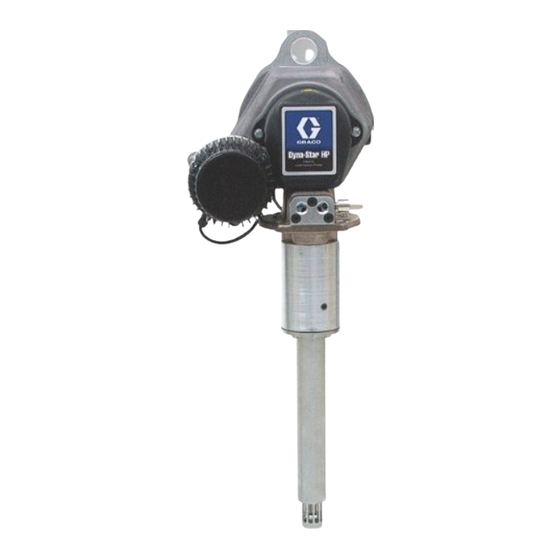
Dyna-Star
HF Pump
Provides lubricant flow and pressure to operate a single line automatic lubrication
system. For automatic lubrication systems only. For professional use only.
Not approved for use in explosive atmospheres or hazardous locations.
Important Safety Instructions
Read all warnings and instructions in this
manual. Save these instructions.
Models: Page 2
®
HP and
332514J
EN
Advertisement
Table of Contents


Need help?
Do you have a question about the Dyna-Star 77X000 and is the answer not in the manual?
Questions and answers