Table of Contents
Advertisement
Quick Links
Instructions – Parts List
Parts
STAINLESS STEEL
Dura–Flot 750 Pumps
With Severe–Duty Rod and Cylinder
Patent No. 5,456,583
Foreign Patents Pending
Read warnings and instructions.
See page 2 for model numbers and maximum
working pressures.
GRACO INC. P.O. BOX 1441 MINNEAPOLIS, MN 55440-1441
Copyright 2002, Graco Inc. is registered to I.S. EN ISO 9001
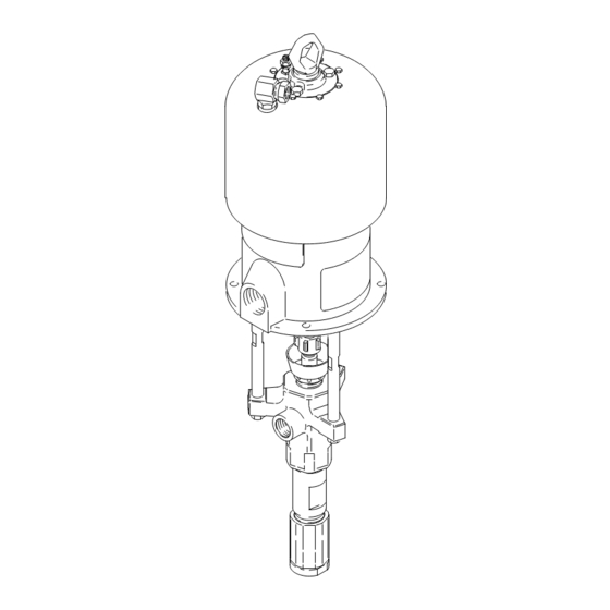
Model 237367
Model 237635
TI0483
308418G
TI0483
Advertisement
Table of Contents

Related Manuals for Graco 237367


Summary of Contents for Graco 237367
- Page 1 Foreign Patents Pending Read warnings and instructions. See page 2 for model numbers and maximum working pressures. Model 237367 Model 237635 TI0483 TI0483 GRACO INC. P.O. BOX 1441 MINNEAPOLIS, MN 55440-1441 Copyright 2002, Graco Inc. is registered to I.S. EN ISO 9001...
-
Page 2: Table Of Contents
236456, 68:1 46.9 MPa, 469 bar 0.7 MPa, 7 bar Series B Quiet Kingt Series B (6800 psi) (100 psi) 237367, Bulldogr 236456, 33:1 22.8 MPa, 228 bar 0.7 MPa, 7 bar Series A Series B (3300 psi) (100 psi) -
Page 3: Warnings
D This equipment is for professional use only. D Read all instruction manuals, tags, and labels before operating the equipment. D Use the equipment only for its intended purpose. If you are uncertain about usage, call your Graco distributor. D Do not alter or modify this equipment. Use only genuine Graco parts and accessories. - Page 4 Permanently coupled hoses cannot be repaired; replace the entire hose. D Use only Graco approved hoses. Do not remove any spring guard that is used to help protect the hose from rupture caused by kinks or bends near the couplings.
- Page 5 WARNING FIRE AND EXPLOSION HAZARD Improper grounding, poor ventilation, open flames or sparks can cause a hazardous condition and result in a fire or explosion and serious injury. D Ground the equipment and the object being sprayed. Refer to Grounding on page 7. D If there is any static sparking or you feel an electric shock while using this equipment, stop spray- ing immediately.
- Page 6 Notes 308418...
-
Page 7: Installation
NOTE: Reference numbers and letters in parentheses in the text refer to the callouts in the figures and the parts drawing. NOTE: Always use Genuine Graco Parts and Acces- sories, available from your Graco distributor. Refer to Product Data Sheet, Form No. 305722 (Bulldog 0864 Pumps) or Form No. - Page 8 Installation System Accessories (continued) A pump runaway valve (C) senses when the pump is running too fast and automatically shuts off the air to the motor. A pump which runs too fast WARNING can be seriously damaged. An air manifold (G) has a 3/4 npsm(f) swivel air A bleed-type master air valve (E) and a fluid drain inlet.
- Page 9 Installation TYPICAL INSTALLATION Pump Air Line Filter Gun Swivel Wall Bracket Bleed-Type Master Air Valve Airless Spray Gun Pump Runaway Valve (for accessories) Suction Kit Air Line Lubricator Fluid Filter Ground Wire and Clamp Bleed-Type Master Air Valve M Fluid Drain Valve (required) (required;...
-
Page 10: Operation/Maintenance
Operation/Maintenance Pressure Relief Procedure Packing Nut/Wet-Cup Before starting, fill the packing nut (8) 1/3 full with WARNING Graco Throat Seal Liquid (TSL) or compatible solvent. See Fig. 4. INJECTION HAZARD The system pressure must be manually WARNING relieved to prevent the system from starting or spraying accidentally. - Page 11 Operation/Maintenance Flush the Pump Before First Use NOTE: When changing fluid containers with the hose and gun already primed, open the drain valve (M) to The pump is tested with lightweight oil, which is left in help prime the pump and vent air before it enters the to protect the pump parts.
- Page 12 Operation/Maintenance Shutdown and Care of the Pump Flush with a fluid that is compatible with the fluid you are pumping and with the wetted parts in your system. Check with your fluid manufacturer or supplier for WARNING recommended flushing fluids and flushing frequency. Always flush the pump before fluid dries on the dis- To reduce the risk of serious injury whenever you placement rod.
-
Page 13: Troubleshooting Chart
Turn on the air just enough to start the pump. If the pump starts when the air is turned on, the obstruction is in the fluid hose or gun. NOTE: If you experience air motor icing, call your Graco distributor. 308418... -
Page 14: Service
5. Reconnect all hoses. Reconnect the ground wire if leave it attached to its mounting. it was disconnected. Fill the packing nut (8) 1/3 full of Graco Throat Seal Liquid or compatible solvent. CAUTION 6. Turn on the air supply. Run the pump slowly to ensure proper operation. - Page 15 Service Model 237367 Shown Torque to 61–75 NSm (45–55 ft-lb) Torque to 195–210 NSm (145–155 ft-lb) Torque to 68–81 NSm (50–60 ft-lb) TI0486 Fig. 5 308418...
-
Page 16: Displacement Pump
Service DISPLACEMENT PUMP SERVICE 2. Using a 2–3/4 in. socket or a pipe wrench, un- screw the intake valve (5) from the intake housing (7). Be careful to catch the intake ball (13) as you Disassembly remove the intake valve, so that it does not fall and suffer damage. - Page 17 Service 6. Shine a light into the cylinder (2) to inspect the CAUTION inner surface for scoring or wear. Remove the two seals (11) from the cylinder. To reduce the possibility of costly damage to the rod (1) and cylinder (2), always use a plastic or wooden 7.
- Page 18 Service Reassembly 4. For standard displacement pump 236456, lubricate the throat packings and place them in the outlet housing (6) in the following order, with the lips of 1. If it was necessary to remove the piston ball the v-packings facing down: the male gland (3*), housing (9) from the displacement rod (1), clean four leather v-packings (19*), one PTFErv-pack- the threads of the rod and the ball housing, and...
- Page 19 Service Torque to 61–75 NSm (45–55 ft-lb). Lips face up. Torque to 325–353 NSm (240–260 ft-lb). Lips face down. Torque to 258–285 NSm (190–210 ft-lb). See the Throat Packing Detail at left. Lubricate. See the Piston Packing Detail at left. Torque to 190–217 NSm (140–160 ft-lb).
- Page 20 Service 9. Install the seal (11*) on the intake valve (5). Lubri- 11. Install the seal (11*) on the bottom of the cylinder cate the seal and the threads of the intake valve. (2). See Fig. 9. Lubricate the seal and the threads of the cylinder.
- Page 21 Parts Part No. 237635 Pump, Series B Part No. 236460 Pump, Series B 68:1 Ratio, with King Air Motor 68:1 Ratio, with Reduced Icing Quiet King Air Motor 102Y 102Y 107{ 107{ {105 106{ 106{ {105 110{ 110{ {108 {108 These parts are included in These parts are included in Connection Kit 235417.
- Page 22 Parts Part No. 237367 Pump, Series A Part No. 237613 Pump, Series A 33:1 Ratio, with Bulldog Air Motor 33:1 Ratio, with Reduced Icing Quiet Bulldog Air Motor 102Y 102Y 107{ 107{ {105 106{ 106{ {105 110{ 110{ {108 {108...
- Page 23 Parts NOTE: The parts listed on this page are common to all Part displacement pumps covered in this manual. Refer to page Description 24 for the different packing configurations available. 189853 ROD, displacement; stainless steel 189857 CYLINDER; stainless steel * These parts are included in Repair Kit 237240, which may 236585 VALVE, intake;...
- Page 24 Packing Kits Leather Packing Kit 237240, for Standard Displacement Pump 236456, Series A Part THROAT PACKINGS: PISTON PACKINGS: LIPS FACE DOWN LIPS FACE UP Description 184223 GLAND, male; stainless steel 184173 GLAND, female; stainless steel V-PACKING; PTFE r 109303 184303 V-PACKING;...
-
Page 25: Technical Data
Maximum fluid working pressure Part No. 237635 and 236460 King Pumps: 47.6 MPa, 476 bar (6800 psi) Part No. 237367 and 237613 Bulldog Pumps: 22.8 MPa, 228 bar (3300 psi) Maximum air input pressure Part No. 237635 and 236460 King Pumps: 0.7 MPa, 7 bar (100 psi) Part No. - Page 26 (gray). Follow right to scale to read air consumption. liters/min 11.4 15.2 18.0 FLUID FLOW (NO. 10 WEIGHT OIL) Performance Data (237367 and 237613 Bulldog Pumps) KEY: Fluid Outlet Pressure – Black Curves cycles/min Air Consumption – Gray Curves scfm MPa, bar...
- Page 27 Dimensions Mounting Hole Layout Model 237367 Shown 94.28 mm (3.712”) 101.6 mm (4.0”) 94.28 mm (3.712”) 50.8 mm (2.0”) Three M16 x 2.0 Holes 11.1 mm (0.437”) 88 mm DIA (4) (3.464”) 0653 TI0483 Pump Model 237367 1105 mm 561 mm...
- Page 28 Graco distributor to the original purchaser for use. With the exception of any special, extended, or limited warranty published by Graco, Graco will, for a period of twelve months from the date of sale, repair or replace any part of the equipment determined by Graco to be defective.
Need help?
Do you have a question about the 237367 and is the answer not in the manual?
Questions and answers