Table of Contents
Advertisement
Quick Links
Instructions, Repair and Parts
Dyna-Star
HYDRAULIC RECIPROCATOR AND PUMP
- Used for dispensing lubricating fluids only -
10:1 Ratio Universal Pump and Reciprocator
600 psi (4.1 MPa, 41 bar) Maximum Hydraulic Input Pressure
7500 psi (51 MPa, 517 bar) Maximum Fluid Outlet Pressure
Model 247540: Pump, 60 lb Automatic Lube Pump Module Length
Model 247443: Pump, 120 lb Drum Length
Model 247450: Pump, 400 lb Drum Length
Important Safety Instructions
Read all warnings and instructions in this manual.
Save these instructions.
®
312350L
ti10604a
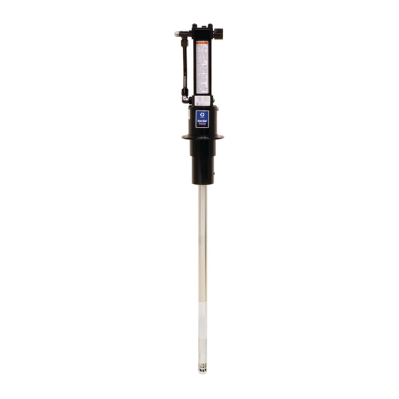
Model 247443 Shown
EN
Advertisement
Table of Contents

Related Manuals for Graco Dyna-Star 247540


Summary of Contents for Graco Dyna-Star 247540
- Page 1 Instructions, Repair and Parts ® Dyna-Star 312350L HYDRAULIC RECIPROCATOR AND PUMP - Used for dispensing lubricating fluids only - 10:1 Ratio Universal Pump and Reciprocator 600 psi (4.1 MPa, 41 bar) Maximum Hydraulic Input Pressure 7500 psi (51 MPa, 517 bar) Maximum Fluid Outlet Pressure Model 247540: Pump, 60 lb Automatic Lube Pump Module Length Model 247443: Pump, 120 lb Drum Length Model 247450: Pump, 400 lb Drum Length...
- Page 2 Warnings Warnings The following warnings are for the setup, use, grounding, maintenance, and repair of this equipment. The exclama- tion point symbol alerts you to a general warning and the hazard symbols refer to procedure-specific risks. When these symbols appear in the body of this manual or on warning labels, refer back to these Warnings. Product-specific hazard symbols and warnings not covered in this section may appear throughout the body of this manual where applicable.
- Page 3 Warnings WARNING SKIN INJECTION HAZARD High-pressure fluid from dispensing device, hose leaks, or ruptured components will pierce skin. This may look like just a cut, but it is a serious injury that can result in amputation. Get immediate surgical treatment. •...
-
Page 4: Installation
3/4 inch return line (F) on the reciprocator. to pump fluid outlet. Order valve, Part No. 111229. Contact your Graco representative for line sizing. A pump outlet drain (D) is required in your system. This Pressure Reducing Valve (N): Circulates excess... -
Page 5: Pressure Relief Procedure
Installation Grounding Pressure Relief Procedure Follow the Pressure Relief Procedure whenever you see this symbol. The equipment must be grounded to reduce the risk of static sparking. Static sparking can cause fumes to ignite or explode. Grounding provides an escape This equipment stays pressurized until pressure is wire for the electric current. -
Page 6: Typical Installation
. 2 is only a guide for selecting and installing system components and accessories. Some of the equipment is required, as noted in the key. For assistance in designing a system to suit your needs, con- tact your Graco distributor. Mount pump securely so it cannot move during operation. -
Page 7: Operation
Operation Operation Starting Pump NOTICE To prevent damage to pump, do not operate pump For the following instructions, see F . 2. without it being securely mounted to a drum cover or 1. Turn on hydraulic power supply. support. 2. Open return line shut-off valve (H) first, then slowly open the hydraulic supply shut-off valve (L). -
Page 8: Troubleshooting
Troubleshooting Troubleshooting Problem Cause Solution Pump does not run. Closed dispense valve. Pump only runs with valve open. Pressure too low. Increase supply pressure using a pressure adjusting valve. Insufficient hydraulic fluid supply. Check hydraulic supply. Adjust to a maximum of 3 gpm (11 lpm) flow. Clogged fluid outlet line, intake Relieve pressure, page 5. - Page 9 Service Service Removing Displacement Pump from Reciprocator NOTE: The reference letters used in the following Ser- vice instructions refer to the Typical Installation illustra- Disassembly tion provided on page 6. The reference numbers used in the following Service instructions refer to the Parts pages beginning on page Pump Leaks at the Fluid Fittings 36, 37 Tighten fittings (1, 5, 60;...
- Page 10 Service 7. Use a strap wrench on spacer tube (114) to unscrew Disassembly it out of the pump adapter (8) and slide it down as 1. Relieve pressure, page 5. far as it will go (F . 5). 2. Disconnect reciprocator from displacement pump (see Removing Displacement Pump from Recipro- cator, page 9).
- Page 11 Service 4. Remove retainer nut (11) and seal (44) from top of 6. Loosen nut (45a) on both ends of fluid tube (45) pump adapter (8). . 9). 7. Use a wrench to loosen elbow (1) and tee (60). 5. Remove four capscrews (46) and washers (52) from Remove fluid tube (45).
- Page 12 Service 8. Check o-rings (1a and 60a) on fittings (1 and 60) Reassembly and replace them if they are worn or damaged. Use Kit 247455. Use all new parts included in the kit. 1. Install seal (16) in bottom of cylinder cap (32) in the orientation shown in F .
- Page 13 Service 3. Install seal (44) on retainer nut (11). Install retainer 5. Install lock washers (37) and nuts (36) onto tie rods nut in pump adapter (8) (F . 14). Torque retainer (38). Torque nuts to 28-32 ft-lbs (38-43 N.m) (F nut to 54 to 56 ft-lbs (73-75 N.m).
-
Page 14: Reciprocator Repair
Reciprocator Repair Reciprocator Repair • Clean and inspect all parts for wear or damage. Replace worn parts as needed. For best results, always replace all the o-rings and seals when you disassemble the pump. Repair Kit 247455 is avail- able. Parts included in the kit are marked with an asterisk, for example (23*), in the text and drawings. - Page 15 Reciprocator Repair 5. Place bottom cap (32) in vise. Remove four cap- 8. Remove cap plate (30) (F . 19). screws (46) and lockwashers (52). 9. Use a rubber or plastic head mallet to tap the bot- tom of the displacement rod (35) and loosen cylin- der (25).
- Page 16 Reciprocator Repair 12. Secure hex end of displacement rod (34) in a vise. 1. If needed, install a new spring over trip rod as fol- Use a spanner wrench (sw) in pin holes of the piston lows (F . 23): (22) to remove the piston from the displacement •...
- Page 17 Reciprocator Repair 9. Use a spanner wrench to screw piston (22) onto NOTE: When attaching the motor housing (43) onto the displacement rod (34). Torque to 40 to 48 ft-lb (54 to bottom cylinder cap (32), be sure that the port (43b) in 65 N.m).
-
Page 18: Displacement Pump Repair
Reciprocator Repair 17. If tie rods (38) were removed, reinstall them with Displacement Pump Repair short threaded end up. The other end should be screwed about 9/16” into bottom cylinder cap (32). Disassembly NOTE: When reinstalling cylinder (25), be sure port in •... - Page 19 Reciprocator Repair Reassembly Reassembling Displacement Pump to Reciprocator 1. Clean all the parts in a compatible solvent and inspect them for wear or damage. Use all parts in the repair kit, replace other parts as necessary. NOTE: If the last letter of the Series Code is A or B, omit Step 2.
- Page 20 Reciprocator Repair 4. Screw connecting rod (107) into displacement rod 6. Use a strap wrench to screw together shovel tube (35) until holes align. Install cotter pin (204) through (117) and pump cylinder (109). holes. 7. Connect hydraulic supply and return hoses to fit- tings (5, 60).
-
Page 21: Displacement Pump Parts
Reciprocator Repair Displacement Pump Parts See page 22. Model 247540: 60# Pump Module Length Model 247443: 120# Drum Length Model 247450: 400# Drum Length Part No. Description 196184 PISTON, 50:1 196185 WASHER, retainer 104† 114171 PACKING, u-cup 106† 100065 BALL 15R104 ROD, connecting, model 247540 15M382 ROD, connecting, model 247443 15M445 ROD, connecting, model 247450... - Page 22 Reciprocator Repair † † † † † † ti10608a ti10609a Assembled / Cutaway View Using nut (113), torque the pump cylinder 109 to the extension tube (114) at 45 to 55 ft-lb (61 to 75 N.m). Torque the shovel rod (108) to the piston (102) at 25 to 30 ft-lb (34 to 41 N.m). Torque the piston (102) to the extension rod (107) at 25 to 30 ft-lb (34 to 41 N.m).
-
Page 23: Reciprocator Parts
Reciprocator Parts Reciprocator Parts ti10462a Torque to 170-180 in-lbs (19-20 N.m) Torque to 42-45 in-lbs (4-5 N.m). Torque to 54-56 ft-lbs (73-76 N.m). Torque to 54-56 in-lbs (6.0-6.5 N.m). Torque to 40-48 ft-lbs (54-65 N.m) Torque to 28-32 ft-lbs (38-43 N.m). Assemble with lips facing up. - Page 24 Reciprocator Parts Reciprocator Parts Ref. Ref. Part No. Description Qty. Part No. Description Qty. 40 179885 LABEL, Warning 106470 ELBOW, straight thread, 3/4-16 HOUSING, motor unf-2a x 3/4-16 unf-2a, 37° flare includes item 1a 44*† 114179 PACKING, u-cup 110987 O-RING 217221 TUBE, inlet 178179 WASHER, sealing 120557 CAPSCREW, sch, 3/18-16...
- Page 25 Pump Parts (F . 34) Pump Parts (F . 34) Model 247540: 60# Pump Module Length Model 247443: 120# Drum Length Model 247450400# Drum Length Ref No. Part No. Description RECIPROCATOR, page 23 202* 192533 SEAL, gasket 112154 DISPLACEMENT PUMP 206...
-
Page 26: Technical Data
Technical Data Technical Data Dyna-Star Pump Metric Max grease output pressure 7500 psi 51 MPa, 517 bar Max hydraulic fluid input pressure 600 psi 4.1 MPa, 41 bar Max hydraulic fluid input volume 3 gpm, 60 cpm 11.7 lpm, 60 cpm Hydraulic fluid consumption rate 6.5 ounces per cycle or 1 gallon 0.195 liter per cycle or 1 liter per... -
Page 27: Dimensions And Mounting Hole Layout
Technical Data Dimensions and Mounting Hole Layout 3/4” - 16 JIC 3.5 (88.9 mm) 37° flare (m) minimum diameter clearance hole 3/4 npt Hydraulic Outlet 14.75 in. (375 mm) 1/8 npt throat seal 3.536 in. weep port (90.424 mm) 3.536 in. (90.424 mm) 33.9 in. -
Page 28: Graco Standard Warranty
With the exception of any special, extended, or limited warranty published by Graco, Graco will, for a period of twelve months from the date of sale, repair or replace any part of the equipment determined by Graco to be defective.
Need help?
Do you have a question about the Dyna-Star 247540 and is the answer not in the manual?
Questions and answers