Table of Contents
Advertisement
Instructions
Air-Operated
Diaphragm Pumps
For fluid transfer applications. For professional use only. Only models marked with (*) are
approved for use in European explosive atmosphere locations.
100 psi (0.7 MPa, 7 bar) Maximum Fluid Working Pressure
100 psi (0.7 MPa, 7 bar) Maximum Air Input Pressure
ACETAL*, POLYPROPYLENE, AND PVDF
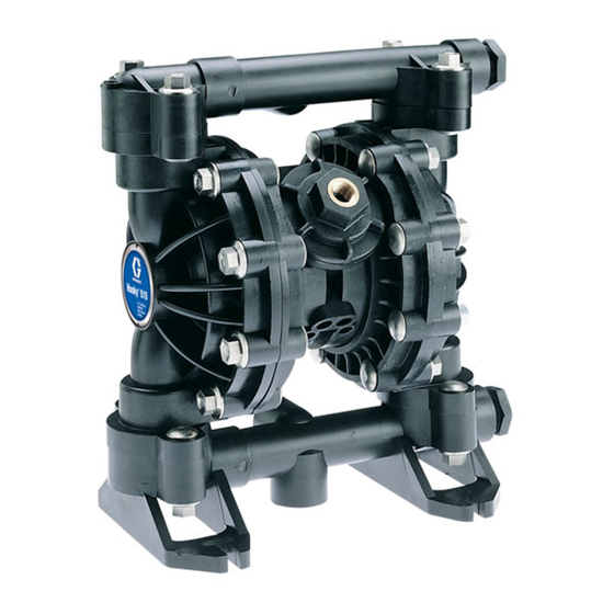
Husky™ 515
Model No. D 5 1 _ _ _ Acetal NPT Pumps
Model No. D 5 2 _ _ _ Polypropylene Pumps
Model No. D 5 5 _ _ _ PVDF NPT Pumps
Model No. D 5 A _ _ _ Acetal BSPT Pumps
Model No. D 5 B _ _ _ Polypropylene BSPT Pumps
Model No. D 5 E _ _ _ PVDF BSPT Pumps
Model No. D 9 1 _ _ _ Acetal NPT Pumps
Model No. D 9 A _ _ _ Acetal BSPT Pumps
For Additional Models, see Table of Contents
ALUMINUM* AND STAINLESS STEEL*
Husky™ 716
Model No. D 4 D _ _ _ Stainless Steel BSPT Pumps, Remote
Model No. D 5 3 _ _ _ Aluminum NPT Pumps
Model No. D 5 4 _ _ _ Stainless Steel NPT Pumps
Model No. D 5 C _ _ _ Aluminum BSPT Pumps
Model No. D 5 D _ _ _ Stainless Steel BSPT Pumps
Model No. D 9 4 _ _ _ Stainless Steel NPT Pumps
Model No. D 9 D _ _ _ Stainless Steel BSPT Pumps
For Additional Models, see Table of Contents
*These models are certified:
II 2 GD
Ex h IIC 66°C...135°C Gb
Ex h IIIC T135°C Db
Important Safety Instructions
Read all warnings and instructions in this manual.
Save these instructions.
Refer to the Pump Matrix on page 22 to determine the
model number of your pump.
ATEX T-code rating is dependent on the temperature
of the fluid being pumped. Fluid temperature is limited
by the materials of the pump interior wetted parts.
See Technical Data for the maximum fluid operating
temperature for your specific pump model.
308981ZAT
EN
9065A
Husky 515
9246A
Husky 716
Advertisement
Table of Contents

Related Manuals for Graco Husky 515 D51 Series


Summary of Contents for Graco Husky 515 D51 Series
- Page 1 Instructions Air-Operated Diaphragm Pumps 308981ZAT For fluid transfer applications. For professional use only. Only models marked with (*) are approved for use in European explosive atmosphere locations. 100 psi (0.7 MPa, 7 bar) Maximum Fluid Working Pressure 100 psi (0.7 MPa, 7 bar) Maximum Air Input Pressure ACETAL*, POLYPROPYLENE, AND PVDF Husky™...
-
Page 2: Table Of Contents
Husky 515 and 716 Performance Charts ..35 Graco Standard Warranty ....38 WARNING EQUIPMENT MISUSE HAZARD Equipment misuse can cause the equipment to rupture or malfunction and result in serious injury. - Page 3 WARNING TOXIC FLUID HAZARD Hazardous fluid or toxic fumes can cause serious injury or death if splashed in the eyes or on the skin, inhaled, or swallowed. • Know the specific hazards of the fluid you are using. • Do not lift a pump under pressure. If dropped, the fluid section may rupture. Always follow the •...
-
Page 4: Installation
These pumps can be used in a variety of selecting and installing system components. installations. Be sure the mounting surface can Contact your Graco distributor for assistance in support the weight of the pump, hoses, and planning a system to suit your needs. - Page 5 3. Connect remaining ends of tubes to external air sig- ardous fluids. nal, such as Graco’s Cycleflo (P/N 195264) or Cycle- flo II (P/N195265) controllers. CAUTION NOTE: the air pressure at the connectors must be at The pump exhaust air may contain contaminants.
- Page 6 Installation Fluid Pressure Relief Valve Air Exhaust Ventilation CAUTION Read TOXIC FLUID HAZARD on page 3. Some systems may require installation of a pressure relief valve at the pump outlet to prevent overpressur- Read FIRE AND EXPLOSION ization and rupture of the pump or hose. See Fig. 1. HAZARD on page 3.
- Page 7 Installation ABOVE-GROUND TRANSFER INSTALLATION A Pump B Bleed-type master air valve (required for pump) C Electrically conductive air supply line D Air line quick disconnect E Master air valve (for accessories) F Air line filter G Pump air regulator H Fluid drain valve (required) Fluid regulator (optional) K Electrically conductive fluid supply hose L Fluid suction line...
- Page 8 Installation Grounding Ground all of this equipment: • Pump: The metal pump has a grounding strip in WARNING front of the center housing. The acetal pump has a grounding screw on the top manifold. Connect the FIRE AND EXPLOSION HAZARD non-clamp end of the ground wire to the grounding strip or grounding screw, and connect the clamp This pump must be grounded.
- Page 9 Installation Changing the Orientation of the Fluid Inlet Torque to 80 to 90 in-lb (9 to 10 NSm). See and Outlet Ports (Husky 515) Torque Sequence, page 29. You can change the orientation of the fluid inlet and out- outlet let ports by repositioning the manifolds.
- Page 10 Install Reed Switch 1. Shut off air to pump and remove valve cover (A). 2. Remove lower carriage and replace with new carriage assembly (2), so magnet faces end of valve chamber. 3. Replace valve cover. Torque to 80 to 100 in-lb (9.0 to 13.6 N•m).
-
Page 11: Operation
Operation Pressure Relief Procedure 6. Place the end of the fluid hose (K) into an appropriate container. WARNING 7. Close the fluid drain valve (H). PRESSURIZED EQUIPMENT HAZARD 8. With the pump air regulator (G) closed, open all The equipment stays pressurized until pressure is bleed-type master air valves (B, E). -
Page 12: Maintenance
Maintenance Lubrication Tightening Threaded Connections The air valve is lubricated at the factory to operate with- Before each use, check all hoses for wear or damage out additional lubrication. If you want to provide addi- and replace as necessary. Check to be sure all threaded tional lubrication, remove the hose from the pump air connections are tight and leak-free. -
Page 13: Troubleshooting
Troubleshooting Read Pressure Relief Procedure on page 11, and relieve the pressure before you check or service the equipment. Check all possible problems and causes before disassembling the pump. PROBLEM CAUSE SOLUTION Pump will not cycle, or cycles once and Air valve is stuck or dirty. -
Page 14: Service
Service Air Valve (Husky 515 and Husky 716 pumps without reed switch) NOTE: Air Valve Repair Kit 241657 is available. Parts included in the kit are marked with a dagger (†) in Fig. 6 and in the Parts Drawings and Lists. A tube of general purpose grease 111920 is supplied in the kit. Service the air valve as follows. - Page 15 Air Valve (Husky 515 and Husky 716 pumps with reed switch) NOTE: Air Valve Repair Kit 25C469 is available. Parts included in the kit are marked with a dagger (†) in Fig. 7 and in the Parts Drawings and Lists. A tube of general purpose grease 111920 is supplied in the kit. Service the air valve as follows.
- Page 16 Service Ball or Duckbill Check Valves Inlet and Outlet for Pumps with Duckbill Check Valves NOTE: Fluid Section Repair Kit D05XXX is available. See page 22 to order the correct kit for your pump. Parts Pumps with duckbill check valves are shipped with the included in the kit are marked with a double dagger (‡) inlet manifold on top and the outlet manifold on the in Fig.
- Page 17 Service Husky 515 Husky 716 Torque to 80 to 90 in-lb (9 to 10 N-m). See Torque Sequence, page 29. 9067A Fig. 8 Torque to 80 to 90 in-lb (9 to 10 N-m). See Torque Sequence, page 29. 9081A Fig. 9 308981 17...
- Page 18 Service Diaphragms (Husky 515) NOTE: Fluid Section Repair Kit D05XXX is available. See page 22 to order the correct kit for your pump. Parts included in the kit are marked with a double dagger ( ) in Fig. 10 and in the Parts Drawings and Lists. General pur- ‡...
- Page 19 Service Diaphragms (Husky 515) HD Overmolded Diaphragm ‡ Included in Fluid Section Repair Kit D05XXX Install with lips facing out of center housing (11). Torque to 35 to 45 in-lb (4.0 to 5.1 N-m). Apply grease. The words “AIR SIDE” on diaphragms (and on backup diaphragms required on PTFE models) must face toward diaphragm shaft (15).
- Page 20 Service Diaphragms (Husky 716) NOTE: Fluid Section Repair Kit D05XXX is available. See page 22 to order the correct kit for your pump. Parts included in the kit Fig. 11 are marked with a double dagger (‡) in and in the Parts Drawings and Lists. General purpose grease 111920 and Adhe- Fig.
- Page 21 Service Diaphragms (Husky 716) ‡ Included in Fluid Section Repair Kit D05XXX Install with lips facing out of center housing (11). Torque to 35 to 45 in-lb (4.0 to 5.1 N-m). HD Overmolded Diaphragm Apply grease. The words “AIR SIDE” on diaphragms (and on backup diaphragms used on PTFE models) must face toward diaphragm shaft (15).
-
Page 22: Husky 515 And Husky 716 Pump Matrix
Husky 515 and Husky 716 Pump Matrix Your Model No. is marked on the pump’s serial plate. To determine a pump Model No. from the following matrix, select the six digits that describe the pump, working from left to right. The first digit is always D, designating Husky diaphragm pumps. - Page 23 Additional Husky 515 and Husky 716 Pumps Model Pump Same As: Except for: 241564 D51211 Has open downward port. Use inlet manifold 241558. 26C021 D52966 Has split inlets/outlets. 241565 D52911 Has open downward port. Use inlet manifold 241557. 26C022 D52911 Has split inlets/outlets.
-
Page 24: Husky 515 And Husky 716 Common Parts
Husky 515 and Husky 716 Common Parts See the Pump Matrix on page 22 for an explanation of the Matrix Column and the Digit. Air Motor Parts List (Matrix Column 2) Guide Parts List (Matrix Column 4) Dígit Ref. Part Description Qty. - Page 25 Husky 515 Parts Drawing † Included in Air Valve Repair Kit 241657 or 25C469 ‡ Included in Fluid Section Repair Kit D05XXX These parts are unique to the remote operated air grounding screw motor. (acetal pump only) 9064B 308981 25...
- Page 26 Husky 515 Fluid Section Parts List See the Pump Matrix on page 22 for an explanation of the Matrix Column and the Digit. See page 24 for Air Motor Parts List (Matrix Column 2) Husky 515 Fluid Section Parts List (Matrix Column 3) Ref.
-
Page 27: Husky 716 Parts Drawing
Husky 716 Parts Drawing † Included in Air Valve Repair Kit 241657 ‡ Included in Fluid Section Repair Kit D05XXX * These parts are unique to the remote operated air motor. Grounding Detail 9070A 308981 27... - Page 28 Husky 716 Fluid Section Parts List See the Pump Matrix on page 22 for an explanation of the Matrix Column and the Digit. See page 24 for Air Motor Parts List (Matrix Column 2) Husky 716 Fluid Section Parts List (Matrix Column 3) Ref.
-
Page 29: Torque Sequence
Torque Sequence Husky 716 Always follow torque sequence when instructed to torque fasteners. 1. Left/Right Fluid Covers Torque bolts to 80-90 in-lb (9-10 N•m) Husky 515 1. Left/Right Fluid Covers Torque bolts to 80-90 in-lb (9-10 N•m) 1 1 1 1 FRONT VIEW 2. -
Page 30: Husky 515 Technical Data
PVDF pumps ..............8.5 lb (3.9 kg) *These temperatures are based onmechanical stress only andmay be altered significantly by pumping certain chem- icals. Consult engineering guides for chemical compatibilities and temperature limits, or contact your Graco distribu- tor. -
Page 31: Husky 515 Dimensions
Husky 515 Dimensions FRONT VIEW 1/2 npt(f) or bspt(f) Fluid Outlet * 4.70 in. 5.01 in. (119 mm) (127 mm) 1/4 npt(f) Air Inlet * Pumps with duckbill check valves are shipped with the inlet manifold on top and the outlet manifold on the bottom. -
Page 32: Husky 716 Technical Data
Stainless steel pumps ............18 lb (8.2 kg) *These temperatures are based on mechanical stress only and may be altered significantly by pumping certain chemicals. Consult engineering guides for chemical compatibilities and temperature limits, or contact your Graco distributor. -
Page 33: Reed Switch Technical Data
Reed Switch Technical Data Contact Ratings State ................Normally open Voltage . -
Page 34: Husky 716 Dimensions
Husky 716 Dimensions FRONT VIEW 4.25 in. 4.44 in. * Pumps with duckbill check 3/4 npt(f), bspt(f) or (108.0 mm) (112.8 mm) valves are shipped with the bspp(f) inlet manifold on top and the outlet manifold on the 1/4 npt(f) bottom. -
Page 35: Husky 515 And 716 Performance Charts
Husky 515 and 716 Performance Charts Fluid Outlet Pressure Test Conditions: Pump tested in water with inlet submerged. (0.7, 7) Fluid Pressure Curves A at 100 psi (0.7 MPa, 7 bar) air pressure B at 70 psi (0.48 MPa, 4.8 bar) air pressure C at 40 psi (0.28 MPa, 2.8 bar) air pressure (0.55, 5.5) (0.41, 4.1) - Page 36 Husky 515 and 716 Performance Charts Air Consumption Test Conditions: Pump tested in water with inlet submerged. Air Consumption Curves (0.84) A at 100 psi (0.7 MPa, 7 bar) air pressure B at 70 psi (0.48 MPa, 4.8 bar) air pressure C at 40 psi (0.28 MPa, 2.8 bar) air pressure (0.70) (0.56)
- Page 37 California Proposition 65 CALIFORNIA RESIDENTS WARNING: Cancer and reproductive harm – www.P65warnings.ca.gov. 308981 37...
-
Page 38: Graco Standard Warranty
Graco’s written recom- mendations. This warranty does not cover, and Graco shall not be liable for general wear and tear, or any malfunction, damage or wear caused by faulty installation, misapplication, abrasion, corrosion, inadequate or improper maintenance, negli- gence, accident, tampering, or substitution of non-Graco component parts.
Need help?
Do you have a question about the Husky 515 D51 Series and is the answer not in the manual?
Questions and answers