Table of Contents
Advertisement
Quick Links
Instructions, Repair and Parts
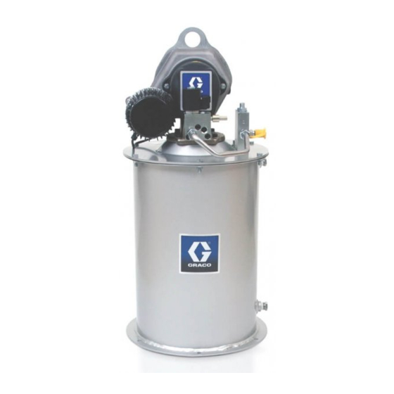
Dyna-Star
Pump System
Provides lubricant flow and pressure to operate a single line parallel automatic lubrication
system. For automatic lubrication systems only.
Not approved for use in explosive atmospheres or hazardous locations.
Important Safety Instructions
Read all warnings and instructions in this
manual and the Dyna-Star HP and HF
Pump instruction manual. Save all
instructions.
Graco Tank Injector Lubrication Systems
3500 psi (24.1 MPa, 241 bar) Maximum Working
Pressure
Models
All models include Tube-in-Tube design, vent valve,
cover and tank.
Size
System
35/60
90/120
Models
Pound
Pound
77X100
X
77X101
®
HP
Dip
Stick
X
X
X
332540B
EN
Advertisement
Table of Contents

Related Manuals for Graco Dyna-Star 77X100


Summary of Contents for Graco Dyna-Star 77X100
- Page 1 Read all warnings and instructions in this manual and the Dyna-Star HP and HF Pump instruction manual. Save all instructions. Graco Tank Injector Lubrication Systems 3500 psi (24.1 MPa, 241 bar) Maximum Working Pressure Models All models include Tube-in-Tube design, vent valve, cover and tank.
- Page 2 Warnings Warnings The following warnings are for the setup, use, grounding, maintenance, and repair of this equipment. The exclama- tion point symbol alerts you to a general warning and the hazard symbols refer to procedure-specific risks. When these symbols appear in the body of this manual or on warning labels, refer back to these Warnings. Product-specific hazard symbols and warnings not covered in this section may appear throughout the body of this manual where applicable.
- Page 3 Warnings WARNING WARNING WARNING WARNING PRESSURIZED EQUIPMENT HAZARD Over-pressurization can result in equipment rupture and serious injury. • A pressure relief valve is required at each pump outlet. • Follow Pressure Relief Procedure in this manual before servicing. EQUIPMENT MISUSE HAZARD Misuse can cause death or serious injury.
- Page 4 Warnings WARNING WARNING WARNING WARNING BURN HAZARD Equipment surfaces and fluid that’s heated can become very hot during operation. To avoid severe burns: • Do not touch hot fluid or equipment. PERSONAL PROTECTIVE EQUIPMENT Wear appropriate protective equipment when in the work area to help prevent serious injury, including eye injury, hearing loss, inhalation of toxic fumes, and burns.
-
Page 5: Typical Installation: Injector System
Typical Installation: Injector System Typical Installation: Injector System The installation shown in below is only a guide for selecting and installing system components. Contact your Graco distributor for assistance in planning a system to suit your needs. Controller Capabilities Low Reservoir... -
Page 6: Installation
NOTE: Cable wiring harness kits are available from slowly loosen fitting only until fitting is loose and no Graco. See Parts page 11 for a complete list of available more lubricant or air is leaking from fitting as shown in kits. -
Page 7: Operation
Operation Operation 1. Mount Reservoir on sturdy, flat surface. Note loca- tion of Fill Port (G) and Lubricant Outlet Connection • Read and follow instructions supplied with each sys- (A) for easy access once installed. tem component. 2. Connect High Pressure Lubricant Supply Line (D) to •... - Page 8 Operation Filling Reservoir NOTICE To prevent damage to the unit: • Check Breather vent (J) for proper operation before filling reservoir. • Open Overflow Port (H) before filling for visual inspection of lubricant level. • Do not fill beyond Overflow Port (H). •...
-
Page 9: Parts List
Parts List Parts List Model 77X100: Dyna-Star Pump, 60#, Dip Stick, Reservoir, Cover, Vent Valve Model 77X101: Dyna-Star Pump, 90#, Dip Stick, Reservoir, Cover, Vent Valve Ref. Part No. Description 77X011 KIT, pump and vent valve, includes 1a and 1b, Dyna-Star 60#, models 77X100, see instruc- tion manual 332514 77X012 KIT, pump and vent valve,... -
Page 10: Parts Drawing
Parts Drawing Parts Drawing Model 77X100: Dyna-Star Pump, 60#, Dip Stick, Reservoir, Vent Valve Model 77X101: Dyna-Star Pump, 90#, Dip Stick, Reservoir, Vent Valve 3m/3n 332540B... -
Page 11: Technical Data
Technical Data Technical Data Maximum working pressure 3500 psi (24.1 MPa, 241 bar Pump wetted parts See Dyna-Star HP or HF Pump manual: 332514 Vent valve wetted parts See Dyna-Star HP or HF Vent Valve Kit manual: 332519 Reservoir wetted parts steel, buna-n rubber Reservoir overflow port size 1/2 inch npt... - Page 12 Dimensions Dimensions 60 lb Models 90 lb Models US (inch) Metric (cm) US (inch) Metric (cm) 30.5 77.47 38.0 96.52 14.5 36.83 14.5 36.83 1/2 inch npt 1/2 inch npt 1/2 inch-14 npt 1/2 inch-14 npt 14.5 36.83 14.5 36.83 19.4 49.28 27.0...
- Page 13 Notes Notes 332540B...
-
Page 14: Graco Standard Warranty
With the exception of any special, extended, or limited warranty published by Graco, Graco will, for a period of twelve months from the date of sale, repair or replace any part of the equipment determined by Graco to be defective.
Need help?
Do you have a question about the Dyna-Star 77X100 and is the answer not in the manual?
Questions and answers