Table of Contents
Advertisement
Instructions
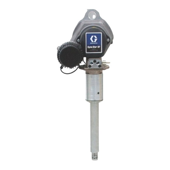
Dyna-Star
HF Pump
Provides lubricant flow and pressure to operate a single line automatic lubrication
system. For automatic lubrication systems only. For professional use only.
Not approved for use in explosive atmospheres or hazardous locations.
Important Safety Instructions
Read all warnings and instructions in this
manual. Save these instructions.
Models: Page 2
®
HP and
332514J
EN
Advertisement
Table of Contents

Related Manuals for Graco Dyna-Star 77X012


Summarization of Contents
Instructions
Important Safety Instructions
General safety warnings and advice for operating the equipment.
Warnings
Fire and Explosion Hazard
Hazards associated with flammable fluids and ignition sources.
Skin Injection Hazard
Risks from high-pressure fluid piercing the skin.
Pressurized Equipment Hazard
Risks related to equipment rupture due to over-pressurization.
Pressurized Aluminum Parts Hazard
Hazards from incompatible fluids reacting with aluminum parts.
Equipment Misuse Hazard
Dangers arising from improper use or operation.
Moving Parts Hazard
Risks of injury from moving mechanical components.
Burn Hazard
Risks of severe burns from hot equipment surfaces and fluids.
Personal Protective Equipment
Recommended protective gear to prevent injuries during operation.
Typical Installation: Injector System
Key
Explains the components and labels shown in the installation diagram.
Typical Installation: Series Progressive System
Key
Explains the components and labels shown in the installation diagram.
Installation
Pressure Relief
Procedure to safely release system pressure before servicing or maintenance.
Pump Module
Description and reference to the pump module components.
Heavy Equipment Hazard
Safety warning regarding the risks of lifting and moving heavy equipment.
Wiring
Grounding
Importance of bonding equipment to reduce static shock risk.
System Configuration and Wiring
Overview of system setup and wiring considerations.
Fuses
Requirements and recommendations for fuse installation to prevent damage.
Installation Instructions
Steps for wiring installation and component connections.
24 VDC With Signal Input
Wiring diagram for 24 VDC operation using signal input.
24 VDC With External Relay
Wiring diagram for 24 VDC operation using an external relay.
DC Models - Motor Control Board
Detailed explanation of the DC model motor control board and its functions.
Current Control and Flow Motor Control Settings
How to adjust current and flow settings on the motor control board.
Operation
Priming
Procedure for priming the pump and expelling air from the system.
Fill Reservoir
Instructions and precautions for filling the system reservoir.
Shutdown
Steps for safely shutting down the lubrication system.
Troubleshooting
Pump Not Powering On
Steps to diagnose and fix issues where the pump does not power on.
Pump Powered On, Not Cycling
Troubleshooting steps for when the pump is on but not operating.
Pump Cycles Continuously
Resolving issues where the pump cycles without stopping.
No Lubricant Output
Diagnosing and fixing problems with no lubricant being dispensed.
Pump Cycling Slow
Troubleshooting steps for a slow-cycling pump.
Pressure Not Building
Addressing issues where pump pressure is not developing correctly.
Red Fault LED Blinking
Interpreting fault codes indicated by the red LED on the control board.
Over Current Fault
Diagnosing and resolving over current fault conditions.
Locked Rotor Fault
Troubleshooting steps for a locked rotor fault.
Low or High Voltage Fault
Addressing issues related to incorrect input voltage.
Motor Temperature High
Diagnosing and fixing motor overheating problems.
Missing Temperature Sensor
Troubleshooting a missing or faulty temperature sensor.
Control Board Temperature High
Diagnosing and resolving overheating of the control board.
HALL Sensor Cable Issues
Troubleshooting loose or damaged HALL sensor cables.
Motor Runs, Pump Does Not
Steps to fix when the motor operates but the pump does not.
Erratic Control Board LEDs
Diagnosing and fixing erratic blinking of control board LEDs.
Repair
Seal Replacement
Procedure for replacing seals in the pump assembly.
Disassembly
Steps to take apart the pump for maintenance or repair.
Repair
Reassembly
Steps for reassembling the pump after repair or seal replacement.
Repair: Motor Replacement
Disassembly
Steps to disassemble the unit for motor replacement.
Repair: Motor Replacement
Reassembly
Steps for reassembling the motor and related components.
Repair: Motor Control Board Replacement
Disassembly
Steps to disassemble the unit for control board replacement.
Repair: Motor Control Board Replacement
Reassembly
Steps for reassembling the motor control board and housing.
Parts List
Main Assembly All Models
Detailed list of parts for the main assembly of all pump models.
Gear Box
Parts list specific to the gear box assembly.
HP Model Pump Lower
Parts list for the HP model pump lower assembly.
HF Model Pump Lower
Parts list for the HF model pump lower assembly.
Pump Lower Parts
Specific parts breakdown for the pump lower section.
Cable Harness Kits
List of available cable harness kits for the pump.
Repair Kits
List of available repair kits for various pump components.
Accessories
List of optional accessories available for the pump.
Dimensions
Performance Charts
Charts detailing pump performance characteristics based on current and pressure.
Graco Standard Warranty
Graco Information
Contact information and resources for Graco products and support.
Need help?
Do you have a question about the Dyna-Star 77X012 and is the answer not in the manual?
Questions and answers