Table of Contents
Advertisement
Quick Links
Instructions, Repair and Parts
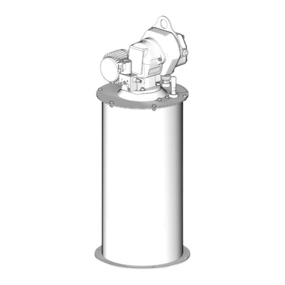
Dyna-Star HP Pump
System
Provides lubricant flow and pressure to operate a single-line parallel automatic lubrication
system. For automatic lubrication systems only. For professional use only.
Not approved for use in explosive atmospheres or hazardous (classified) locations.
Models
3500 psi (24.1 MPa, 241 bar) Maximum Working Pressure
See page 3 for model information and approvals.
Important Safety Instructions
Read all warnings and instructions in this
manual and the Dyna-Star HP and HF Pump
before using the equipment. Be familiar with the
proper control and usage of the equipment.
Save these instructions.
Related Manuals
Find English manuals and any available translations at
www.graco.com.
English
Manual
Description
Number
332514
Dyna-Star HP and HF Pump
332515
Dyna-Star HP or HF Pump Low Level Indicator
Kit; Dip Stick Kit
332518
Dyna-Star HP and HF Pump Auto-Fill Shut Off Kit
332519
Dyna-Star HP Vent Valve Kit
Models 77X100 and 77X101 shown
332540K
EN
Advertisement
Table of Contents

Related Manuals for Graco Dyna-Star HP 77X100


Summary of Contents for Graco Dyna-Star HP 77X100
-
Page 1: Related Manuals
Dyna-Star HP and HF Pump before using the equipment. Be familiar with the proper control and usage of the equipment. Save these instructions. Related Manuals Find English manuals and any available translations at www.graco.com. English Manual Description Number 332514... -
Page 2: Table Of Contents
California Proposition 65 ....17 Graco Standard Warranty....18... -
Page 3: Models
Models Models All models include Tube-in-Tube design, vent valve, cover, and tank. Size Maximum System Follower Auto-Fill Working Approvals 35/60 90/120 Models Stick Level Plate* Shut Off Pressure❊ Pound Pound 77X100 3500 psi (24.1 MPa. 77X101 241 bar) 77X102 77X103 77X104 77X105 77X300... -
Page 4: Safety Symbols
Safety Symbols Safety Symbols The following safety symbols appear throughout this manual and on warning labels. Read the table below to understand what each symbol means. Symbol Meaning Symbol Meaning Do Not Place Hands or Other Body Burn Hazard Parts Near Fluid Outlet Do Not Stop Leaks with Hand, Equipment Misuse Hazard Body, Glove or Rag... -
Page 5: General Warnings
General Warnings General Warnings The following warnings apply throughout this manual. Read, understand, and follow the warnings before using this equipment. Failure to follow these warnings can result in serious injury. WARNING FIRE AND EXPLOSION HAZARD When flammable fluids are present in the work area, such as gasoline and windshield wiper fluid, be aware that flammable fumes can ignite or explode. - Page 6 General Warnings WARNING EQUIPMENT MISUSE HAZARD Misuse can cause death or serious injury. • Do not operate the unit when fatigued or under the influence of drugs or alcohol. • Do not exceed the maximum working pressure or temperature rating of the lowest rated system component.
-
Page 7: Typical Installation
Typical Installation Typical Installation Injector System The installation shown in F . 1 is only a guide for selecting and installing system components and accessories. Contact your Graco distributor for assistance in designing a system. Key: Lubricant Outlet Connection Reservoir Pump... -
Page 8: Series Progressive System
Series Progressive System The installation shown in F . 2 is only a guide for selecting and installing system components and accessories. Contact your Graco distributor for assistance in designing a system. Key: Lubricant Outlet Connection† †The pump outlet requires modification to convert an Injector based system to Series Progressive system. -
Page 9: Installation
Dyna-Star HP Vent V.alve kit manual, see Related Manuals, page 1. NOTE: Cable wiring harness kits are available from Graco. See Cable Harness Kits (all models), page 15, Auto-Fill Shut Off for a complete list of available kits. The auto-fill shut off refills the grease reservoir instead Fuses of using the fill port (G). -
Page 10: Operation
Operation Operation The reference letters in the following instructions refer to Typical Installation, page 7. Pressure Relief Procedure COMPONENT RUPTURE HAZARD Follow the Pressure Relief Procedure whenever The maximum working pressure of each component you see this symbol. in the system may not be the same. To reduce the risk of over-pressurizing any component in the sys- tem, be sure you know the maximum working pres- sure of each component. -
Page 11: Fill The Reservoir
Operation Fill the Reservoir There are two methods to fill the reservoir: Port Fill and Auto-Fill Shut Off. Port Fill NOTICE To prevent damage to the equipment: • Check breather vent (J) for proper operation before filling the reservoir. • Open the overflow port (H) before filling for visual inspection of the lubricant level. -
Page 12: Recycling And Disposal
Recycling and Disposal Recycling and Disposal End of Product Life At the end of the product’s useful life, dismantle and recycle it in a responsible manner. • Perform the Pressure Relief Procedure, page 10. • Drain and dispose of fluids according to applicable regulations. -
Page 13: Parts
Parts Parts Model 77X100: Dyna-Star Pump, 60#, Dip Stick, Reservoir, Cover, Vent Valve Model 77X101: Dyna-Star Pump, 90#, Dip Stick, Reservoir, Cover, Vent Valve Model 77X300: Dyna-Star Pump, 60#, Dip Stick, Reservoir, Cover Model 77X301: Dyna-Star Pump, 90#, Dip Stick, Reservoir, Cover Ref. -
Page 14: Model 77X102: Dyna-Star Pump, 60#, Auto-Fill Shut Off, Reservoir, Cover, Vent Valve
Parts Model 77X102: Dyna-Star Pump, 60#, Auto-Fill Shut Off, Reservoir, Cover, Vent Valve Model 77X103: Dyna-Star Pump, 90#, Auto-Fill Shut Off, Reservoir, Cover, Vent Valve Ref. Part No. Description 77X011 KIT, pump and vent valve, includes 1a and 1b, Dyna-Star 60#, models 77X100 77X012 KIT, pump and vent valve, includes 1a and 1b, Dyna-Star... -
Page 15: Model 77X104: Dyna-Star Pump, 60#, Low Level, Reservoir, Cover, Vent Valve
Parts Model 77X104: Dyna-Star Pump, 60#, Low Level, Reservoir, Cover, Vent Valve Model 77X105: Dyna-Star Pump, 90#, Low Level, Reservoir, Cover, Vent Valve Model 77X304: Dyna-Star Pump, 60#, Low Level, Reservoir, Cover Model 77X305: Dyna-Star Pump, 90#, Low Level, Reservoir, Cover Model 133846: Dyna-Star Pump, 60#, Low Level, Follower Plate, Reservoir, Cover, Vent Valve Cable Harness Kits (all models) -
Page 16: Dimensions
Dimensions Dimensions 60 lb Models 90 lb Models US (in.) Metric (cm) US (in.) Metric (cm) 30.5 77.47 38.0 96.52 14.5 36.83 14.5 36.83 1/2 in.npt 1/2 in.npt 1/2 in.-14 npt 1/2 in.-14 npt 14.5 36.83 14.5 36.83 19.4 49.28 27.0 36.83 7/16 in. -
Page 17: Technical Specifications
Technical Specifications Technical Specifications Dyna-Star HP Pump System Metric Maximum working pressure* 3500 psi 24.1 MPa, 241 bar Wetted Parts See Dyna-Star HP and HF Pump manual, Related Manuals, Pump Wetted Parts page 1. See Dyna-Star HP Vent Valve Kit manual, Related Manuals, Vent Valve Wetted Parts page 1. -
Page 18: Graco Standard Warranty
With the exception of any special, extended, or limited warranty published by Graco, Graco will, for a period of twelve months from the date of sale, repair or replace any part of the equipment determined by Graco to be defective.
Need help?
Do you have a question about the Dyna-Star HP 77X100 and is the answer not in the manual?
Questions and answers