Extron electronics DTP T USW 233 User Manual
Dtp systems.
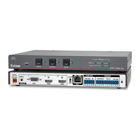
three input switcher with integrated dtp transmitter
Hide thumbs
Also See for DTP T USW 233:
- Setup manual (4 pages) ,
- Setup manual (4 pages) ,
- User manual (39 pages)

Related Manuals for Extron electronics DTP T USW 233


Summary of Contents for Extron electronics DTP T USW 233
- Page 1 User Guide DTP Systems DTP T USW 233 Three Input Switcher with Integrated DTP Transmitter 68-2490-01 Rev. E 02 18...
-
Page 2: Safety Instructions
Safety Instructions Safety Instructions • English Istruzioni di sicurezza • Italiano AVVERTENZA: Il simbolo, , se usato sul prodotto, serve ad WARNING: This symbol, ,when used on the product, is avvertire l’utente della presenza di tensione non isolata pericolosa intended to alert the user of the presence of uninsulated dangerous all’interno del contenitore del prodotto che può... - Page 3 より 『Extron Safety www.extron.com and Regulatory Compliance Guide』 (P/N 68-290-01) をご覧ください。 Copyright © 2013 - 2018 Extron Electronics. All rights reserved. Trademarks All trademarks mentioned in this guide are the properties of their respective owners. The following registered trademarks( ®...
- Page 4 FCC Class A Notice This equipment has been tested and found to comply with the limits for a Class A digital device, pursuant to part 15 of the FCC rules. The Class A limits provide reasonable protection against harmful interference when the equipment is operated in a commercial environment.
- Page 5 Software Commands Commands are written in the fonts shown here: ^AR Merge Scene,,Op1 scene 1,1 ^B 51 ^W^C [01] R 0004 00300 00400 00800 00600 [02] 35 [17] [03] E X! *X1%* X2)* X2#* X2! NOTE: For commands and examples of computer or device responses mentioned in this guide, the character “0”...
-
Page 7: Table Of Contents
............1 ........... 16 About this Guide ..........1 Contact Closure Control ........16 About the DTP T USW 233 Switcher ....1 Simple Instruction Set Control ......17 STP Cable ............2 Host-to-Switcher Communications ....17 Control Communications ........ 2 Switcher-Initiated Messages ...... - Page 8 DTP T USW 233 • Contents viii...
-
Page 9: Introduction
Figure 1. Typical Switching Transmitter Application The DTP T USW 233 is housed in a half rack width metal enclosure. It can be set on a tabletop, mounted in a rack, or mounted under or through furniture. The included external desktop 12 VDC power supply accepts 100 to 240 VAC, 50-60 Hz. A single power supply connected to either unit can power both units through the STP cable. -
Page 10: Stp Cable
Transmits HDMI or analog video, control, and analog audio up to 230 feet (70 meters) over a single STP cable — The DTP T USW 233 provides high reliability and maximum performance on an economical and easily installed cable infrastructure. - Page 11 HDCP compliance for quick, reliable switching in professional AV environments. Compatible with all DTP 230 receivers, and DTP 230-enabled products — Enables mixing and matching with desktop and wallplate receivers, as well as other DTP 230-enabled products to meet application requirements. DTP T USW 233 • Introduction...
-
Page 12: Installation And Operation
Installation and Operation This section describes the installation and the operation of the DTP T USW 233, including: Mounting the Unit • • Connections and Reset Button Operation • • Troubleshooting — If No Image Appears Mounting the Unit Mounting instructions can be found in Mounting the Switcher on page 31. -
Page 13: Connections And Reset Button
HDBaseT-enabled receiver type —Set this switch to HDBT position. The TP output consists of HDMI with embedded audio plus RS-232 and IR. The switcher and receiver each requires its own 12 VDC power supply. DTP T USW 233 • Installation and Operation... - Page 14 • If you have removed the ground jumpers (see Disconnecting the Ground page 32) because of ground potential differences, the DTP T USW 233 cannot extend analog audio. The connected receiver outputs no analog audio. • The analog audio can be assigned to a specific input or set to be always...
-
Page 15: Connector And Cable Details
RGBHV RGBS/RGsB Green Green Ground Ground Blue Blue 4, 5 H sync C sync Red return Red return Green return Green return V sync Blue return Blue return Figure 3. VGA Connector DTP T USW 233 • Installation and Operation... - Page 16 Loosely place the included tie wrap around the HDMI connector and the LockIt lacing bracket as shown ( While holding the connector securely against the lacing bracket, use pliers or similar tools to tighten the tie wrap, then remove any excess length ( DTP T USW 233 • Installation and Operation...
- Page 17 ATTENTION: Do not use Extron UTP23SF-4 Enhanced Skew-Free AV UTP cable or STP201 cable to link the switching transmitter and receiver. The DTP T USW 233 does not work properly with these cables. N’utilisez pas le câble AV Skew-Free UTP version améliorée UTP23SF d’Extron ou le câble STP201 pour relier les produits XTP avec les émetteurs ou les récepteurs DTP.
-
Page 18: Power Supply Wiring
• Ne pas étamer les conducteurs avant de les insérer dans le connecteur. Les câbles étamés ne sont pas aussi bien fixés dans le connecteur et pourraient être retirés. DTP T USW 233 • Installation and Operation... - Page 19 10) permettent de repérer le pôle négatif du cordon d’alimentation. To verify the polarity before connection, plug in the power supply with no load and check the output with a voltmeter. DTP T USW 233 • Installation and Operation...
-
Page 20: Front Panel Configuration Port
NOTE: A front panel configuration port connection and a rear panel Remote RS-232 port connection can both be active at the same time. If commands are sent simultaneously to both, the command that reaches the processor first is handled first. DTP T USW 233 • Installation and Operation... -
Page 21: Operation
CONFIG HDCP MODE NORMAL AUTO DTP T USW 233 Figure 9. DTP T USW 233 Front Panel Controls and Indicators Auto Switch LED Input 1 through 3 buttons Input 1 through 3 LEDs Mode button Normal button Auto(switch) button Status LEDs... -
Page 22: Front Panel Operations
NOTE: The switcher must be in normal (manual) mode. An input can also be selected using an RS-232 or USB device or a contact closure device Remote Control, beginning on page 16). (see DTP T USW 233 • Installation and Operation... -
Page 23: Troubleshooting - If No Image Appears
Ensure that the proper signal format is supplied. Check the cabling and make corrections as necessary. Call the Extron S3 Sales & Technical Support Hotline if necessary. See the Extron website for the Extron office nearest you. DTP T USW 233 • Installation and Operation... -
Page 24: Remote Control
Simple Instruction Set Control • Product Configuration Software The DTP T USW 233 switcher can be remotely controlled via its rear panel Remote RS-232 port, its front panel configuration (USB) port, and its rear panel Remote Contact port. Remote control devices can be: •... -
Page 25: Simple Instruction Set Control
Simple Instruction Set Control The DTP T USW 233 switching transmitter can be remotely controlled using SIS commands from a host device such as a computer or control system via its rear panel Remote RS-232 port (see item on page 7) or front panel configuration (USB) port (see item page 12). -
Page 26: Using The Command And Response Table
= Firmware version number to second decimal place (x.xx) X1& = Verbose mode 0 = Clear/none 2 = Tagged responses for queries 1 = Verbose mode (default) 3 = Verbose mode and tagged for queries DTP T USW 233 • Remote Control... -
Page 27: Command And Response Table For Sis Commands
= Input HDCP status = No source detected = Source detected with HDCP = Source detected without HDCP = Output HDCP status = No sink detected = Sink detected with HDCP = Sink detected without HDCP DTP T USW 233 • Remote Control... - Page 28 = EDID See the table above. = User EDID location , or = Raw EDID data 128 or 256 bytes of hexadecimal data = Resolution and rate in plain text Example: • 1920x1200 00Hz DTP T USW 233 • Remote Control...
- Page 29 = Embed audio = Embedded digital audio = Auto select (default) = Analog audio input = Tally pin mode when channel is muted = Always on (default) = Blink when muted = Off when muted DTP T USW 233 • Remote Control...
- Page 30 = Firmware version number to second decimal place (x.xx) X1& = Verbose mode 0 = Clear/none 2 = Tagged responses for queries 1 = Verbose mode (default) 3 = Verbose mode and tagged for queries DTP T USW 233 • Remote Control...
-
Page 31: Installing The Software
( Download Jump to the nearest page of downloads by clicking the desired filtering TIP: letter ( dialog box appears (see figure 13 on the next page). Log in DTP T USW 233 • Remote Control... - Page 32 Web browser choice and its security settings. Click to confirm that you want to run the installation ( For a firmware download, exit this procedure and go to Updating the Firmware page 26. DTP T USW 233 • Remote Control...
-
Page 33: Starting The Program
Device Discovery 1 1 1 1 1 1 1 1 2 2 2 2 2 2 2 2 Figure 15. Device Discovery Screen Select (click) your DTP T USW 233 unit (see figure 15, DTP T USW 233 • Remote Control... -
Page 34: Updating The Firmware
(see figure File Download Security Warning on the next page). The PC downloads the firmware update from the Extron website and starts the Extron Installation Program to extract the firmware file. DTP T USW 233 • Remote Control... - Page 35 DTP T USW Firmware Upgrade v2.02 3 3 3 3 3 3 3 3 Folder where firmware is saved. 4 4 4 4 4 4 4 4 Figure 17. Extracting Firmware Upgrade Files DTP T USW 233 • Remote Control...
- Page 36 Starting the Program, beginning on page 25). Click > . The software asks you to confirm that you Device Menu Update firmware want to continue the update (see figure 18 on the next page). DTP T USW 233 • Remote Control...
- Page 37 Update Firmware Click to continue ( Update The Firmware Loader utility tests the connection, installs the update, and then verifies the firmware. At the conclusion of the process, the utility reports Upload Complete DTP T USW 233 • Remote Control...
- Page 38 . The Product Configuration Software window returns to the front. Close Click the in the connection tab to completely disconnect the program from the unit Starting the Program, on page 25. and then reconnect the program as described in DTP T USW 233 • Remote Control...
-
Page 39: Reference Information
(voir Disconnecting the Ground à la terre page 32). . The 1-inch high, half rack width DTP T USW 233 switching transmitter can be placed on a table, mounted in a rack, or mounted under a desk or table. Tabletop Use Affix the included rubber feet to the bottom of the unit and place it in any convenient location. -
Page 40: Ul Rack-Mounting Guidelines
(as suggested by a missing or unstable picture), remove the ground connection between the units as follows: NOTE: Once you have removed the ground jumpers, the DTP T USW 233 cannot extend analog audio and one unit cannot remotely power the other. No analog audio is output and the paired receiver requires its own dedicated power supply. - Page 41 « Classe 2 » ou « LPS » et normée 12 Vcc, 1,0 A minimum. Utilisez toujours une source d’alimentation fournie ou recommandée par Extron. L’utilisation d’une source d’alimentation non autorisée annule toute conformité réglementaire et peut endommager la source d’alimentation ainsi que le produit final. DTP T USW 233 • Reference Information...
- Page 42 Extron Electronics makes no further warranties either expressed or implied with respect to the product and its quality, performance, merchantability, or fitness for any particular use. In no event will Extron Electronics be liable for direct, indirect, or consequential damages resulting from any defect in this product even if Extron Electronics has been advised of such damage.
Need help?
Do you have a question about the DTP T USW 233 and is the answer not in the manual?
Questions and answers