
Related Manuals for Extron electronics DTP T HWP 232 D


Summary of Contents for Extron electronics DTP T HWP 232 D
- Page 1 User Guide HDMI Transmitters DTP T HWP 232/332 D DTP T UWP 232/332 D HDMI Twisted Pair Extender Transmitters 68-2547-01 Rev. A 03 14...
-
Page 2: Safety Instructions
Safety Instructions Safety Instructions • English Инструкция по технике безопасности • Русский WARNING: This symbol, , when used on the product, is intended to ПРЕДУПРЕЖДЕНИЕ: Данный символ, , если указан на продукте, alert the user of the presence of uninsulated dangerous voltage within the предупреждает... - Page 3 FCC Class A Notice This equipment has been tested and found to comply with the limits for a Class A digital device, pursuant to part 15 of the FCC rules. The Class A limits provide reasonable protection against harmful interference when the equipment is operated in a commercial environment.
- Page 4 Conventions Used in this Guide Notifications The following notifications are used in this guide: CAUTION: A caution indicates a situation that may result in minor injury. ATTENTION: Attention indicates a situation that may damage or destroy the product or associated equipment. NOTE: A note draws attention to important information.
-
Page 5: Table Of Contents
Contents Introduction Remote Control ............1 ........... 16 About this Guide ..........1 Contact Closure Control ........16 About the DTP T HWP D and DTP T UWP D Simple Instruction Set Control ......17 Extenders ............1 Host-to-Extender Communications ....17 Twisted Pair Cable Advantages ....... -
Page 7: Introduction
230 ' Projector Extron DTP T HWP 232 D Tx Transmitter A Typical DTP T HWP 232 D and DTP T UWP 232 D Application Figure 1. A Typical Transmitter and Receiver Application DTP T HWP/UWP 232/332 D Transmitters • Introduction... -
Page 8: Twisted Pair Cable Advantages
DTP T HWP D and DTP T UWP D systems consist of a transmitter (Tx) and a receiver (Rx). The transmitters and corresponding compatible receivers are sold separately. Each purchased transmitter is shipped with a single external desktop 12 VDC power supply that accepts 100 to 240 VAC, 50-60 Hz input. -
Page 9: Features
Features Transmits single link HDMI-D signals over one STP cable — Twisted pair cables provide an economical, easily installed cable solution. Transmits single link HDMI-D and VGA signals over one STP cable (UWP models) — Twisted pair cables provide an economical, easily installed cable solution. Supports DDC and HDCP transmission —... -
Page 10: Installation And Operation
Installation and Operation This section describes the installation and the operation of the extenders, including: • Mounting the Transmitter • DTP T HWP 232 and 332 D Connections DTP T UWP 232 and 332 D Connections • • TP Cable Termination and Recommendations •... -
Page 11: Site Preparation And Wall Box Installation
Site Preparation and Wall Box Installation Choose a location that allows cable runs without interference. Allow enough depth for both the wall box and the cables. Install the cables into the wall, furniture, or conduits before installing the wall plate. NOTE: The extender units are very deep and have connectors on the back side. -
Page 12: Mud Ring Installation
Feed the twisted pair cables and, if applicable, the power cables through the opening and through the wall box punch-out holes, securing them with cable clamps to provide strain relief. NOTES: • In order to fit in the wall box, the twisted pair cables and RJ-45 connectors should not have a boot installed. -
Page 13: Final Installation
Final Installation After testing and making any adjustments, do the following: At the power outlet, unplug the power supply. NOTE: One power supply can power both the transmitter and the receiver (see Power Supply Wiring on page 13). Mount the transmitter into the wall box or mud ring and attach the supplied Decora faceplate to the unit (see figure 2 on page 5). -
Page 14: Dtp T Hwp 232 And 332 D Connections
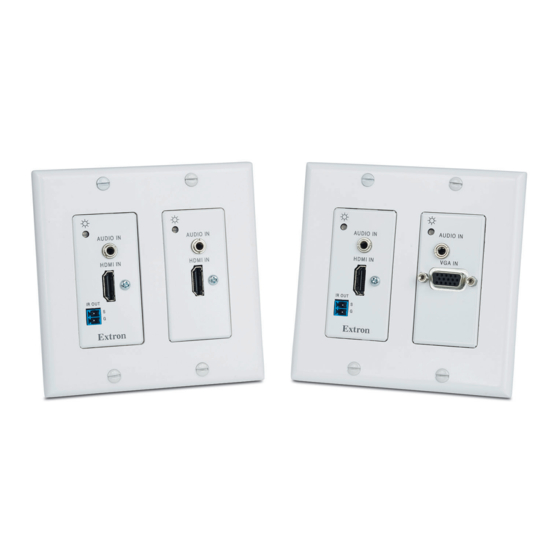
DTP T HWP 232 and 332 D Connections Front Panel AUTO SW AUDIO IN AUDIO IN HDCP HDMI IN HDMI IN CONFIG IR OUT Extron DTP T HWP 232/332 D Figure 4. DTP T HWP 232 and 332 D Front Panel Connectors Front Panel Audio input connector —... -
Page 15: Rear Panel
Rear Panel DTP T HWP/UWP 232/332 D Figure 6. DTP T HWP 232 and 332 D Rear Panel Connectors Rear Panel DC power input connector — Plug the included external 12 VDC power supply into either this 2-pole connector (see Power supply wiring on page 13 to wire the power connector) or the power input connector on the receiver (see the user guide of your... -
Page 16: Dtp T Uwp 232 And 332 D Connections
DTP T UWP 232 and 332 D Connections Front Panel AUTO SW AUDIO IN AUDIO IN AUDIO IN HDCP VGA IN HDMI IN HDMI IN CONFIG IR OUT Extron 332 D DTP T UWP 232/332 D Figure 7. DTP T UWP 232 and 332 D Front Panel Connectors Front Panel Audio input connector —... -
Page 17: Rear Panel
Rear Panel DTP T HWP/UWP 232/332 D Figure 8. DTP T UWP 232 and 332 D Rear Panel Connectors Rear Panel DC power input connector — Plug the included external 12 VDC power supply into either this 2-pole connector (see Power supply wiring on page 13 to wire the power connector) or the power input connector on the receiver (see the User Guide of your... -
Page 18: Tp Cable Termination And Recommendations
TP Cable Termination and Recommendations Figure 9 details the recommended termination of both ends of TP cables with RJ-45 connectors in accordance with the TIA/EIA-T568B wiring standard. Pins: TIA/EIA 12345678 T568-B Wire color White-orange Orange White-green Blue White-blue Green White-brown Brown TP Wires Figure 9. -
Page 19: Power Supply Wiring
Power Supply Wiring NOTES: • Only one power supply is required. A single power supply connected to either unit in the pair powers both units. • A power supply is included with each individually-packaged transmitter. Figure 10 shows how to wire the connector. Snap the provided ferrite bead onto the DC power cable, between the power supply and the connector on the unit. -
Page 20: Rs-232 And Ir Connector Wiring
RS-232 and IR Connector Wiring Remote RS-232 and Contact Closure Connector Wire the rear Remote RS-232 and contact closure connector as shown in figure 11. Connected RS-232 and Tx/Rx Contact Closure Device Pins Pins Pin 2 for contact closure control Pin 1 for contact closure control Ground Transmit pin on connected unit... -
Page 21: Operation
Operation AUTO SW AUTO SW AUDIO IN AUDIO IN AUDIO IN AUDIO IN HDCP HDCP VGA IN HDMI IN HDMI IN HDMI IN CONFIG CONFIG IR OUT IR OUT Extron Extron DTP T HWP 232/332 D DTP T UWP 232/332 D Front Panel Front Panel Figure 14. -
Page 22: Remote Control
Remote Control This section includes: Contact Closure Control • • Simple Instruction Set Control The DTP T HWP D and DTP T UWP D family of transmitters can be remotely controlled via their front panel configuration (USB) port, rear panel Remote RS-232 port, and rear panel Remote Contact port. -
Page 23: Simple Instruction Set Control
Examples of the extender-initiated messages are listed below: © Copyright 20yy Extron Electronics DTP T HWP 232 D nnnn The extender issues the copyright message when it first powers on. is the firmware version number and is the part number. -
Page 24: Using The Command And Response Table
Using the Command and Response Table command and response table begins on page 20. Symbols are used throughout the table to represent variables in the command and response fields. Command and response examples are shown throughout the table. The ASCII to HEX conversion table below is for use with the command and response table. - Page 25 X1& = Verbose mode 0 = clear/none 1 = verbose mode (default) 2 = tagged responses for queries 3 = verbose mode and tagged for queries = Force VGA to DVI out (UWP models only) 0 = HDMI (default) 1 = force VGA input to be DVI output = Pixel phase value 0 to 63, default is 32 = Total pixels value...
-
Page 26: Command And Response Table For Sis Commands
Command and Response Table for SIS Commands SIS Command Response Additional Description Command Function (Host to Unit) (Unit to Host) Select and view input Select an input •All Select input to transmit to the connected receiver. Example: Select input 1. In01•All View input selection Input... - Page 27 SIS Command Response Additional Description Command Function (Host to Unit) (Unit to Host) Picture adjustment (RGB input only, UWP models only ) X3)] Set pixel phase value PHAS Phas2* X3)] Increment pixel phase value = Pixel phase (0-63, default is 3 2+PHAS Phas2* X3)]...
- Page 28 SIS Command Response Additional Description Command Function (Host to Unit) (Unit to Host) EDID Minder NOTE: See table 1 for the EDID values. Assign EDID to an input Defaults: 50 (HDMI inputs), 03 (VGA EDID EdidA inputs) Save the EDID of the connected Save EDID of display connected to the EDID EdidS...
- Page 29 SIS Command Response Additional Description Command Function (Host to Unit) (Unit to Host) Video mute Enable video mute Output no video signal. Vmt1 Disable video mute Output selected video input. Vmt0 View video mute status Mute status = (0 = off, 1 = on) Video breakaway Select program video input only = input number 0 - 2 only...
-
Page 30: Reference Information
Reference Information This section includes Decora template dimensions for installation of the DTP T HWP D and DTP T UWP D family of transmitters. Decora Template Dimensions To create a template, use the dimensions shown on figure 14. NOTES: • The drawing is not full size or to scale. - Page 31 Extron Warranty Extron Electronics warrants this product against defects in materials and workmanship for a period of three years from the date of purchase. In the event of malfunction during the warranty period attributable directly to faulty workmanship and/or materials, Extron Electronics will, at its option, repair or replace said products or components, to whatever extent it shall deem necessary to restore said product to proper operating condition, provided that it is returned within the warranty period, with proof of purchase and description of malfunction to: USA, Canada, South America,...
Need help?
Do you have a question about the DTP T HWP 232 D and is the answer not in the manual?
Questions and answers