Extron electronics DTP T USW 333 Setup Manual
Switching video transmitter
Hide thumbs
Also See for DTP T USW 333:
- User manual (42 pages) ,
- User manual (27 pages) ,
- User manual (41 pages)
Table of Contents
Advertisement
Quick Links
DTP T USW 333 • Setup Guide
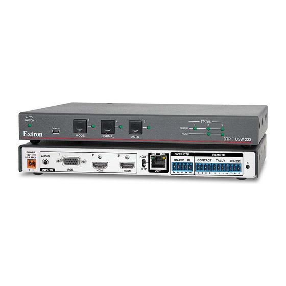
This guide provides instructions for an experienced installer to set up and operate the
Extron DTP T USW 333 switching video transmitter. The DTP T USW 333 transmitter switches among
an analog video and two digital (HDMI) video inputs and, paired with a compatible receiver, can
extend the selected signal up to 330 feet (100 m). If the selected input is HDMI, the extended video
signal is HDCP-compliant.
POWER
1
12V
AUDIO
--A MAX
RGB, Y, R-Y, B-Y
INPUTS
10
3
Installation
Step 1 — Mounting
Turn off or disconnect all equipment power sources and mount the transmitter as required.
Step 2 — Making Connections
Inputs
a
Input 1 (RGB) connector — Connect a VGA cable between this port and the VGA output port of the analog video source.
b
Input 2 and 3 (HDMI) connectors — Connect HDMI cables between these ports and the HDMI output ports of the digital video
sources.
NOTE:
LockIt
See the
c
Audio input — Connect an unbalanced stereo audio source to this 3.5 mm mini stereo jack for an analog audio input.
NOTE:
Audio is not embedded in the HDMI signal; it is transmitted simultaneously and is present on all inputs.
Over DTP RS-232 and IR pass-through
d
RS-232 and IR connector — To pass serial or infrared data or control signals on the Over
DTP RJ-45 output, connect the controlling device to the transmitter via the RS-232 and IR
captive screw connector. Connect the device to be controlled to the receiver.
DTP output to receiver
ATTENTION:
Do not connect this device to a computer data or telecommunications network.
e
DTP RJ-45 connector — Connect the transmitter DTP Out port to the DTP In port on the receiver. Extron
recommends that you terminate both cable ends in accordance with the following specifications, at a
minimum:
•
TIA/EIA T 568B
•
24 AWG, solid conductor
Signal LED — Lights when the unit is outputting a TMDS clock signal on the DTP output.
Link LED — Lights when a valid link is established between the units on the DTP cable.
Remote control
f
Remote Contact port — If desired, for contact closure control, plug a locally-constructed contact closure control device into this
3.5 mm, 4-pole captive screw port. Momentarily short the pin for the desired input (1, 2, or 3) to G to select that input. To force an
input to be always selected, leave the short in place.
NOTES:
•
Contact closure control overrides front panel input selections.
•
For contact closure control, auto-input switching mode must be off (see
2
HDMI
1
2
Lacing Brackets
®
on page 3 of this guide to securely fasten the HDMI connectors to the transmitter.
• CAT 6a, shielded
OVER DTP
SIG
LINK
3
RS-232
HDMI
DTP OUT
Tx
Rx
2
5
Selecting the switch mode
REMOTE
IR
CONTACT
TALLY
RS-232
G
Tx
Rx
1
2
3
G
1
2
3 + V
Tx
4
6
7
Pins:
12345678
TP Wires
on the next page).
RESET
Rx
G
8
9
IR Device
Rx
Tx
Gnd
Tx
Rx
Gnd
RS-232 Device
TIA/EIA T
568B
Pin
Wire color
1
White-orange
2
Orange
3
White-green
4
Blue
5
White-blue
Green
6
7
White-brown
8
Brown
1
Advertisement
Table of Contents

Related Manuals for Extron electronics DTP T USW 333


Summary of Contents for Extron electronics DTP T USW 333
-
Page 1: Remote Control
This guide provides instructions for an experienced installer to set up and operate the Extron DTP T USW 333 switching video transmitter. The DTP T USW 333 transmitter switches among an analog video and two digital (HDMI) video inputs and, paired with a compatible receiver, can extend the selected signal up to 330 feet (100 m). -
Page 2: Reset Button
Reset button — This button initiates two levels of reset. For different reset levels, use an RS-232 Device Extron Tweeker or small screwdriver to press and hold the recessed button either while the switcher is running or while applying power. See the DTP T USW 333 User Guide, available at www.extron.com, for details. Power Smooth Power connector —... -
Page 3: Application Diagram
While holding the connector securely against the lacing bracket, use pliers or similar tools to tighten the tie wrap, then remove any excess length. Application Diagram Extron Extron TouchLink Control DTP T USW 333 System DTP Transmitter Extron DTP HDMI 330 D Rx TCP/IP Receiver... - Page 4 Extron USA - East +1.714.491.1500 +1.919.850.1000 +31.33.453.4040 +91.80.3055.3777 +1.714.491.1517 FAX +1.919.850.1001 FAX +31.33.453.4050 FAX +91.80.3055.3737 FAX 68-2564-50 Rev . A © 2014 Extron Electronics All rights reserved. All trademarks mentioned are the property of their respective owners. www.extron.com 01 14...
Need help?
Do you have a question about the DTP T USW 333 and is the answer not in the manual?
Questions and answers