Extron electronics DTP T USW 233 Setup Manual
Switching video transmitter
Hide thumbs
Also See for DTP T USW 233:
- Setup manual (4 pages) ,
- User manual (42 pages) ,
- User manual (39 pages)
Table of Contents
Advertisement
Quick Links
DTP T USW 233 • Setup Guide
This guide provides instructions for an experienced installer to set up and operate the
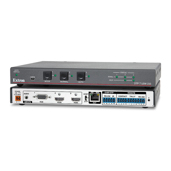
Extron DTP T USW 233 switching video transmitter. The DTP T USW 233 transmitter switches among
an analog video and two digital (HDMI) video inputs and, paired with a compatible receiver, can
extend the selected signal up to 230 feet (70 m). If the selected input is HDMI, the extended video
signal is HDCP-compliant.
POWER
1
12V
AUDIO
--A MAX
RGB, Y, R-Y, B-Y
INPUTS
J J
C C
Installation
Step 1 — Mounting
Turn off or disconnect all equipment power sources and mount the transmitter as required.
Step 2 — Making Connections
Inputs
Input 1 (RGB) connector — Connect a VGA cable between this port and the VGA output port of the analog video source.
A
Input 2 and 3 (HDMI) connectors — Connect HDMI cables between these ports and the HDMI output ports of the digital video
B
sources.
LockIt
NOTE: See the
Audio input — Connect an unbalanced stereo audio source to this 3.5 mm mini stereo jack for an analog audio input.
C
NOTE: Analog input audio is not embedded in the HDMI signal; it is transmitted separately and is present for any selected input.
Over DTP RS-232 and IR pass-through
RS-232 and IR connector — To pass serial or infrared data or control signals on the Over
D
DTP RJ-45 output, connect the controlling device to the transmitter via the RS-232 and IR
captive screw connector. Connect the device to be controlled to the receiver.
DTP output to receiver
DTP RJ-45 connector — Connect the transmitter DTP Out port to the DTP In port on the
E
receiver. Extron recommends that you terminate both cable ends in accordance with the
following specifications, at a minimum:
•
TIA/EIA T 568B
•
24 AWG, solid conductor
ATTENTION: Do not connect this device to a computer data or telecommunications network.
Signal LED — Lights when the unit is outputting a TMDS clock signal on the DTP output.
Link LED — Lights when a valid link is established between the units on the DTP cable.
Remote control
Remote Contact port — If desired, for contact closure control, plug a locally-contructed contact closure control device into this
F
3.5 mm, 4-pole captive screw port. Momentarily short the pin for the desired input (1, 2, or 3) to G to select that input. To force an
input to be always selected, leave the short in place.
NOTES:
•
Contact closure control overrides front panel input selections.
•
For contact closure control, auto-input switching mode must be off (see
2
HDMI
A A
B B
Lacing Brackets
®
on page 3 of this guide to securely fasten the HDMI connectors to the transmitter.
• Shielded cable
OVER DTP
SIG
LINK
3
RS-232
HDMI
DTP OUT
Tx
Rx
B B
E E
Selecting the switch mode
REMOTE
IR
CONTACT
TALLY
RS-232
G
Tx
Rx
1
2
3
G
1
2
3 + V
Tx
D D
F F
G G
Pins:
12345678
TP Wires
on the next page).
RESET
Rx
G
H H
I I
IR Device
Rx
Tx
Gnd
Tx
Rx
Gnd
RS-232 Device
TIA/EIA T
568B
Pin
Wire color
1
White-orange
2
Orange
3
White-green
4
Blue
5
White-blue
Green
6
7
White-brown
8
Brown
1
Advertisement
Table of Contents

Related Manuals for Extron electronics DTP T USW 233


Summary of Contents for Extron electronics DTP T USW 233
-
Page 1: Remote Control
This guide provides instructions for an experienced installer to set up and operate the Extron DTP T USW 233 switching video transmitter. The DTP T USW 233 transmitter switches among an analog video and two digital (HDMI) video inputs and, paired with a compatible receiver, can extend the selected signal up to 230 feet (70 m). -
Page 2: Reset Button
RS-232 Device Extron Tweeker or small screwdriver to press and hold the recessed button while the switcher is running or while applying power. See the DTP T USW 233 User Guide, available at www.extron.com, for details. Power Power connector — Connect an IEC power cord between the included 12 VDC... -
Page 3: Application Diagram
Ethernet 50/60 Hz 50/60 Hz IN1608 IN1608 230' 230' STATUS AUTO SWITCH CONFIG SIGNAL HDCP IPCP 505 Network DTP T USW 233 SWITCHED FLEX IR/S RELAY eBUS 12VDC LIMIT ACT LIMIT LINK Extron Extron OVER OVER TLP 1000TV DTP T USW 233... - Page 4 Extron USA - West Extron USA - East +1.714.491.1500 +1.919.850.1000 +31.33.453.4040 +91.80.3055.3777 +1.714.491.1517 FAX +1.919.850.1001 FAX +31.33.453.4050 FAX +91.80.3055.3737 FAX 68-2490-50 Rev. B www.extron.com © 2014 Extron Electronics All rights reserved. All trademarks mentioned are the property of their respective owners. 03 14...
Need help?
Do you have a question about the DTP T USW 233 and is the answer not in the manual?
Questions and answers