Advertisement
XTP T UWP 202 • Setup Guide
The XTP T UWP 202 is a two-input XTP decorator-style wallplate transmitter that can be installed into the provided mud ring or a UL Listed metal
junction box. This guide provides instructions for an experienced installer to install and connect the XTP T UWP 202.
Throughput and Control
Connections
A
XTP output connector
RS-232 and IR Over
B
XTP connector
C
Remote RS-232
connector
LAN connector (LAN
D
model only)
USB configuration
E
connector
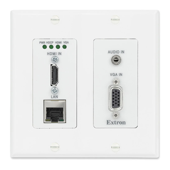
XTP T UWP 202 Rear (Left) and Front (Right) Panel Features (LAN Model)
Figure 1.
Installation
NOTE:
If using a junction box, use a metal box only.
•
Ensure the installation meets the building, electrical, and safety codes.
•
For additional mounting considerations, see the XTP T UWP 202
User Guide at www.extron.com. For metal junction boxes, refer to the
manufacturer for additional mounting instructions and considerations.
ATTENTION:
•
Do not mount multiple devices adjacent to each other in the
same metal junction box. Add at least a one gang space
between devices.
•
Ne procédez pas à une installation juxtaposée des appareils
dans le même boîtier de dérivation métallique. Veuillez
laisser un espace d'un gang minimum entre chaque
appareil.
Wall Mount Preparation
1.
Using a soft pencil, mark cut guidelines on the mounting surface. For
accuracy, use a template or the mounting enclosure.
NOTE:
Install junction boxes against a wall stud (see figure 2).
2.
Cut a hole in the wall. To avoid making the hole too big, cut inside the
marked lines.
3.
If using the mud ring in a wall with insulation inside, remove at least
6 inches of the insulation in all directions around the cutout. If a wall
stud interferes with removing the insulation, remove as much as
possible between the cutout and the wall stud.
4.
Test the fit by inserting the mud ring or metal junction box into the hole
in the wall. If necessary, enlarge the hole as needed.
5.
Install the UL Listed junction box or mud ring.
•
UL Listed metal junction box — Use mounting screws to fasten
the box to a wall stud (see figure 2).
Mud ring — Attach the mounting screws to the mud ring and
•
loosely attach backing clips to the ends of the screws (see
figure 3). Fit the mud ring in the opening and then rotate the
backing clips until they fit snugly against the back of the wall.
Power Connection,
Reset Button, and
Input Connections
F
DC power connector
Reset button
G
H
HDMI input
connector
Analog audio input
I
connector
J
Female 15-pin HD
connector
Rear
B C F
Tx
Rx
G
Tx Rx
Tx Rx G
RS-232
IR
RS-232
POWER
12V
OVER XTP
REMOTE
1.0 A MAX.
XTP T UWP 202
XTP OUT
A
Screws or
Nails
Wall opening is
flush with edge
of box.
Cable
Clamp
Signal Output
Cable
Figure 2.
Backing Clip
Mounting Screw
Rotate the backing clip
out of the way to insert
the mud ring into the wall.
Figure 3.
H
G
I
PWR HDCP HDMI
VGA
RESET
AUDIO IN
HDMI IN
AUDIO
CLIP
VGA IN
AUTO
SWITCH
LAN
CONFIG
Front
D
E
J
Wall Stud
IN
D IO
A U
S E
T
R E
VG A
M I
H D
D IO
P
A U
A IN
D C
IP
V G
R H
C L
PW
M I
IN
H D
T O
A U
IT C
H
S W
N F
IG
C O
L A N
XTP T UWP 202
Decorator-Style Faceplate
Metal Junction Box Installation
IN
D IO
A U
T
S E
R E
VG A
M I
H D
D IO
P
A U
A IN
D C
IP
V G
R H
C L
PW
IN
M I
H D
T O
A U
IT C
H
S W
N F
IG
C O
L A N
XTP T UWP 202
Decorator-Style Faceplate
Mud Ring Installation
1
Advertisement
Table of Contents

Related Manuals for Extron electronics XTP T UWP 202


Summary of Contents for Extron electronics XTP T UWP 202
- Page 1 XTP T UWP 202 • Setup Guide The XTP T UWP 202 is a two-input XTP decorator-style wallplate transmitter that can be installed into the provided mud ring or a UL Listed metal junction box. This guide provides instructions for an experienced installer to install and connect the XTP T UWP 202.
-
Page 2: Rear Panel Connections
Connect the XTP T UWP 202 to an XTP matrix switcher and enable the remote power feature on the XTP matrix switcher. Device Installation Using the provided screws, attach the XTP T UWP 202 to the mud ring or metal junction box through the inner screw holes (see figure 2 or...
Need help?
Do you have a question about the XTP T UWP 202 and is the answer not in the manual?
Questions and answers