Extron electronics DTP T USW 233 Setup Manual
Three input switcher with integrated dtp transmitter and audio embedding
Hide thumbs
Also See for DTP T USW 233:
- Setup manual (4 pages) ,
- User manual (42 pages) ,
- User manual (39 pages)
Advertisement
Quick Links
DTP T USW 233 • Setup Guide
This guide provides instructions for an experienced installer to set up and operate the
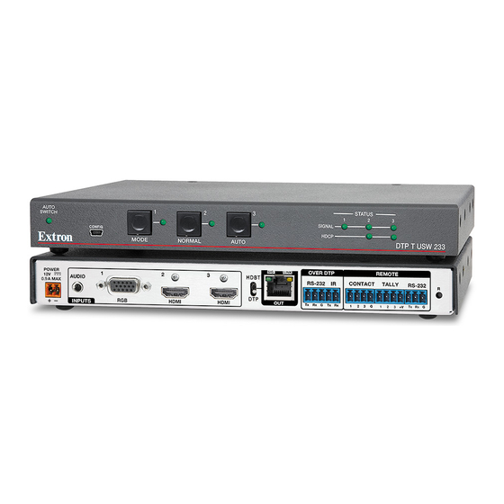
Extron DTP T USW 233 switching video transmitter. The DTP T USW 233 transmitter switches among
an analog video and two digital (HDMI) video inputs and, paired with a compatible receiver, can
extend the selected signal up to 230 feet (70 m). If the selected input is HDMI, the extended video
signal is HDCP-compliant.
POWER
1
12V
AUDIO
--A MAX
INPUTS
K K
D D
Installation
Step 1 — Mounting
Turn off or disconnect all equipment power sources and mount the transmitter as required.
Step 2 — Making Connections
Inputs
Input 1 (RGB) connector — Connect a VGA cable between this port and the VGA output port of the analog video source.
A
Input 2 and 3 (HDMI) connectors — Connect HDMI cables between these ports and the HDMI output ports of the digital video
B
sources.
LockIt
NOTE: See the
TP function switch —
C
If the receiving device is in the Extron DTP series, set this switch to DTP. The TP output consists of HDMI with embedded audio,
analog audio, RS-232 and IR, and remote power. The transmitter and receiver can be powered by one 12 VDC power supply
connected to either unit.
For an HDBaseT-enabled receiver type, set this switch to HDBT position. The TP output consists of HDMI with embedded audio plus
RS-232 and IR. The transmitter and receiver each requires its own 12 VDC power supply.
ATTENTION:
Position this switch BEFORE connecting the appropriate device to the TP connector. Failure to comply can damage the
•
endpoint.
•
Positionnez le sélecteur AVANT de connecter l'appareil approprié au connecteur TP. Ne pas respecter cette procédure
pourrait endommager le point de connexion.
Audio input — Connect an unbalanced stereo audio source to this 3.5 mm mini stereo jack for an analog audio input.
D
NOTE: Analog input audio is not embedded in the HDMI signal; it is transmitted separately and is present for any selected input.
Over DTP RS-232 and IR pass-through
RS-232 and IR connector — To pass serial or infrared data or control signals on the Over
E
DTP RJ-45 output, connect the controlling device to the transmitter via the RS-232 and IR
captive screw connector. Connect the device to be controlled to the receiver.
2
RGB
HDMI
A A
B B
Lacing Brackets
®
on page 3 of this guide to securely fasten the HDMI connectors to the transmitter.
SIG
LINK
3
HDBT
DTP
HDMI
DTP OUT
B B
C C
F F
OVER DTP
REMOTE
RS-232
IR
CONTACT
TALLY
Tx
Rx
G
Tx
Rx
1
2
3
G
1
2
3 + V
E E
G G
H H
RS-232
RESET
Tx
Rx
G
I I
J J
IR Device
Rx
Tx
Gnd
Tx
Rx
Gnd
RS-232 Device
1
Advertisement

Related Manuals for Extron electronics DTP T USW 233


Summary of Contents for Extron electronics DTP T USW 233
- Page 1 This guide provides instructions for an experienced installer to set up and operate the Extron DTP T USW 233 switching video transmitter. The DTP T USW 233 transmitter switches among an analog video and two digital (HDMI) video inputs and, paired with a compatible receiver, can extend the selected signal up to 230 feet (70 m).
- Page 2 Reset button — This button initiates two levels of reset. For different reset levels, use an RS-232 Device Extron Tweeker or small screwdriver to press and hold the recessed button while the switcher is running or while applying power. See the DTP T USW 233 User Guide, available at www.extron.com, for details. Power...
- Page 3 Operation Switching inputs Press the button. Select the desired input by pressing the associated input button. Observe that the The LED lights green. LED for the selected input lights. NOTE: The switcher must be in normal (manual) mode (see below). Selecting the switch mode MODE NORMAL...
- Page 4 Extron USA - West Extron USA - East +1.714.491.1500 +1.919.850.1000 +31.33.453.4040 +91.80.3055.3777 +1.714.491.1517 FAX +1.919.850.1001 FAX +31.33.453.4050 FAX +91.80.3055.3737 FAX 68-2490-50 www.extron.com © 2015 Extron Electronics All rights reserved. All trademarks mentioned are the property of their respective owners. Rev. C 11 15...
Need help?
Do you have a question about the DTP T USW 233 and is the answer not in the manual?
Questions and answers