Table of Contents
Advertisement
Quick Links
FOX T UWP 302 • Installation Guide
CLASS 1 LASER PRODUCT,
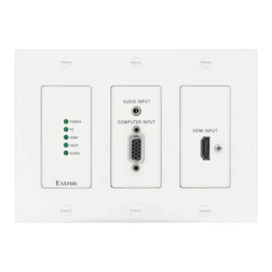
This guide provides instructions for an experienced installer to install and connect the 3-gang Extron FOX T UWP 302 Universal
Wallplate Transmitter and switcher. It can fit into a wall or floor box.
NOTE:
The FOX T UWP 302 is not compatible with the FOX 3G HD-SDI,
FOX 3G DVC, or FOX AV models.
WARNING:
Risk of serious physical injury. The transmitter outputs continuous
invisible light, which may be harmful to the eyes; use with caution.
•
Do not look into the fiber optic cable connectors or into the fiber optic cables
themselves.
•
Plug the attached dust caps into the optical transceivers when the fiber optic
cable is unplugged.
Planning
CAUTION:
Risk of personal injury. Failure to check these items may result in personal injury.
ATTENTION:
Failure to check the items listed below may result in property damage.
…
Check that the installation meets the building, electrical, and safety codes.
Installation
Step 1 — Preparing the Mounting Surface
Install a UL-listed electrical junction box according to the instructions of the manufacturer.
a.
Secure cables with clamps or ties to provide strain relief (see
b.
Trim back and insulate shields with heat shrink.
c.
ATTENTION:
To prevent short circuits, the outer foil shield can be cut back to the point where the cable exits the cable
clamp. Both braided and foil shields should be connected to an equipment ground at the other end of the cable.
Step 2 — Making Rear Panel Connections
Fiber optic connector — Connect a fiber cable between the Tx port on the FOX T UWP 302
A
and the Rx port on a receiver.
To return serial data from the receiver to the FOX T UWP 302, connect a fiber cable between
the Rx port on the transmitter and the Tx port on the receiver.
Remote RS-232 and Alarm connector — For serial RS-232 control of the FOX T UWP 302,
B
connect the host device to the leftmost poles (Tx, Rx, and G) of this 5-pole captive screw
connector. For remote monitoring of the status of fiber optic link 2, connect a custom
monitoring device to the rightmost poles (1 and 2) of this 5-pole captive screw connector.
Power connector — Connect the provided 12 VDC external power supply to this 3.5 mm,
C
2-pole captive screw connector.
Step 3 — Mounting
Attach the FOX T UWP 302 to the junction box with screws.
D
TIP:
If necessary, configure the device before attaching the
decorator-style faceplate in the step below (see
the next page or the FOX T UWP 302 User Guide for more details).
Attach the decorator-style faceplate to the FOX T UWP 302 with the provided
E
screws.
see FOX T UWP 302 User Guide at
.
www.extron.com
Making Rear Panel Connections
Flush with
Wall Surface
on
Mounting
Screws
(6 Plcs)
E E E E
E E E E
E E
Product Category
AUDIO INPUT
POWER
COMPUTER INPUT
PC
HDMI INPUT
HDMI
HDCP
AUDIO
below for necessary cables).
A A A A
A A A A
A A
B B
B B B B
B B B B
C C C C
C C C C
C C
Rear Panel Connectors from the Side View
Wall Stud
Wall Box
Screws or Nails
D D
D D D D
D D D D
1
Advertisement
Table of Contents

Related Manuals for Extron electronics FOX T UWP 302


Summary of Contents for Extron electronics FOX T UWP 302
- Page 1 FOX T UWP 302 User Guide at This guide provides instructions for an experienced installer to install and connect the 3-gang Extron FOX T UWP 302 Universal Wallplate Transmitter and switcher. It can fit into a wall or floor box.
-
Page 2: Remote Control
CONFIG config port for serial control of the FOX T UWP 302. Use SIS commands or install the FOX Extenders Control Program from the Extron Software Products DVD or check the Extron website, www.extron.com, for the latest version (see the FOX T UWP 302 User Guide for remote control details).
Need help?
Do you have a question about the FOX T UWP 302 and is the answer not in the manual?
Questions and answers