
Related Manuals for Extron electronics DTP T UWP 4K 232 D


Summary of Contents for Extron electronics DTP T UWP 4K 232 D
- Page 1 User Guide HDMI Transmitters DTP T UWP 4K D Series HDMI Twisted Pair Extender Transmitters 68-3157-01 Rev. A 12 17...
-
Page 2: Safety Instructions
Safety Instructions Safety Instructions • English Istruzioni di sicurezza • Italiano WARNING: This symbol, , when used on the product, is intended to AVVISO: Questo simbolo, ,quando viene utilizzato il prodotto, serve alert the user of the presence of uninsulated dangerous voltage within ad avvisare l’utente della presenza di tensioni pericolose non isolate the product’s enclosure that may present a risk of electric shock. - Page 3 安全記事 • 繁體中文 안전 지침 • 한국어 警 告 경고: 이 기호 가 제품에 사용될 경우, 제품의 인클로저 내에 있는 若產品 上使 用此 符 號 , 是 為了提 醒 使 用者,產品 機 殼內 存 在 著 접지되지 않은 위험한 전류로 인해 사용자가 감전될 위험이 있음을 可能會導致觸電之風險的未絕緣危險電壓。...
- Page 4 RGB Systems, Inc. or ® (SM) (TM) Extron Electronics (see the current list of trademarks on the Terms of Use page at www.extron.com): Registered Trademarks (®) Extron, Cable Cubby, ControlScript, CrossPoint, DTP, eBUS, EDID Manager, EDID Minder, Flat Field, FlexOS, Global Configurator, Global Scripter, GlobalViewer, Hideaway, HyperLane, IP Intercom, IP Link, Key Minder, LinkLicense, LockIt, MediaLink, MediaPort, NetPA,...
- Page 5 Conventions Used in this Guide Notifications The following notifications are used in this guide: CAUTION: Risk of minor personal injury. ATTENTION : Risque de blessure mineure. ATTENTION: • Risk of property damage. • Risque de dommages matériels. NOTE: A note draws attention to important information. Software Commands Commands are written in the fonts shown here: ^AR Merge Scene,,Op1 scene 1,1 ^B 51 ^W^C...
- Page 6 Contents Introduction Remote Control ............1 ........... 13 About this Guide ..........1 Contact Closure Control ........13 About the DTP T UWP 4K D Extenders ....1 Simple Instruction Set Control ......13 Twisted Pair Cable Advantages ....... 2 Host-to-Extender Communications ....
-
Page 8: About This Guide
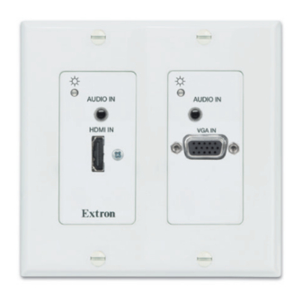
About the and DTP T UWP 4K D Extenders The Extron DTP T UWP 4K 232 D and DTP T UWP 4K 332 D extenders are a series of HDMI and VGA transmitters (see figure 1) that are housed in enclosures that can be mounted in Underwriters Laboratories (UL) standard wall boxes with decorator-style faceplates. -
Page 9: Twisted Pair Cable Advantages
• DTP T UWP 4K 232 D transmitters can transmit 720p, 1080i or 1080p HDTV video, and 4K signals up to 230 feet (70 meters) over STP cable. •... -
Page 10: Mounting The Transmitter
Installation and Operation This section describes the installation and the operation of the extenders, including: • Mounting the Transmitter • DTP T UWP 4K D Connections Twisted Pair Recommendations for DTP Communication • • Power Supply Wiring • RS-232 Connector Wiring •... -
Page 11: Site Preparation And Wall Box Installation
Site Preparation and Wall Box Installation Choose a location that allows cable runs without interference. Allow enough depth for both the wall box and the cables. Install the cables into the wall, furniture, or conduits before installing the wallplate. NOTE: The extender units are very deep and have connectors on the back side. Extron recommends a 2-gang wall box that has a depth of at least 3.0 inches (7.6 cm) to accommodate the connectors and cables. -
Page 12: Mud Ring Installation
Feed the twisted pair cables and, if applicable, the power cables through the opening and through the wall box punch-out holes, securing them with cable clamps to provide strain relief. NOTES: • In order to fit in the wall box, the twisted pair cables and RJ-45 connectors should not have a boot installed. -
Page 13: Final Installation
Final Installation After testing and making any adjustments, do the following: At the power outlet, unplug the power supply. NOTE: One power supply can power both the transmitter and the receiver (see Power Supply Wiring on page 9). Mount the transmitter into the wall box or mud ring and attach the supplied decorator-style faceplate to the unit (see figure 2 on page 4). -
Page 14: Rear Panel
Rear Panel Reset DTP T HWP/UWP 232/332 D Figure 5. DTP T UWP 4K D Rear Panel Connectors Rear Panel DC power input connector — Plug the included external 12 VDC power supply into Power Supply Wiring either this 2-pole connector (see on page 9 to wire the power connector) or the power input connector on the receiver (see the user guide of your receiver for more information). -
Page 15: Twisted Pair Recommendations For Dtp Communication
Twisted Pair Recommendations for DTP Communication Use the following pin configurations for both ends of the shielded twisted pair cables. Pins: TIA/EIA 12345678 T568-B Wire color White-orange Orange White-green Blue White-blue Green White-brown Brown TP Wires Figure 6. Twisted Pair Cable Configuration Supported Cables The extenders are compatible with shielded twisted pair cable (F/UTP, SF/UTP, and S/FTP). -
Page 16: Power Supply Wiring
Power Supply Wiring NOTES: • Only one power supply is required for both the transmitter and receiver. A single power supply connected to either unit in the pair powers both units. • A power supply is included with each individually-packaged transmitter. •... -
Page 17: Rs-232 Connector Wiring
• Power supply voltage polarity is critical. Incorrect voltage polarity can damage the power supply and the unit. The ridges on the side of the cord (see figure 7 on previous page) identify the power cord negative lead. • La polarité de la source d’alimentation est primordiale. Une polarité incorrecte pourrait endommager la source d’alimentation et l’unité. -
Page 18: Transmitter Leds
Operation AUTO SW AUTO SW AUDIO IN AUDIO IN AUDIO IN AUDIO IN HDCP HDCP VGA IN HDMI IN HDMI IN HDMI IN CONFIG CONFIG IR OUT DTP T HWP 232/332 D DTP T UWP 4K D Front Panel Front Panel Figure 10. -
Page 19: System Operation
System Operation After the transmitter, the receiver, and their connected devices are powered up, the system is fully operational. If any problems are encountered, ensure all cables are routed and connected properly. NOTES: • Ensure that the video source and display are properly connected to the transmitter and receiver pair, and that the transmitter, the receiver, and the display have power applied before power is applied to the video source. -
Page 20: Remote Control
Examples of the extender-initiated messages are listed below: © Copyright 20yy Extron Electronics DTP T UWP 4K 232 D nnnn Extron DTP T UWP 4K D Series • Remote Control... -
Page 21: Error Responses
The extender issues the copyright message when it first powers on. is the firmware version number and is the part number. nnnn All ] The extender also sends the In message whenever the selected input is changed. is the input number. A in the field indicates no input is selected. -
Page 22: Symbol Definitions
Symbol definitions = Carriage return/line feed = Carriage return (no line feed) = Pipe (can be used interchangeably with the character) • = Space = Escape key = Can be used interchangeably with the character = Input number 0 through 2 (0 = deselect input [break tie]. This results in the output being disabled.) = HDMI, 2 = VGA = Auto switch mode = disabled (default) -
Page 23: Command And Response Table For Sis Commands
Command and Response Table for SIS Commands Command Function SIS Command Response Additional Description (Host to Unit) (Unit to Host) Auto Switch mode Disable Manual input switching Ausw0 0AUSW Priority to highest active input Gives priority to the highest numbered Ausw1 1AUSW active input (default) - Page 24 SIS Command Response Additional Description Command Function (Host to Unit) (Unit to Host) Select and view input Select an input •All Select input to transmit to the connected receiver Example: In01•All View input selection Signal status Request all signal statuses •...
- Page 25 SIS Command Response Additional Description Command Function (Host to Unit) (Unit to Host) Enable or Disable (mute) HDMI output embedded audio Enable HDMI audio mute Enable HDMI audio mute 1AFMT Afmt1 Disable HDMI audio mute Disable HDMI audio mute (default) 0AFMT Afmt0 View HDMI audio configuration...
- Page 26 SIS Command Response Additional Description Command Function (Host to Unit) (Unit to Host) Reset Reset to factory setting Reset to factory defaults ZXXX Information requests Information request • • • • Ausw X1$] View/Read EDID in HEX format Read data as text from the EDID assigned EDID and used on input X1^]...
-
Page 27: Reference Information
Reference Information This section provides information about configuring the DTP T UWP 4K D series and product wallplate dimensions. The following topics are discussed: Configuring the Transmitter with the Extron PCS Software Decorator-Style Wallplate Template Dimensions Configuring the Transmitter with the Extron PCS Software The Extron PCS software is used to configure and control the DTP T UWP 4K D series of transmitters. - Page 28 Using PCS with the DTP T UWP 4K D Transmitters To connect to the DTP T UWP 4K D transmitter, Connect a male USB Mini-B cable to the front panel USB port (see figure 4, on page 6) and to the PC with the PCS software installed.
- Page 29 • Disconnect — Disconnects the currently connected device and returns the software to the Device Discovery screen Hardware Settings — Opens the Hardware Settings window • • Reset Device... — Opens the Reset Device window to reset the device settings •...
- Page 30 • Color Bit Depth — Options include Auto (default) or Force 8-bit HDCP Status — Shows the HDCP status of the display connected to the receiver • • 5V Hot-Plug Mode — Options include Auto or Enabled (default) • HDMI Video Pass-Through Mode — Enabling this option sets the HDMI input to pass-through a 4K30 signal unaltered.
- Page 31 • Available EDID — Displays the library of available EDID located on the connected unit or the local PC Inputs — Displays the current EDID of the connected input • Image Settings NOTE: The image settings on this panel only apply to the RGB/VGA input (Input 2). Adjust the following settings by either typing the desired values into their respective fields, or using the up and down arrows next to each field.
-
Page 32: General Settings
HDMI Input • Auto (Embedded digital audio takes priority) Digital Audio • • Analog Audio VGA Input • No Embedding • Embedded Audio General Settings The General Settings tab contains Auto Switch settings and a button to access the Hardware Settings window. Auto Switch —... -
Page 33: Updating The Device Firmware
Use the Device Name tab of the Hardware Settings window to change the device name, if necessary. Updating the Device Firmware Update the device firmware via the Extron PCS software. Downloading device firmware To obtain the latest version of firmware for your distribution amplifier: www.extron.com , click the link at the top of the page (figure 11,... - Page 34 Open PCS. If there is no desktop icon, open the program from the Start menu by selecting: Start > All Programs > Extron Electronics > Extron Product Configuration Software> Product Configuration Software The Device Discovery screen opens with the connected transmitter shown in the device list.
- Page 35 Select the DTP T UWP 4K D product from the device list. The DTP T UWP 4K D module opens. From the drop-down device menu, select Update Firmware to this Device..The Update Firmware dialog box appears. Click Continue. The Update Firmware to this Device dialog box appears. Extron DTP T UWP 4K D Series •...
- Page 36 Click the Open Firmware File... button, browse to and select the desired firmware file. ATTENTION: • Valid firmware files must have the file extension S19. A file with any other extension is not a firmware upgrade for this device and could cause the device to stop functioning.
-
Page 37: Decorator-Style Wallplate Template Dimensions
Decorator-Style Wallplate Template Dimensions To create a template, use the dimensions shown on figure 12. NOTES: • The drawing is not full size or to scale. DO NOT scale up or print to use as a template. • Full size templates are available at www.extron.com. Template for the 2-gang mounting bracket 4.26"... - Page 38 Extron Electronics makes no further warranties either expressed or implied with respect to the product and its quality, performance, merchantability, or fitness for any particular use. In no event will Extron Electronics be liable for direct, indirect, or consequential damages resulting from any defect in this product even if Extron Electronics has been advised of such damage.
Need help?
Do you have a question about the DTP T UWP 4K 232 D and is the answer not in the manual?
Questions and answers