
Subscribe to Our Youtube Channel
Related Manuals for Extron electronics XTP T UWP 202 4K


Summary of Contents for Extron electronics XTP T UWP 202 4K
- Page 1 User Guide XTP Systems XTP T UWP 202 4K XTP Transmitter – Decorator-Style Wallplate 68-2729-01 Rev. A 05 19...
-
Page 2: Safety Instructions
Safety Instructions Safety Instructions • English Istruzioni di sicurezza • Italiano AVVERTENZA: Il simbolo, , se usato sul prodotto, serve ad avvertire WARNING This symbol, , when used on the product, is intended to l’utente della presenza di tensione non isolata pericolosa all’interno del alert the user of the presence of uninsulated dangerous voltage within the contenitore del prodotto che può... - Page 3 ついては、 エクス トロンのウェブサイ ト より 『Extron Safety www.extron.com and Regulatory Compliance Guide』 (P/N 68-290-01) をご覧ください。 Copyright © 2019 Extron Electronics. All rights reserved. www.extron.com Trademarks All trademarks mentioned in this guide are the properties of their respective owners. The following registered trademarks ( ®...
-
Page 4: Fcc Class A Notice
FCC Class A Notice This equipment has been tested and found to comply with the limits for a Class A digital device, pursuant to part 15 of the FCC rules. The Class A limits provide reasonable protection against harmful interference when the equipment is operated in a commercial environment. -
Page 5: Software Commands
Conventions Used in this Guide Notifications The following notifications are used in this guide: WARNING: Potential risk of severe injury or death. AVERTISSEMENT : Risque potentiel de blessure grave ou de mort. CAUTION: Risk of minor personal injury. ATTENTION : Risque de blessure mineure. ATTENTION: •... -
Page 6: Table Of Contents
UL Listed Metal Junction Box Installation ..7 Software Product Page ........27 Rear Panel Connectors ........8 Software Operation..........28 Mounting the XTP T UWP 202 4K ..... 10 Connections ..........28 Front Panel Connectors ........11 Menu Bar ............29 Connection Details .......... - Page 7 XTP T UWP 202 4K Wallplate Transmitter • Contents xiii...
-
Page 8: Introduction
XTP T UWP 202 4K Wallplate Transmitter as well as reference information. In this guide, the terms XTP T UWP 202 4K and “transmitter” are used interchangeably to refer to all models of the XTP T UWP 202 4K Wallplate Transmitter. -
Page 9: System Compatibility
The following diagram shows one way the XTP T UWP 202 4K can be integrated in an XTP point-to-point application. The transmitter can also be used with an XTP matrix switcher (see the XTP matrix switcher user guide for more details on matrix applications and configuration). -
Page 10: Features
Remote power capability — Allows the XTP T UWP 202 4K to be powered by an • XTP matrix switcher or XTP power injectors to simplify integration. -
Page 11: Installation
• • Connection Details Installation Overview The XTP T UWP 202 4K can be installed into the provided mud ring or a UL Listed metal electrical junction box. ATTENTION: • Do not mount multiple devices adjacent to each other in the same metal junction box. -
Page 12: Metal Junction Box Or Mud Ring Installation
Route and connect cables to the rear panel connectors (see Rear Panel Connectors on page 8). Mount the XTP T UWP 202 4K to the mud ring or metal junction box (see Mounting the XTP T UWP 202 4K on page 10). -
Page 13: Mud Ring Installation
Backing Clip 0.75" #6-32 Screw 1.25" #6-32 Screw Layout A Layout B Figure 3. Backing Clip Installation Use a cross-head (Phillips) screwdriver to fasten the screws and backing clips in place. XTP T UWP 202 4K Wallplate Transmitter • Installation... -
Page 14: Ul Listed Metal Junction Box Installation
Le blindage tressé et le blindage en aluminium devraient être connectés à la masse d’un équipement à l’autre bout du câble. XTP T UWP 202 4K Wallplate Transmitter • Installation... -
Page 15: Rear Panel Connectors
Rear Panel Connectors XTP output connector — Connect a twisted pair cable to the RJ-45 connector labeled “XTP OUT” on the XTP T UWP 202 4K and the XTP input port on another XTP device to pass all signals (see TP Cable Termination and Recommendations page 13). - Page 16 Confirm the polarity of the power supply wires. For wiring considerations, see Power Connection on page 16. NOTE: The XTP T UWP 202 4K can also be powered remotely (see Remote power on page 17). XTP T UWP 202 4K Wallplate Transmitter • Installation...
-
Page 17: Mounting The Xtp T Uwp 202 4K
Installing the XTP T UWP 202 4K (LAN Model Shown) in a Metal Junction Box Align the mounting screws on the XTP T UWP 202 4K with the available holes on the mud ring (see figure 7, ) or metal junction box (see figure 8,... -
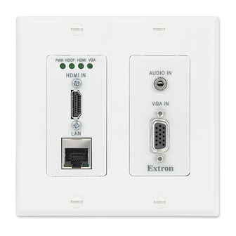
Page 18: Front Panel Connectors
Tip (L) XTP connection when a specific audio format is not specified. Ring (R) Sleeve ( ) 3.5 mm Stereo Plug Connector (unbalanced) XTP T UWP 202 4K Wallplate Transmitter • Installation... -
Page 19: Connection Details
ATTENTION: • Connect and pull the tie wraps until they are secure. Do not overtighten. • Connectez et tirez les serre-câbles jusqu’à ce qu’ils soient sécurisés. Ne pas trop serrer. XTP T UWP 202 4K Wallplate Transmitter • Installation... -
Page 20: Tp Cable Termination And Recommendations
RJ-45 Connector Figure 12. TP Cable Termination Supported cables The XTP T UWP 202 4K is compatible with shielded twisted pair (F/UTP, SF/UTP, and S/FTP) cable. ATTENTION: • Do not use Extron UTP23SF-4 Enhanced Skew-Free AV UTP cable or STP201 cable to link the XTP products. -
Page 21: Cable Recommendations
Do not comb the cable for the first 20 meters, where cables are straightened, aligned, and secured in tight bundles. • Loosely place cables and limit the use of tie wraps or hook-and-loop fasteners. • Separate twisted pair cables from AC power cables. XTP T UWP 202 4K Wallplate Transmitter • Installation... -
Page 22: Rs-232 And Ir Over Xtp Communication
Output Cord Figure 14. Power Wiring The XTP T UWP 202 4K can be connected to a local power supply (see the notifications on the next page for local power considerations). XTP T UWP 202 4K Wallplate Transmitter • Installation... - Page 23 La longueur idéale est de 5 mm (3/16 inch). Do not tin the stripped power supply leads. Tinned wires are not as secure in the TIP: captive screw connectors and could be pulled out. XTP T UWP 202 4K Wallplate Transmitter • Installation...
-
Page 24: Remote Power
Aucune partie du réseau qui utilise l’alimentation XTP à distance ne peut être routée en extérieur. Power injector To power the XTP T UWP 202 4K remotely with an XTP Power Injector, power one device locally (see Local power on page 15) and connect an XTP Power Injector to the XTP cable run along the XTP ports (see the XTP Power Injector User Guide at www.extron.com... -
Page 25: Operation
Operation This section contains information for front panel operation and configuration of the XTP T UWP 202 4K. Topics in this section include: • Front Panel Features • EDID Reset Mode • After all transmitters, all receivers, and other related devices are connected and powered, the system is fully operational. -
Page 26: Edid
EDID To manage EDID on the XTP T UWP 202 4K, use the XTP System Configuration Software (see EDID Minder on page 38). The XTP T UWP 202 4K can record and save EDID in a user memory location, select a pre-defined EDID, or use EDID from a display connected to a receiver. -
Page 27: Sis Configuration And Control
SIS commands consist of one or more characters per field. No special characters are required to begin or end a command sequence. When the XTP T UWP 202 4K determines that a command is valid, it executes the command and sends a response to the host device. All responses from the transmitter to the host end with a carriage return and a line feed (CR/LF = ), which signals the end of the response character string. -
Page 28: Error Responses
Error Responses When the XTP T UWP 202 4K receives an SIS command and determines that it is valid, it performs the command and sends the corresponding response to the host device. If the command is determined invalid or contains invalid parameters, the transmitter returns an error response to the host. -
Page 29: Command And Response Tables For Sis Commands
1 dB increments ( = default) X& = Audio level = 720p @ 50 Hz = Black video signal resolution = 720p @ 60 Hz (default) = 1080p @ 60 Hz XTP T UWP 202 4K Wallplate Transmitter • SIS Configuration and Control... -
Page 30: Picture Adjustment Commands (Analog Only)
KEY: = off or disable = Enable or disable = on or enable (default) 0-255 = Pixel phase = default) 0-65535 32768 = Horizontal or vertical shift XTP T UWP 202 4K Wallplate Transmitter • SIS Configuration and Control... -
Page 31: Preset Commands
= enabled (default) = Preset number = disable (default) = Color bar test pattern = 720p @ 50 Hz = 720p @ 60 Hz = 1080p @ 60 Hz XTP T UWP 202 4K Wallplate Transmitter • SIS Configuration and Control... - Page 32 = video or TMDS not detected = Signal presence = video or TMDS detected = no source = HDCP status = HDCP compliant source = non-HDCP compliant source XTP T UWP 202 4K Wallplate Transmitter • SIS Configuration and Control...
-
Page 33: Xtp System Configuration Software
XTP System Configuration Software This section contains installation and configuration procedures for the XTP System Configuration Software for configuring and controlling the XTP T UWP 202 4K. Topics in this section include: Software Installation • • Software Operation Software Installation The XTP System Configuration Software is available for download on the Extron website, www.extron.com. -
Page 34: Software Product Page
Submit any required information to start the download. Note where the file is saved. Open the saved executable (.exe) file. Follow the instructions that appear on the screen to install the program. XTP T UWP 202 4K Wallplate Transmitter • XTP System Configuration Software... -
Page 35: Software Operation
Software Operation The XTP T UWP 202 4K can be controlled directly from the rear panel configuration port (see figure on page 11) or remotely from an XTP matrix switcher. Connections The XTP System Configuration Software opens to the screen. This screen is Connections used to establish communication with an XTP device through USB connection. -
Page 36: Menu Bar
Backup and Restore Commissioning Report available when directly connected to the XTP T UWP 202 4K. See an XTP matrix switcher user guide (www.extron.com) for more information on these features. XTP T UWP 202 4K Wallplate Transmitter • XTP System Configuration Software... -
Page 37: Update Firmware
From the menu, select . The Tools Software Preference Software Preference dialog box opens. Figure 27. Software Preference Dialog Box Click the button. The dialog box closes. Reset XTP T UWP 202 4K Wallplate Transmitter • XTP System Configuration Software... -
Page 38: About The Software
This option opens the XTP System Configuration Software help file in a Web browser. From the menu, select Help Help Extron Website This option opens the Extron website in a Web browser. From the menu, select Help Extron Website XTP T UWP 202 4K Wallplate Transmitter • XTP System Configuration Software... -
Page 39: Device Settings
NOTE: The signal indicators on the AV input buttons display green when a signal is present on the corresponding input or gray when there is no signal present. XTP T UWP 202 4K Wallplate Transmitter • XTP System Configuration Software... -
Page 40: Input/Output Tab
HDCP authorized device. If the box is not checked, the source is blocked from encrypting its output. This may result in some content not being passed by the source device. NOTE: HDCP authorization is for the HDMI input only. XTP T UWP 202 4K Wallplate Transmitter • XTP System Configuration Software... -
Page 41: Analog Video Tab
Save Preset — To save a preset, select one from the list of presets and click the Save button. Preset Recall Preset — To recall a saved preset, select the desired preset from the list of presets and click the button. Recall Preset XTP T UWP 202 4K Wallplate Transmitter • XTP System Configuration Software... -
Page 42: Audio Tab
By default, the check box is not selected. If selected, also select the black video signal resolution from the Signal Type drop-down list. The default resolution is 720p @ 60 Hz. XTP T UWP 202 4K Wallplate Transmitter • XTP System Configuration Software... -
Page 43: General Tab
Factory Reset settings except for firmware. NOTE: This is the same as the SIS command (see the Reset mode ZXXX command on page 25). XTP T UWP 202 4K Wallplate Transmitter • XTP System Configuration Software... - Page 44 Audio Only — Displays whether the black video signal for audio-only transmission is enabled. Analog Audio Gain — Displays the analog audio gain in dB. XTP T UWP 202 4K Wallplate Transmitter • XTP System Configuration Software...
-
Page 45: Edid Minder
To assign EDID to all inputs: Select an available EDID icon from the , or Favorites Connected Outputs Available panel ( EDID Click the button ( Assign to All XTP T UWP 202 4K Wallplate Transmitter • XTP System Configuration Software... - Page 46 Common Timings Connected Outputs listing the EDID settings common among the selected outputs. Select the desired common EDID. The EDID is shown in the panel. Available EDID XTP T UWP 202 4K Wallplate Transmitter • XTP System Configuration Software...
-
Page 47: Reference Information
FOR WALL MOUNT Top Panel Figure 37. Mounting Template for 2-Gang Mud Rings (Not to Full Scale) Please measure the printed template before cutting. NOTE: Measure the template before cutting. XTP T UWP 202 4K Wallplate Transmitter • Reference Information... -
Page 48: Extron Warranty
Extron Electronics makes no further warranties either expressed or implied with respect to the product and its quality, performance, merchantability, or fitness for any particular use. In no event will Extron Electronics be liable for direct, indirect, or consequential damages resulting from any defect in this product even if Extron Electronics has been advised of such damage.
Need help?
Do you have a question about the XTP T UWP 202 4K and is the answer not in the manual?
Questions and answers