
Related Manuals for Dell PowerEdge R740xd


Summary of Contents for Dell PowerEdge R740xd
- Page 1 Dell EMC PowerEdge R740xd Installation and Service Manual Regulatory Model: E38S Series Regulatory Type: E38S001...
- Page 2 A WARNING indicates a potential for property damage, personal injury, or death. Copyright © 2017 Dell Inc. or its subsidiaries. All rights reserved. Dell, EMC, and other trademarks are trademarks of Dell Inc. or its subsidiaries. Other trademarks may be trademarks of their respective owners.
-
Page 3: Table Of Contents
Contents 1 PowerEdge R740xd system overview......................8 Supported configurations..............................8 Front view of the system..............................10 Left control panel view............................... 11 Right control panel view............................14 Back view of the system..............................15 NIC indicator codes..............................17 Power supply unit indicator codes..........................17 Drive indicator codes................................19... - Page 4 System Setup................................... 40 Viewing System Setup............................... 41 System Setup details..............................41 System BIOS................................42 iDRAC Settings utility..............................61 Device Settings................................62 Dell Lifecycle Controller..............................62 Embedded system management..........................62 Boot Manager...................................62 Viewing Boot Manager..............................62 Boot Manager main menu............................63 One-shot BIOS boot menu............................63 System Utilities................................63...
- Page 5 Removing a cooling fan............................. 79 Installing a cooling fan............................... 80 Intrusion switch................................80 Removing an intrusion switch........................... 81 Installing an intrusion switch............................81 NVDIMM-N battery................................. 82 Removing the NVDIMM-N battery from the air shroud..................82 Installing NVDIMM-N battery into air shroud......................83 Removing NVDIMM-N battery from mid drive tray....................
- Page 6 Removing the processor from the processor and heat sink module..............118 Installing the processor into a processor and heat sink module................. 120 Installing a processor and heat sink module......................122 Expansion cards and expansion card risers......................... 124 Expansion card installation guidelines........................124 Opening and closing the PCIe card holder latch....................128 Removing the expansion card from expansion card riser..................129 Installing expansion card into expansion card riser....................132...
- Page 7 7 Using system diagnostics...........................202 Dell Embedded System Diagnostics..........................202 Running the Embedded System Diagnostics from Boot Manager..............202 Running the Embedded System Diagnostics from the Dell Lifecycle Controller..........202 System diagnostic controls.............................203 8 Jumpers and connectors ...........................204 System board jumpers and connectors........................205 System board jumper settings............................207...
-
Page 8: Poweredge R740Xd System Overview
PowerEdge R740xd system overview The PowerEdge R740xd is a 2U rack server that supports up to: • Two Intel Xeon Processor Scalable Family processors • 24 DIMM slots supporting up to 1536 GB of memory • Two AC or DC power supply units •... - Page 9 Figure 1. Supported configurations PowerEdge R740xd system overview...
-
Page 10: Front View Of The System
The Information Tag is a slide-out label panel that contains system Information tag information such as Service Tag, NIC, MAC address, and so on. If you have opted for the secure default access to iDRAC, the Information tag also contains the iDRAC secure default password. PowerEdge R740xd system overview... -
Page 11: Left Control Panel View
BIOS, and networking parameters. You can also launch the virtual Keyboard, Video, and Mouse (KVM) viewer and virtual Kernel based Virtual Machine (KVM), on a supported mobile device. For more information, see the Integrated Dell Remote Access Controller User's Guide at Dell.com/idracmanuals. Related link... - Page 12 Expansion card installation guidelines System health and system ID indicator codes The system health and system ID indicator is located on the left control panel of your system. Figure 5. System health and system ID indicators PowerEdge R740xd system overview...
- Page 13 Indicates that the system is experiencing a fault. Check the System Event Log or the LCD panel, if available on the bezel, for specific error message. For more information about error messages, see the Dell Event and Error Messages Reference Guide at Dell.com/ openmanagemanuals >...
-
Page 14: Right Control Panel View
The iDRAC Direct port is micro USB 2.0-compliant. This port enables iDRAC Direct port you to access the iDRAC Direct features. For more information, see the iDRAC User’s Guide at Dell.com/idracmanuals. iDRAC Direct LED The iDRAC Direct LED indicator lights up to indicate that the iDRAC Direct port is connected. -
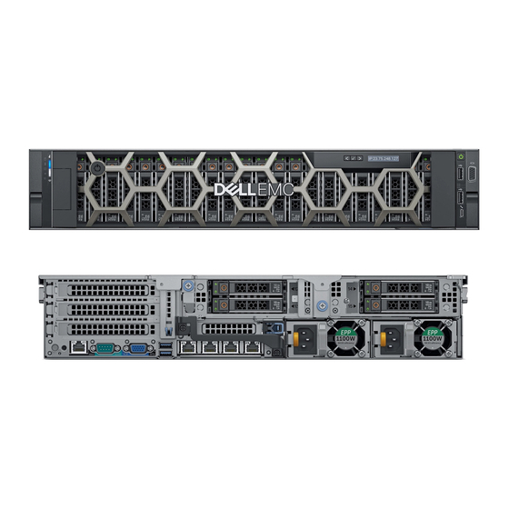
Page 15: Back View Of The System
Indicates that the laptop or tablet connected is recognized. seconds and off for two seconds) Turns off Indicates that the laptop or tablet is unplugged. Back view of the system Figure 8. Back view of 4 x 2.5 inch drive system PowerEdge R740xd system overview... - Page 16 Technical specifications section. Enables you to remotely access iDRAC. For more information, see the iDRAC9 dedicated port iDRAC User’s Guide at Dell.com/idracmanuals. The System Identification (ID) button is available on the front and back of System identification button the systems.
-
Page 17: Nic Indicator Codes
AC power supply units (PSUs) have an illuminated translucent handle that serves as an indicator and DC PSUs have an LED that serves as an indicator. The indicator shows whether power is present or a power fault has occurred. Figure 11. AC PSU status indicator AC PSU status indicator/handle PowerEdge R740xd system overview... - Page 18 If two PSUs are used, they must be of the same type and have the same maximum output power. CAUTION: Combining AC and DC PSUs is not supported and triggers a mismatch. Figure 12. DC PSU status indicator DC PSU status indicator PowerEdge R740xd system overview...
-
Page 19: Drive Indicator Codes
The activity LED indicator indicates whether the drive is currently in use or not. The status LED indicator indicates the power condition of the drive. Figure 13. Drive indicators on the drive and the mid drive tray backplane drive activity LED indicator drive status LED indicator drive backplane on mid drive tray drive PowerEdge R740xd system overview... -
Page 20: Lcd Panel
The LCD panel can be used to configure or view the system’s iDRAC IP address. For more information about error messages, see the Dell Event and Error Messages Reference Guide at Dell.com/openmanagemanuals > OpenManage software. The LCD panel is available only on the optional LCD bezel. The optional LCD bezel is hot pluggable. -
Page 21: Viewing Home Screen
LCD message with an SEL entry. Select Simple to view LCD error messages in a simplified user-friendly description. For more information about error messages, see the Dell Event and Error Messages Reference Guide at Dell.com/openmanagemanuals > OpenManage software. -
Page 22: View Menu
Express Service Code and Service Tag. Alternatively, the information may be on a sticker on the chassis of the system. The mini Enterprise Service Tag (EST) is found on the back of the system. This information is used by Dell to route support calls to the appropriate personnel. -
Page 23: Documentation Resources
Managing your system For information about systems management Dell.com/openmanagemanuals software offered by Dell, see the Dell OpenManage Systems Management Overview Guide. For information about setting up, using, and Dell.com/openmanagemanuals troubleshooting OpenManage, see the Dell OpenManage Server Administrator User’s Guide. - Page 24 Working with the Dell For information about understanding the features Dell.com/storagecontrollermanuals PowerEdge RAID controllers of the Dell PowerEdge RAID controllers (PERC), Software RAID controllers, or BOSS card and deploying the cards, see the Storage controller documentation. Understanding event and error For information about checking the event and error Dell.com/openmanagemanuals...
-
Page 25: Technical Specifications
Technical specifications The technical and environmental specifications of your system are outlined in this section. Topics: • System dimensions • Chassis weight • Processor specifications • PSU specifications • System battery specifications • Expansion bus specifications • Memory specifications • Storage controller specifications •... -
Page 26: Chassis Weight
Figure 16. System dimensions of PowerEdge R740xd system Table 15. Dimensions System Za (with Za (without bezel) bezel) PowerEdge R740xd 482.0 mm 434.0 mm 86.8 mm 35.84 mm 22.0 mm 678.8 mm 715.5 mm (3.42 inches) (26.72 (28.17 inches) (18.98 (17.09 inches) -
Page 27: Processor Specifications
Processor specifications The PowerEdge R740xd system supports up to two Intel Xeon Processor Scalable Family processors. PSU specifications The PowerEdge R740xd system supports up to two AC or DC power supply units (PSUs). Table 17. PSU specifications Class Heat dissipation... -
Page 28: System Battery Specifications
Expansion bus specifications The PowerEdge R740xd system supports up to eight PCI express (PCIe) generation 3 expansion cards that can be installed on the system board using expansion card risers. The following table provides detailed information about the expansion card riser specifications: Table 18. -
Page 29: Memory Specifications
Memory specifications The PowerEdge R740xd system supports up to twenty four 288-pins RDIMMS, LRDIMMS and NVDIMM-Ns with speeds of 2666 MT/s, 2400 MT/s and 2133 MT/s with support for memory optimized operation. Table 19. Memory specifications... -
Page 30: Storage Controller Specifications
External storage controller cards: PERC H840 and 12Gbps SAS HBA. Drive specifications Drives The PowerEdge R740XD system supports SAS, SATA, Nearline SAS hard drives/SSDs, or NVMe drives. Table 20. Supported drive options for the PowerEdge R740XD system 12 drives system Up to 12 3.5 inch (SAS, SATA or Nearline SAS) front accessible drives in slots 0 to 11... -
Page 31: Nic Ports
You can install up to eight PCIe add-on NIC cards. VGA ports The Video Graphic Array (VGA) port enables you to connect the system to a VGA display. The PowerEdge R740xd system supports two 15-pin VGA ports on the front and back panels. -
Page 32: Environmental Specifications
8, 16, 32 NOTE: 1920 x 1080 and 1920 x 1200 resolutions are only supported in reduced blanking mode. Environmental specifications NOTE: For additional information about environmental measurements for specific system configurations, see Dell.com/ environmental_datasheets. Table 22. Temperature specifications Temperature Specifications Storage –40°C to 65°C (–40°F to 149°F) -
Page 33: Standard Operating Temperature
Table 25. Maximum shock specifications Maximum shock Specifications Operating Six consecutively executed shock pulses in the positive and negative x, y, and z axes of 6 G for up to 11 ms. Storage Six consecutively executed shock pulses in the positive and negative x, y, and z axes (one pulse on each side of the system) of 71 G for up to 2 ms. - Page 34 150 W/8 core, 165 W/12 core and higher wattage processor [Thermal Design Power (TDP)>165 W] are not supported. • Redundant power supply unit is required. • Non-Dell qualified peripheral cards and/or peripheral cards greater than 25 W are not supported. • PCIe SSD is not supported. •...
-
Page 35: Particulate And Gaseous Contamination Specifications
Configuration Number of Heatsink Processor/DIMM DIMM Type of air processors blank blanks shroud PowerEdge One 1U high performance Required Required Not required Six high R740xd with heat sink performance mid bay fans PowerEdge Two 1U high performance Not required Required Not required Six high R740xd with... - Page 36 Table 32. Particulate contamination specifications Particulate contamination Specifications Air filtration Data center air filtration as defined by ISO Class 8 per ISO 14644-1 with a 95% upper confidence limit. NOTE: The ISO Class 8 condition applies to data center environments only. This air filtration requirement does not apply to IT equipment designed to be used outside a data center, in environments such as an office or factory floor.
-
Page 37: Initial System Setup And Configuration
The Integrated Dell Remote Access Controller (iDRAC) is designed to make system administrators more productive and improve the overall availability of Dell systems. iDRAC alerts administrators to system issues, helps them perform remote system management, and reduces the need for physical access to the system. -
Page 38: Log In To Idrac
Ensure that you change the default user name and password after setting up the iDRAC IP address. For more information about logging in to the iDRAC and iDRAC licenses, see the latest Integrated Dell Remote Access Controller User's Guide at Dell.com/idracmanuals. -
Page 39: Methods To Download Firmware And Drivers
Using Dell OpenManage Deployment Toolkit (DTK) Dell.com/openmanagemanuals Downloading drivers and firmware Dell recommends that you download and install the latest BIOS, drivers, and systems management firmware on your system. Prerequisite Ensure that you clear the web browser cache before downloading the drivers and firmware. -
Page 40: Pre-Operating System Management Applications
You can manage basic settings and features of a system without booting to the operating system by using the system firmware. Topics: • Options to manage the pre-operating system applications • System Setup • Dell Lifecycle Controller • Boot Manager • PXE boot Options to manage the pre-operating system applications Your system has the following options to manage the pre-operating system applications: •... -
Page 41: Viewing System Setup
The iDRAC settings utility is an interface to set up and configure the iDRAC parameters by using UEFI (Unified Extensible Firmware Interface). You can enable or disable various iDRAC parameters by using the iDRAC settings utility. For more information about this utility, see Integrated Dell Remote Access Controller User’s Guide at Dell.com/idracmanuals. -
Page 42: System Bios
System BIOS You can use the System BIOS screen to edit specific functions such as boot order, system password, setup password, set the SATA and PCIe NVMe RAID mode, and enable or disable USB ports. Related link System BIOS Settings details Boot Settings Network Settings System Information... -
Page 43: System Information
Option Description Network Settings Specifies options to manage the UEFI network settings and boot protocols. Legacy network settings are managed from the Device Settings menu. Integrated Devices Specifies options to manage integrated device controllers and ports, specifies related features and options. Serial Specifies options to manage the serial ports, its related features and options. - Page 44 Specifies the memory operating mode. The options available are Optimizer Mode, Single Rank Spare Mode, Multi Mode Rank Spare Mode, Mirror Mode, and Dell Fault Resilient Mode. This option is set to Optimizer Mode by default. Pre-operating system management applications...
-
Page 45: Processor Settings
NOTE: The Dell Fault Resilient Mode option establishes an area of memory that is fault resilient. This mode can be used by an operating system that supports the feature to load critical applications or enables the operating system kernel to maximize system availability. - Page 46 This option can only be enabled if the operating system supports it. It is set to Disabled by default. x2APIC Mode Enables or disables the x2APIC mode. This option is set to Disabled by default. Dell Controlled Controls the turbo engagement. Enable this option only when System Profile is set to Performance. Turbo NOTE: Depending on the number of installed CPUs, there might be up to four processor listings.
- Page 47 Option Description Option Description Brand Specifies the brand name. Level 2 Cache Specifies the total L2 cache. Level 3 Cache Specifies the total L3 cache. Number of Cores Specifies the number of cores per processor. SATA Settings You can use the SATA Settings screen to view the SATA settings of SATA devices and enable SATA and PCIe NVMe RAID mode on your system.
-
Page 48: Boot Settings
Boot Settings You can use the Boot Settings screen to set the boot mode to either BIOS or UEFI. It also enables you to specify the boot order. • UEFI: The Unified Extensible Firmware Interface (UEFI) is a new interface between operating systems and platform firmware. The interface consists of data tables with platform related information, also boot and runtime service calls that are available to the operating system and its loader. -
Page 49: Network Settings
Operating systems must be UEFI-compatible to be installed from the UEFI boot mode. DOS and 32-bit operating systems do not support UEFI and can only be installed from the BIOS boot mode. NOTE: For the latest information about supported operating systems, go to Dell.com/ossupport. Changing boot order About this task You may have to change the boot order if you want to boot from a USB key or an optical drive. -
Page 50: Network Settings Screen Details
Viewing Network Settings To view the Network Settings screen, perform the following steps: Turn on, or restart your system. Press F2 immediately after you see the following message: F2 = System Setup NOTE: If your operating system begins to load before you press F2, wait for the system to finish booting, and then restart your system and try again. - Page 51 UEFI iSCSI Settings details The UEFI iSCSI Settings screen details are explained as follows: Option Description iSCSI Initiator Specifies the name of the iSCSI initiator (iqn format). Name iSCSI Device1 Enables or disables the iSCSI device. When disabled, a UEFI boot option is created for the iSCSI device automatically.
- Page 52 Option Description NOTE: If set to Disabled (OS), the Integrated NICs might still be available for shared network access by iDRAC. I/OAT DMA Engine Enables or disables the I/O Acceleration Technology (I/OAT) option. I/OAT is a set of DMA features designed to accelerate network traffic and lower CPU utilization.
- Page 53 Option Description Table 36. Slot Disablement Option Description Enables or disables the PCIe slot 1. This option is set to Slot 1 Enabled by default. Slot 3 Enables or disables or only the boot driver is disabled for the PCIe slot 3. This option is set to Enabled by default.
- Page 54 Serial Communication You can use the Serial Communication screen to view the properties of the serial communication port. Viewing Serial Communication To view the Serial Communication screen, perform the following steps: Turn on, or restart your system. Press F2 immediately after you see the following message: F2 = System Setup NOTE: If your operating system begins to load before you press F2, wait for the system to finish booting, and then...
- Page 55 You can only change the rest of the options if the mode is set to Custom.This option is set to Performance Per Watt Optimized (DAPC) by default. DAPC is Dell Active Power Controller. NOTE: All the parameters on the system profile setting screen are available only when the System Profile option is set to Custom.
-
Page 56: System Security
Option Description The CPU uses the setting to manipulate the internal behavior of the processor and determines whether to target higher performance or better power savings. Number of Turbo NOTE: If there are two processors installed in the system, you will see an entry for Number of Turbo Boot Enabled Cores Boost Enabled Cores for Processor 2. - Page 57 Option Description NOTE: BIOS update requires HECI devices to be operational and DUP updates require IPMI interface to be operational. This setting needs to be set to Enabled to avoid updating errors. Intel AES-NI Improves the speed of applications by performing encryption and decryption by using the Advanced Encryption Standard Instruction Set (AES-NI).
-
Page 58: Options Description
Option Description Secure Boot Mode Configures how the BIOS uses the Secure Boot Policy Objects (PK, KEK, db, dbx). If the current mode is set to Deployed Mode, the available options are User Mode and Deployed Mode. If the current mode is set to User Mode, the available options are User Mode, Audit Mode, and Deployed Mode. Options Description User Mode... -
Page 59: Using Your System Password To Secure Your System
Reenter the setup password, and click OK. Press Esc to return to the System BIOS screen. Press Esc again. A message prompts you to save the changes. NOTE: Password protection does not take effect until the system reboots. Related link System board jumper settings Using your system password to secure your system About this task... - Page 60 • If System Password is not set to Enabled and is not locked through the Password Status option, you can assign a system password. For more information, see the System Security Settings screen section. • You cannot disable or change an existing system password. NOTE: You can use the password status option with the setup password option to protect the system password from unauthorized changes.
-
Page 61: Miscellaneous Settings
UEFI boot mode. You cannot set the option to Enabled if UEFI Secure Boot mode is enabled. Dell Wyse P25/P45 Enables or disables the Dell Wyse P25/P45 BIOS Access. This option is set to Enabled by default. BIOS Access Power Cycle Enables or disables the Power Cycle Request. -
Page 62: Device Settings
Dell Lifecycle Controller Dell Lifecycle Controller (LC) provides advanced embedded systems management capabilities including system deployment, configuration, update, maintenance, and diagnosis. LC is delivered as part of the iDRAC out-of-band solution and Dell system embedded Unified Extensible Firmware Interface (UEFI) applications. -
Page 63: Boot Manager Main Menu
Launch System Enables you to access System Setup. Setup Launch Lifecycle Exits the Boot Manager and invokes the Dell Lifecycle Controller program. Controller System Utilities Enables you to launch System Utilities menu such as System Diagnostics and UEFI shell. Related link... - Page 64 To access the PXE boot option, boot the system and then press F12 during POST instead of using standard Boot Sequence from BIOS Setup. It does not pull any menu or allows managing of network devices. Pre-operating system management applications...
-
Page 65: Installing And Removing System Components
Damage due to servicing that is not authorized by Dell is not covered by your warranty. Read and follow the safety instructions that are shipped with your product. -
Page 66: Recommended Tools
Related link Installing the system cover Recommended tools You need the following tools to perform the removal and installation procedures: • Key to the bezel lock The key is required only if your system includes a bezel. • Phillips #1 screwdriver •... -
Page 67: Installing The Optional Front Bezel
Figure 17. Removing the optional front bezel with the LCD panel Installing the optional front bezel The procedure to install the optional front bezel with the LCD panel and the front bezel without the LCD panel is the same. Prerequisite Follow the safety guidelines listed in Safety instructions. -
Page 68: System Cover
Figure 18. Installing the optional front bezel with the LCD panel System cover System cover provides security for the entire system and also helps in maintaining proper air flow inside the system. Removing the system cover Prerequisites Follow the safety guidelines listed in Safety instructions. -
Page 69: Installing The System Cover
Figure 19. Removing the system cover Installing the system cover Prerequisites Follow the safety guidelines listed in Safety instructions. Ensure that all internal cables are routed correctly and connected, and no tools or extra parts are left inside the system. Steps Align the tabs on the system cover with the guide slots on the system. -
Page 70: Backplane Cover
Figure 20. Installing system cover Next steps Reconnect the peripherals and connect the system to the electrical outlet. Turn on the system, including any attached peripherals. Backplane cover Removing the backplane cover Prerequisites Follow the safety guidelines listed in Safety instructions. -
Page 71: Installing The Backplane Cover
Figure 21. Removing backplane cover Installing the backplane cover Prerequisite Follow the safety guidelines listed in Safety instructions. Steps Align the backplane cover with the guide slots on the system. Slide the backplane cover toward the front of the system until the cover locks into place. Installing and removing system components... -
Page 72: Inside The System
Damage due to servicing that is not authorized by Dell is not covered by your warranty. Read and follow the safety instructions that are shipped with your product. - Page 73 Figure 23. Inside the system – NVDIMM-N battery drive backplane backplane expander card cooling fan (6) in the cooling fan assembly air shroud expansion card riser 3 network daughter card expansion card riser 2 system board expansion card riser 1 integrated storage controller card NVDIMM-N battery Installing and removing system components...
-
Page 74: Air Shroud
Figure 24. Inside the system – mid drive tray and rear drive cage drive backplane backplane expander card cooling fan (6) in the cooling fan assembly drive (4) in the mid drive tray mid drive backplane rear drive backplane drive (2 or 4) in the rear drive cage system board expansion card riser 1 integrated storage controller card... -
Page 75: Removing The Air Shroud
Removing the air shroud Prerequisites CAUTION: Never operate your system with the air shroud removed. The system may get overheated quickly, resulting in shutdown of the system and loss of data. Follow the safety guidelines listed in Safety instructions. Follow the procedure listed in Before working inside your system. -
Page 76: Cooling Fan Assembly
Steps Align the tabs on the air shroud with the slots on the system. Lower the air shroud into the system until it is firmly seated. When firmly seated, the memory socket numbers marked on the air shroud align with the respective memory sockets. Figure 26. -
Page 77: Installing The Cooling Fan Assembly
Steps Lift the release levers to unlock the cooling fan assembly from the system. Hold the release levers, and lift the cooling fan assembly away from the system. Figure 27. Removing the cooling fan assembly Next step Install the cooling fan assembly. Related link Installing the cooling fan assembly Installing the cooling fan assembly... -
Page 78: Cooling Fans
Figure 28. Installing the cooling fan assembly Next step Follow the procedure listed in After working inside your system. Cooling fans The cooling fans are integrated into the system to dissipate the heat generated by the functioning of the system. These fans provide cooling for the processors, expansion cards, and memory modules. -
Page 79: Removing A Cooling Fan
Front PSU type CPU count Fan1 Fan2 Fan3 Fan4 Fan5 Fan6 Storage 12 x 3.5 inch Redundant Required Required Required Required Required Not required PSU only Required Required Required Required Required Required NOTE: The high performance fans are required for 12 x 3.5 inch drive + 2 x 3.5 inch rear drive system. For more information, see the Thermal restriction matrix topic in the Technical specifications section. -
Page 80: Installing A Cooling Fan
Installing a cooling fan The procedure for installing standard and high performance fans is identical. Prerequisites WARNING: Opening or removing the system cover when the system is on may expose you to a risk of electric shock. Exercise utmost care while removing or installing cooling fans. CAUTION: The cooling fans are hot swappable. -
Page 81: Removing An Intrusion Switch
Removing an intrusion switch Prerequisites Follow the safety guidelines listed in Safety instructions. Follow the procedure listed in Before working inside your system. Remove the cooling fan assembly. Step Press the intrusion switch and slide it out of the intrusion switch slot. Figure 31. -
Page 82: Nvdimm-N Battery
Figure 32. Installing an intrusion switch Next steps Install the cooling fan assembly. Follow the procedure listed in After working inside your system. Related link Installing the cooling fan assembly NVDIMM-N battery NVDIMM-N battery can be installed on regular air shroud and 3.5 inch mid drive tray. NVDIMM-N battery is not supported on 2.5 inch NVMe mid tray. -
Page 83: Installing Nvdimm-N Battery Into Air Shroud
Figure 33. Removing the NVDIMM-N battery from the air shroud Next step Install the NVDIMM-N battery into the air shroud. Related link Installing NVDIMM-N battery into air shroud Installing NVDIMM-N battery into air shroud Prerequisite Follow the safety guidelines listed in Safety instructions. -
Page 84: Removing Nvdimm-N Battery From Mid Drive Tray
Figure 34. Installing NVDIMM-N battery into air shroud Next step Follow the procedure listed in After working inside your system. Removing NVDIMM-N battery from mid drive tray Prerequisites Follow the safety guidelines listed in Safety instructions. Follow the procedure listed in Before working inside your system. -
Page 85: Installing Nvdimm-N Battery Into Mid Drive Tray
Figure 35. Removing NVDIMM-N battery from mid drive tray Next step Install NVDIMM-N battery into mid drive tray. Related link Installing NVDIMM-N battery into mid drive tray Installing NVDIMM-N battery into mid drive tray Prerequisites Follow the safety guidelines listed in Safety instructions. -
Page 86: Removing Nvdimm-N Battery From The Bracket
Figure 36. Installing NVDIMM-N battery into mid drive tray Next step Follow the procedure listed in After working inside your system. Removing NVDIMM-N battery from the bracket Prerequisites Follow the safety guidelines listed in Safety instructions. Follow the procedure listed in Before working inside your system. -
Page 87: Installing Nvdimm-N Battery Into The Bracket
Figure 37. Removing NVDIMM-N battery from the bracket Next step Install NVDIMM-N battery into the bracket. Related link Installing NVDIMM-N battery into the bracket Installing NVDIMM-N battery into the bracket Prerequisites Follow the safety guidelines listed in Safety instructions. CAUTION: NVDIMM-N battery is not hot swappable. -
Page 88: Mid Drive Tray
Figure 38. Installing NVDIMM-N battery into the bracket Next step Follow the procedure listed in After working inside your system. Mid drive tray The mid drive tray is located behind the cooling fan assembly. It supports up to four 2.5 inch or four 3.5 inch drives. NOTE: Systems that support the internal mid drive tray require low-profile heat sinks and do not require or support an air shroud. -
Page 89: Installing The Mid Drive Tray
Figure 39. Removing mid drive tray Next step Install the mid drive tray. Related link Installing the mid drive tray Installing the mid drive tray Prerequisite Follow the safety guidelines listed in Safety instructions. NOTE: Systems that support the internal drive tray support low-profile heat sinks and do not support an air shroud. Steps Lift the drive tray handles to 90 degrees upward. -
Page 90: Removing Drive Blank From Drive Carrier
Figure 40. Installing the mid drive tray Next steps Connect all the cables to the backplane. Follow the procedure listed in After working inside your system. Removing drive blank from drive carrier The procedure to remove drive blank from drive carrier is identical to removal of drive from drive carrier. The procedure for removing 2.5 inch and 3.5 inch blanks from drive carriers is identical. -
Page 91: Installing Drive Blank Into The Drive Carrier
From the management software, prepare the drive for removal. Wait until the indicators on the drive carrier signal that the drive can be removed safely. For more information, see the documentation for the storage controller at Dell.com/storagecontrollermanuals. If the drive is online, the green activity/fault indicator flashes as the drive is turned off. When the drive indicators are off, the drive is ready for removal. -
Page 92: Installing Drive Carrier Into Mid Drive Tray
Figure 41. Removing drive carrier from the mid drive tray Next step Install drive carrier into mid drive tray. Related link Installing drive carrier into mid drive tray Installing drive carrier into mid drive tray Prerequisites Follow the safety guidelines listed in Safety instructions. -
Page 93: Removing 3.5 Inch Drive From The Drive Carrier
Figure 42. Installing drive carrier into mid drive tray Next step Follow the procedure listed in After working inside your system. Removing 3.5 inch drive from the drive carrier Prerequisites Follow the safety guidelines listed in Safety instructions. Follow the procedure listed in Before working inside your system. -
Page 94: Installing 3.5 Inch Drive Into The Drive Carrier
Figure 43. Removing 3.5 inch drive from the drive carrier Next step Install 3.5 inch drive into the drive carrier. Related link Installing 3.5 inch drive into the drive carrier Installing 3.5 inch drive into the drive carrier Prerequisite Follow the safety guidelines listed in Safety instructions. -
Page 95: Removing A 2.5 Inch Drive From The 3.5 Inch Mid Drive Carrier
Figure 44. Installing 3.5 inch drive into the drive carrier Next step Follow the procedure listed in After working inside your system. Removing a 2.5 inch drive from the 3.5 inch mid drive carrier Prerequisites Follow the safety guidelines listed in Safety instructions. -
Page 96: Installing A 2.5 Inch Drive Into The 3.5 Inch Mid Drive Carrier
Figure 45. Removing a 2.5 inch drive from the 3.5 inch mid drive carrier Next step Install a 2.5 inch drive into the 3.5 inch mid drive carrier. Installing a 2.5 inch drive into the 3.5 inch mid drive carrier Prerequisite Follow the safety guidelines listed in Safety... -
Page 97: Drives
Figure 46. Installing a 2.5 inch drive into the 3.5 inch mid drive carrier Next step Follow the procedure listed in After working inside your system. Drives Drives are supplied in hot swappable drive carriers that fit in the drive slots. CAUTION: Before attempting to remove or install a drive while the system is running, see the documentation for the storage controller card to ensure that the host adapter is configured correctly. -
Page 98: Installing A Drive Blank
CAUTION: To maintain proper system cooling, drive blanks must be installed in all empty drive slots. CAUTION: Mixing drive blanks from previous generations of PowerEdge servers is not supported. Step Press the release button, and slide the drive blank out of the drive slot. Figure 47. -
Page 99: Removing A Drive Carrier
Figure 48. Installing a drive blank Next step If removed, install the front bezel. Related link Installing the optional front bezel Removing a drive carrier Prerequisites Follow the safety guidelines listed in . If applicable, remove the front bezel. Using the management software, prepare the drive for removal. If the drive is online, the green activity or fault indicator flashes while the drive is turning off. -
Page 100: Installing A Drive Carrier
Figure 49. Removing a drive carrier Next steps Follow the procedure listed in After working inside your system. Install a drive carrier. If you are not replacing the drive immediately, insert a drive blank in the empty drive slot to maintain proper system cooling. Related link Removing the optional front bezel Installing a drive carrier... -
Page 101: Removing A 2.5 Inch Drive From The 3.5 Inch Drive Adapter
Steps Press the release button on the front of the drive carrier to open the release handle. Insert the drive carrier into the drive slot and slide until the drive connects with the backplane. Close the drive carrier release handle to lock the drive in place. Figure 50. -
Page 102: Installing A 2.5 Inch Drive Into The 3.5 Inch Drive Adapter
Figure 51. Removing a 2.5 inch drive from the 3.5 inch drive adapter Next step Install a 2.5 inch drive into the 3.5 inch drive adapter. Installing a 2.5 inch drive into the 3.5 inch drive adapter Prerequisite Follow the safety guidelines listed in Safety instructions. -
Page 103: Removing A 3.5 Inch Adapter From A 3.5 Inch Drive Carrier
Figure 52. Installing a 2.5 inch drive into the 3.5 inch drive adapter Next steps Install a 3.5 inch adapter into the 3.5 inch drive carrier. Follow the procedure listed in After working inside your system. Removing a 3.5 inch adapter from a 3.5 inch drive carrier Prerequisites Follow the safety guidelines listed in Safety... -
Page 104: Installing A 3.5 Inch Adapter Into A 3.5 Inch Drive Carrier
Figure 53. Removing a 3.5 inch adapter from a 3.5 inch drive carrier Next step Install a 3.5 inch adapter into a 3.5 inch drive carrier. Installing a 3.5 inch adapter into a 3.5 inch drive carrier Prerequisite Follow the safety guidelines listed in Safety instructions. -
Page 105: Removing The Drive From The Drive Carrier
Figure 54. Installing a 3.5 inch adapter into a 3.5 inch drive carrier Next steps Install the 3.5 inch drive carrier into the system. Follow the procedure listed in After working inside your system. Removing the drive from the drive carrier Prerequisite CAUTION: Mixing drives from previous generations of PowerEdge servers is not supported. -
Page 106: Installing A Drive Into The Drive Carrier
Figure 55. Removing the drive from the drive carrier Next step If applicable, install the drive into the drive carrier. Related link Installing a drive into the drive carrier Installing a drive into the drive carrier Prerequisite CAUTION: Mixing drive carriers from other generations of PowerEdge servers is not supported. Steps Insert the drive into the drive carrier with the connector end of the drive towards the back of the carrier. -
Page 107: Rear Drive Cage
Figure 56. Installing a drive into the drive carrier Rear drive cage The drive cage supports up to four 2.5 inch or two 3.5 inch drives. Removing rear drive cage The procedure for removing 2.5 inch and 3.5 inch drive cages is identical. Prerequisites Follow the safety guidelines listed in Safety... - Page 108 Figure 57. Removing 4 x 2.5 inch rear drive cage Figure 58. Removing 2 x 3.5 inch drive rear cage Next step Install the rear drive cage. Installing and removing system components...
-
Page 109: Installing Rear Drive Cage
Related link Removing a drive carrier Removing 3.5 inch drive backplane (rear) Removing the 2.5 inch drive backplane (rear) Installing rear drive cage Installing rear drive cage The procedure for installing 2.5 inch and 3.5 inch rear drive cages is identical. Prerequisite Follow the safety guidelines listed in Safety... -
Page 110: System Memory
Figure 60. Installing 2 x 3.5 inch rear drive cage Next steps Install the rear drive backplane. Connect all the cables to the rear drive backplane. Install all the drives. Follow the procedure listed in After working inside your system. Related link Installing 3.5 inch drive backplane (rear) Installing the 2.5 inch drive backplane (rear) - Page 111 Figure 61. Memory socket locations Memory channels are organized as follows: Table 39. Memory channels Proces Channel 0 Channel 1 Channel 2 Channel 3 Channel 4 Channel 5 Proces Slots A1 and A7 Slots A2 and A8 Slots A3 and A9 Slots A4 and A10 Slots A5 and A11 Slots A6 and A12...
-
Page 112: General Memory Module Installation Guidelines
• Maximum of 12 NVDIMM-Ns can be installed in a system. For more information on the supported NVDIMM-N configurations, see the NVDIMM-N User Guide at Dell.com/poweredgemanuals. Mode-specific guidelines Six memory channels are allocated to each processor. The configurations allowed depend on the memory mode selected. -
Page 113: Memory Sparing
Memory optimized (independent channel) mode This mode supports Single Device Data Correction (SDDC) only for memory modules that use x4 device width. It does not impose any specific slot population requirements. Memory sparing NOTE: To use memory sparing, this feature must be enabled in BIOS menu of System Setup. Table 40. -
Page 114: Removing A Memory Module
Processor Configuration Memory population Memory population information Multi rank spare population order 1, 2, 3, 4, 5, 6, 7, 8, 9, 10, 11, 12 Populate in this order, odd amount allowed. Requires three ranks or more per channel. Fault resilient population order {1, 2, 3, 4, 5, 6}, {7, 8, 9, 10, 11, 12} Supported with 6 or 12 DIMMs per CPU. -
Page 115: Installing A Memory Module
Figure 62. Removing a memory module Next steps Install the memory module. For configurations with mid drive tray, if you are removing the memory module permanently, install a memory module blank. The procedure to install a memory module blank is similar to that of the memory module. NOTE: For single processor systems, install processor/DIMM blank on CPU2 socket. -
Page 116: Processors And Heat Sinks
CAUTION: Do not apply pressure at the center of the memory module; apply pressure at both ends of the memory module evenly. NOTE: The memory module socket has an alignment key that enables you to install the memory module in the socket in only one orientation. -
Page 117: Removing A Processor And Heat Sink Module
Removing a processor and heat sink module Prerequisites WARNING: The heat sink may be hot to touch for some time after the system has been powered down. Allow the heat sink to cool before removing it. Follow the safety guidelines listed in Safety instructions. -
Page 118: Removing The Processor From The Processor And Heat Sink Module
Figure 65. Removing a processor and heat sink module (1U) Next step Install the PHM. Related link Removing the air shroud Opening and closing the PCIe card holder latch Installing a processor and heat sink module Removing the processor from the processor and heat sink module Prerequisites WARNING:... - Page 119 Figure 66. Loosening the processor bracket Lift the bracket and the processor away from the heat sink, and place the processor connector side down on the processor tray. Flex the outer edges of the bracket to release the processor from the bracket. NOTE: Ensure that the processor and the bracket are placed in the tray after you remove the heat sink.
-
Page 120: Installing The Processor Into A Processor And Heat Sink Module
Installing the processor into a processor and heat sink module Prerequisite Follow the safety guidelines listed in Safety instructions. Steps Place the processor in the processor tray. NOTE: Ensure that the pin 1 indicator on the processor tray is aligned with the pin 1 indicator on the processor. Flex the outer edges of the bracket around the processor ensuring that the processor is locked into the clips on the bracket. - Page 121 Figure 69. Applying thermal grease on top of the processor Place the heat sink on the processor and push down until the bracket locks onto the heat sink. NOTE: • Ensure that the two guide pin holes on the bracket match the guide holes on the heat sink. •...
-
Page 122: Installing A Processor And Heat Sink Module
Figure 70. Installing the heat sink onto the processor Next steps Install the processor and heat sink module. Install the air shroud. Follow the procedure listed in After working inside your system. Related link Installing a processor and heat sink module Installing the air shroud Installing a processor and heat sink module Prerequisites... - Page 123 NOTE: Ensure that the PHM is held parallel to the system board to prevent damaging the components. Push the blue retention clips inward to allow the heat sink to drop into place. Supporting the heat sink with one hand. Using the Torx #T30 screwdriver, tighten the screws on the heat sink in the order below: Partially tighten the first screw (approximately 3 turns).
-
Page 124: Expansion Cards And Expansion Card Risers
Expansion card installation guidelines The PowerEdge R740xd system supports up to eight PCI express (PCIe) generation 3 expansion cards, that can be installed on the system board using expansion card risers. The following table provides detailed information about the expansion card riser specifications:... - Page 125 Table 42. Expansion card riser specifications Riser Slot description PCIe slots on Processor PCIe slots on riser Processor PCIe slots on Processor configuration riser 1 (Height connection 2 (Height and connection riser 3 (Height connection and supported and length) length) and length) risers Riser...
- Page 126 Riser Slot description PCIe slots on Processor PCIe slots on riser Processor PCIe slots on Processor configuration riser 1 (Height connection 2 (Height and connection riser 3 (Height connection and supported and length) length) and length) risers Slot 3: x8 full- Processor 1 Slot 6: x8 low Processor 1 height, half length...
- Page 127 Card Type Slot priority Maximum number of cards External storage adapter BOSS 1, 2, 3 BOSS Table 44. Riser configurations with greater than 4 PCIe slots [Riser configuration 3 (1A+2A), Riser configuration 4 (1A+2A+3A), Riser configuration 5 (1B+2A+3A), Riser configuration 6 (1D+2A+3A) and Riser configuration 9 (1A+2D+3A)] Card Type Slot priority Maximum number of cards...
-
Page 128: Opening And Closing The Pcie Card Holder Latch
NOTE: For information about slot form factor, see the Expansion card riser configurations table. NOTE: The expansion card slots are not hot-swappable. NOTE: Double width GPUs are supported only on riser configuration 4, and single width GPUs are supported only on riser configuration 6. -
Page 129: Removing The Expansion Card From Expansion Card Riser
Figure 74. Closing the PCIe card holder latch Next step Follow the procedure listed in After working inside your system. Removing the expansion card from expansion card riser Prerequisites Follow the safety guidelines listed in Safety instructions. Follow the procedure listed in Before working inside your system. - Page 130 Figure 75. Removing the expansion card from expansion card riser 1 Figure 76. Removing the expansion card from expansion card riser 2B Installing and removing system components...
- Page 131 Figure 77. Removing the expansion card from expansion card riser 2 Figure 78. Removing the expansion card from expansion card riser 3 Next steps Install the expansion card into expansion card riser. If you are removing the card permanently, install a metal filler bracket over the empty expansion slot opening and push the expansion card latch.
-
Page 132: Installing Expansion Card Into Expansion Card Riser
Related link Removing the air shroud Opening and closing the PCIe card holder latch Installing expansion card into expansion card riser Installing expansion card into expansion card riser Prerequisites Follow the safety guidelines listed in Safety instructions. If installing a new expansion card, unpack it and prepare the card for installation. NOTE: For instructions, see the documentation accompanying the card. - Page 133 Figure 80. Installing expansion card into expansion card riser 2B Figure 81. Installing expansion card into expansion card riser 2 Installing and removing system components...
-
Page 134: Removing Riser 2 And 3 Blank
Figure 82. Installing expansion card into expansion card riser 3 Next steps If applicable, connect the cables to the expansion card. If applicable, install the air shroud. Follow the procedure listed in After working inside your system. Install any device drivers required for the card as described in the documentation for the card. Related link Opening and closing the PCIe card holder latch Installing the air shroud... -
Page 135: Installing Riser 2 And 3 Blank
Figure 83. Removing riser 2 and 3 blank Next step Install the riser 2 and 3 blank. Related link Removing the air shroud Installing riser 2 and 3 blank Installing riser 2 and 3 blank Prerequisite Follow the safety guidelines listed in Safety instructions. -
Page 136: Removing Riser 3 Blank
Figure 84. Installing riser 2 and 3 blank Next steps Install the air shroud. Follow the procedure listed in After working inside your system. Related link Installing the air shroud Removing riser 3 blank Prerequisites Follow the safety guidelines listed in Safety instructions. -
Page 137: Installing Riser 3 Blank
Figure 85. Removing riser 3 blank Next step Install the riser 3 blank. Related link Installing riser 3 blank Installing riser 3 blank Prerequisite Follow the safety guidelines listed in Safety instructions. Steps Align the screw on the riser with the screw hole on the system. Using Phillips #2 screwdriver, tighten the screw to secure the blank to the system. -
Page 138: Removing Expansion Card Riser 1
Figure 86. Installing riser 3 blank Next step Follow the procedure listed in After working inside your system. Removing expansion card riser 1 Prerequisites Follow the safety guidelines listed in Safety instructions. Follow the procedure listed in Before working inside your system. -
Page 139: Installing Expansion Card Riser 1
Figure 87. Removing expansion card riser 1 Next step Install the expansion card riser 1. Related link Removing the expansion card from expansion card riser Installing expansion card riser 1 Installing expansion card riser 1 Prerequisite Follow the safety guidelines listed in Safety instructions. -
Page 140: Removing Expansion Card Riser 2
Figure 88. Installing expansion card riser 1 Next steps If removed, install expansion cards into the riser. Follow the procedure listed in After working inside your system. Install any device drivers required for the card as described in the documentation for the card. Related link Installing expansion card into expansion card riser Removing expansion card riser 2... -
Page 141: Installing Expansion Card Riser 2
Figure 89. Removing expansion card riser 2A To remove expansion card riser 2B or 2C, hold the riser by its edges and lift the riser from the riser connector on the system board. Figure 90. Removing expansion card riser 2 Next step Install the expansion card riser 2. - Page 142 Steps To install expansion card riser 2A: Align the screw and tab on the riser with the screw hole and slot on the system. b Lower the riser into the system until the riser connector engages with the connector on the system board. Using Phillips #2 screwdriver, tighten the screws to secure the riser to the system.
-
Page 143: Removing Expansion Card Riser 3
If applicable, open the PCIe card holder latch on the air shroud to install the full length card. Follow the procedure listed in After working inside your system. Install any device drivers required for the card as described in the documentation for the card. Related link Installing the air shroud Installing expansion card into expansion card riser... -
Page 144: Installing Expansion Card Riser 3
Installing expansion card riser 3 Prerequisite Follow the safety guidelines listed in Safety instructions. Steps Align the tab on the riser with the slot on the system, and guide rails on the riser with the standoffs on the side of the system. Lower the riser into the system until the riser edge connector engages with the connector on the system board. -
Page 145: Removing A Gpu
• To ensure adequate cooling when one or more GPUs are installed, the ambient inlet temperature is restricted to 30°C for CPU 150 W/8 C, 165 W/12 C, 200 W, 205 W. For more information, see the ambient temperature limitations section. •... - Page 146 Figure 95. Removing the top cover of GPU air shroud Steps Lift the expansion card latch. Close the PCIe card holder latch on the GPU air shroud. Hold the GPU by its edges and slide out the GPU at an angle to release it from the connector on the riser. Figure 96.
-
Page 147: Installing A Gpu
Figure 97. Removing GPU 2 and 3 Disconnect the GPU power cable from the GPU and system board. If you are removing the GPU permanently, install a filler bracket over the empty slot opening, and close the expansion card latch. NOTE: You must install a filler bracket over an empty expansion card slot to maintain Federal Communications Commission (FCC) certification of the system. - Page 148 Figure 98. Installing GPU air shroud Press the blue tabs on either sides of the shroud and remove the top cover of the shroud. Figure 99. Removing the top cover of the shroud If applicable, remove the shroud filler from the GPU air shroud slots. NOTE: Shroud fillers are available in the GPU air shroud for GPUs installed on riser 2 and Installing and removing system components...
- Page 149 Figure 100. Removing the shroud filler from GPU air shroud slots NOTE: Shroud fillers are available in the GPU air shroud for GPUs installed only on risers 2 and NOTE: Ensure that the PCIe card holder latches on GPU air shroud and risers are closed before installing the GPU. Full-length GPU do not require the PCIe card holder latch on the risers to secure the GPU in place.
- Page 150 Close the expansion card latch. Figure 101. Installing GPU 1 Figure 102. Securing GPU 1 Installing and removing system components...
- Page 151 Figure 103. Installing GPU 2 and 3 Installing and removing system components...
- Page 152 Figure 104. Securing GPU 2 and 3 Next steps Install the top cover of the GPU air shroud. If available, remove the plastic cover fixed on the memory socket numbers marked on the air shroud. Figure 105. Installing the top cover of GPU air shroud To install mylar foam on the system cover: Place the system cover with the Service Information Label (SIL) side facing up.
-
Page 153: Idsdm/Vflash Card (Optional)
For easier handling, peel off a small section of the adhesive cover and align the mylar foam with the system cover. Remove rest of the adhesive cover and install mylar foam on the system cover. Press along the length of the mylar foam to ensure that it is rmly affixed to the system cover. Figure 106. -
Page 154: Removing The Optional Idsdm Or Vflash Card
NOTE: To use an SD card with your system, ensure that the Internal SD Card Port is enabled in System Setup. NOTE: Re-install the micro SD cards into the same slots based on the labels you had marked on the cards during removal. Steps Locate the SD card connector on the internal dual SD module. -
Page 155: Installing Optional Idsdm Or Vflash Card
Figure 107. Removing the optional IDSDM/vFlash card NOTE: There are two dip switches on the IDSDM/vFlash card for write-protection. Next step Install the optional IDSDM/vFlash card. Related link Removing the expansion card from expansion card riser Removing the micro SD card Installing optional IDSDM or vFlash card Installing optional IDSDM or vFlash card Prerequisite... -
Page 156: Network Daughter Card
Figure 108. Installing optional IDSDM/vFlash card Next steps Install the MicroSD cards. NOTE: Reinstall the MicroSD cards into the same slots based on the labels you had marked on the cards during removal. If applicable, install the rear drive cage. If applicable, install the full height PCIe card. -
Page 157: Installing The Network Daughter Card
Steps Using a Phillips #2 screwdriver, loosen the captive screws that secure the network daughter card (NDC) to the system board. Hold the NDC by the edges on either side of the touch points, and lift to remove it from the connector on the system board. Slide the NDC towards the front of the system until the Ethernet connectors are clear of the slot in the back panel. -
Page 158: Integrated Storage Controller Card
Figure 110. Installing the network daughter card Next steps Install the expansion card riser 2 or the rear drive cage, depending on the configuration of your system. Follow the procedure listed in After working inside your system. Related link Installing expansion card riser 2 Integrated storage controller card Your system includes a dedicated expansion card slot on the system board for the primary storage controller card. - Page 159 Figure 111. Removing integrated storage controller cable Lift one end of the card and angle it to disengage the card from the integrated storage controller card holder on the system board. Lift the card out of the system. Hold the interposer board by its edges, and pull the board until the connector on the board disengages from the connector on the system board.
-
Page 160: Installing Integrated Storage Controller Card
Installing integrated storage controller card Prerequisite Follow the safety guidelines listed in Safety instructions. Steps Hold the interposer board by its edges, and align the interposer board connector with the connector on the system board. Press the touch point on the interposer board until the interposer board connector is firmly seated on the system board connector. Angle the card to engage the card with the integrated storage controller card holder on the system board. -
Page 161: Drive Backplane
Related link Installing expansion card riser 1 Installing the air shroud Drive backplane Depending on your system configuration, the drive backplanes supported in PowerEdge R740XD are listed here: Table 45. Supported backplane options for PowerEdge R740XD systems. System Supported backplane options 2.5 inch (x24) SAS/SATA/NVMe backplane or... - Page 162 power connector (J_PWR_A) power connector (J_PWR_B) PCIe connector (BP PCIE A2) PCIe connector (BP PCIE B2) PCIe connector (BP PCIE A1) PCIe connector (BP PCIE B1) PCIe connector (BP PCIE A0) PCIe connector (BP PCIE B0) Figure 116. Back view of 24 x 2.5 inch (24 NVMe) backplane expander board connector B1 (PE1_B) expander board connector A1 (PE1_A) expander board connector B2 (PE2_B)
-
Page 163: Removing Drive Backplane
Figure 118. Back view of 3.5 inch backplane (mid drive tray) power connector (J_BP_PWR) SAS connector (J_SAS_A1) signal connector (J_BP_SIG) SAS connector (J_SAS_B1) release tab (2) Figure 119. Back view of 2.5 inch backplane (rear drive cage) signal connector (J_BP_SIG) power connector (J_BP_PWR_A) SAS connector (J_SAS_1) Figure 120. -
Page 164: Installing Drive Backplane
Figure 121. Removing drive backplane Next step Install the drive backplane. Related link Installing drive backplane Installing drive backplane The procedure to install the backplane is identical for all backplane configurations. Prerequisite Follow the safety guidelines listed in Safety instructions. NOTE: Steps Use the hooks on the system as guides to align the drive backplane. -
Page 165: Removing Drive Backplane (Mid)
Figure 122. Installing drive backplane Next steps Connect all the cables to the backplane. Install all the drives. Install the backplane cover. Install the cooling fan assembly. Install the air shroud. Follow the procedure listed in After working inside your system. -
Page 166: Installing Drive Backplane (Mid)
Figure 123. Removing drive backplane (mid) Next step Install the mid drive backplane. Related link Removing drive carrier from the mid drive tray Installing drive backplane (mid) Installing drive backplane (mid) The procedure to install the backplane is identical for 2.5 and 3.5 inch configurations. Prerequisite Follow the safety guidelines listed in Safety... -
Page 167: Removing 3.5 Inch Drive Backplane (Rear)
Figure 124. Installing drive backplane (mid) Next steps Connect all the cables to the backplane. Install all the drives carriers into the mid drive tray. Follow the procedure listed in After working inside your system. Related link Installing drive carrier into mid drive tray Removing 3.5 inch drive backplane (rear) Prerequisites CAUTION:... -
Page 168: Installing 3.5 Inch Drive Backplane (Rear)
Figure 125. Removing 3.5 inch drive backplane (rear) Next step Install the rear 3.5 inch drive backplane. Related link Removing a drive carrier Installing 3.5 inch drive backplane (rear) Installing 3.5 inch drive backplane (rear) Prerequisite Follow the safety guidelines listed in Safety instructions. -
Page 169: Removing The 2.5 Inch Drive Backplane (Rear)
Connect all the cables to the backplane. Follow the procedure listed in After working inside your system. Related link Installing a drive carrier Removing the 2.5 inch drive backplane (rear) Prerequisites CAUTION: To prevent damage to the drives and backplane, you must remove the drives from the system before removing the backplane. - Page 170 Steps Use the hooks on the rear drive cage as guides to align the drive backplane. Lower the backplane into the system until it is firmly seated. Using Phillips #2 screwdriver, replace the screws to secure the backplane to the rear drive cage. Figure 128.
-
Page 171: Cable Routing
Cable routing Figure 129. Cable routing – 24 x 2.5 inch drive backplane with mini PERC backplane backplane signal cable backplane power cable A backplane power cable B system board mini PERC SAS cable backplane expander Installing and removing system components... - Page 172 Figure 130. Cable routing – 24 x 2.5 inch drive backplane with adapter PERC backplane backplane signal cable backplane power cable A backplane power cable B SAS cable system board adapter PERC backplane expander Installing and removing system components...
- Page 173 Figure 131. Cable routing – 24 x 2.5 inch drive backplane with mini PERC and adapter PERC backplane backplane signal cable backplane power cable A backplane power cable B SAS cable system board adapter PERC mini PERC SAS cable backplane expander Installing and removing system components...
- Page 174 Figure 132. Cable routing – 24 x 2.5 inch drive backplane with 4 x 3.5 (with 4 x 2.5 adapter) mid drive tray and 4 x 2.5 rear drive cage backplane backplane signal cable backplane power cable A backplane power cable B SAS cable SAS cable system board...
- Page 175 Figure 133. Cable routing – 24 x 2.5 inch drive backplane with 20 SAS plus 4 PCIe and adapter PERC backplane backplane signal cable backplane power cable A backplane power cable B SAS cable system board adapter PERC PCIe card PCIe cable A PCIe cable B backplane expander...
- Page 176 Figure 134. Cable routing – 24 x 2.5 inch drive backplane with 16 SAS plus 8 PCIe and adapter PERC backplane backplane signal cable backplane power cable A backplane power cable B SAS cable system board adapter PERC on riser 2A (slot 6) PCIe card 1 on riser 2A (slot 4) PCIe card 2 on riser 1A (slot 1) PCIe cable A of PCIe card 2...
- Page 177 Figure 135. Cable routing – 24 x 2.5 inch drive backplane with 12 SAS plus 12 PCIe and adapter PERC backplane backplane signal cable backplane power cable A backplane power cable B PCIe cable A of PCIe card 1 PCIe cable B of PCIe card 1 SAS cable system board PCIe card 1 on riser 3A (slot 8)
- Page 178 Figure 136. Cable routing – 24 x 2.5 inch NVMe drive backplane backplane backplane signal cable A backplane power cable A PCIe cable A (PE2_A) PCIe cable B (PE2_B) backplane signal cable B PCIe card on riser 2 (slot 4) PCIe card on riser 1 (slot 3) PCIe cable A (PE1_A) PCIe cable B ( PE1_B)
- Page 179 Figure 137. Cable routing – 12 x 3.5 inch drive backplane with mini PERC backplane backplane signal cable backplane power cable system board mini PERC SAS cable Installing and removing system components...
- Page 180 Figure 138. 12 x 3.5 inch drive backplane with adapter PERC backplane backplane signal cable backplane power cable system board adapter PERC SAS cable Installing and removing system components...
- Page 181 Figure 139. Cable routing – 12 x 3.5 inch drive backplane with 4 x 3.5 mid drive tray and 2 x 3.5 rear drive cage backplane backplane signal cable backplane power cable SAS cable SAS cable mid drive backplane system board rear drive backplane SAS cable Installing and removing system components...
- Page 182 Figure 140. Cable routing – 12 x 3.5 inch drive backplane with 4 x 2.5 mid drive tray and 2 x 3.5 rear drive cage backplane backplane signal cable backplane power cable SAS cable system board rear drive backplane SAS cable Installing and removing system components...
- Page 183 Figure 141. Cable routing – 4 x 3.5 mid drive backplane with 12 x 3.5 inch drive backplane backplane SAS cable mid drive backplane mid backplane signal cable mid backplane power cable Installing and removing system components...
-
Page 184: System Battery
Figure 142. Cable routing – 4 x 2.5 mid drive backplane with 24 x 2.5 inch drive backplane backplane SAS cable mid backplane signal cable mid backplane power cable mid drive backplane 4 x 2.5 inch drives backplane expander System battery The system battery is used for low-level system functions such as powering the real-time and date settings of the system. -
Page 185: Internal Usb Memory Key (Optional)
CAUTION: To avoid damage to the battery connector, you must firmly support the connector while installing or removing a battery. Use a plastic scribe to pry out the system battery as shown in the following illustration: Figure 143. Removing the system battery To install a new system battery, hold the battery with the positive side facing up and slide it under the securing tabs. -
Page 186: Replacing Optional Internal Usb Memory Key
Replacing optional internal USB memory key Prerequisites CAUTION: To avoid interference with other components in the server, the maximum permissible dimensions of the USB memory key are 15.9 mm wide x 57.15 mm long x 7.9 mm high. Follow the safety guidelines listed in Safety instructions. -
Page 187: Hot Spare Feature
If the load on the active PSU falls below 20 percent of PSU rated power wattage, then the redundant PSU is switched to the sleep state. You can configure the hot spare feature by using the iDRAC settings. For more information, see the iDRAC User’s Guide available at Dell.com/idracmanuals. Removing a power supply unit blank Prerequisite... -
Page 188: Installing A Power Supply Unit Blank
PSU handle. Unlatch and lift the optional cable management arm if it interferes with the PSU removal. For information about the cable management arm, see the system’s rack documentation at Dell.com/poweredgemanuals. Step Press the release latch and slide the PSU out of the system by using the PSU handle. -
Page 189: Installing A Power Supply Unit
Figure 147. Removing a power supply unit Next step Install the PSU or the PSU blank. Related link Installing a power supply unit Installing a power supply unit blank Installing a power supply unit The procedure for installing AC and DC PSUs is identical. Prerequisites Follow the safety guidelines listed in Safety... -
Page 190: Wiring Instructions For A Dc Power Supply Unit
DC power and to safety grounds. Do not attempt connecting to DC power or installing grounds yourself. All electrical wiring must comply with applicable local or national codes and practices. Damage due to servicing that is not authorized by Dell is not covered by your warranty. -
Page 191: Kit Contents
DC power and to safety grounds. Do not attempt connecting to DC power or installing grounds yourself. All electrical wiring must comply with applicable local or national codes and practices. Damage due to servicing that is not authorized by Dell is not covered by your warranty. -
Page 192: System Board
WARNING: To protect the power supply from electrostatic discharge, the captive screws must be covered with the rubber cap before inserting the mating connector into the power supply. Rotate the rubber cap clockwise to fix it over the captive screws. Insert the mating connector into the power supply. -
Page 193: Installing System Board
Figure 149. Removing system board Next step Install the system board. Related link Removing the air shroud Removing the cooling fan assembly Removing mid drive tray Removing rear drive cage Removing a power supply unit Removing expansion card riser 1 Removing expansion card riser 2 Removing expansion card riser 3 Removing integrated storage controller card... - Page 194 Figure 150. Installing system board Next steps Install the Trusted Platform Module (TPM). NOTE: The TPM plug-in module is attached to the system board and cannot be removed. A replacement TPM plug-in module will be provided for all system board replacements where a TPM plug-in module was installed. Replace the following: Mid drive tray (if applicable) Rear drive cage (if applicable)
- Page 195 Click Ok. Import your new or existing iDRAC Enterprise license. For more information, see the Integrated Dell Remote Access Controller User's Guide at Dell.com/idracmanuals. Restoring the Service Tag by using the Easy Restore feature By using the Easy Restore feature, you can restore your Service Tag, license, UEFI configuration, and the system configuration data after replacing the system board.
-
Page 196: Trusted Platform Module
After the restore process is complete, the system restarts. Trusted Platform Module Trusted Platform Module (TPM) is a dedicated microprocessor designed to secure hardware by integrating cryptographic keys into devices. Software can use a TPM to authenticate hardware devices. Because each TPM chip has a unique and secret RSA key which is embedded during the manufacture of the TPM, it is capable of performing platform authentication operation. -
Page 197: Initializing Tpm For Bitlocker Users
Related link Installing system board Initializing TPM for BitLocker users Initialize the TPM. For more information, see http://technet.microsoft.com/en-us/library/cc753140.aspx. The TPM Status changes to Enabled, Activated. Initializing the TPM 1.2 for TXT users While booting your system, press F2 to enter System Setup. On the System Setup Main Menu screen, click System BIOS >... -
Page 198: Removing The Left Control Panel
Removing the left control panel Prerequisites Follow the safety guidelines listed in Safety instructions. Follow the procedure listed in Before working inside your system. Remove the cooling fan assembly. Remove the air shroud. NOTE: Ensure that you note the routing of the cables as you remove them from the system board. You must route the cables properly when you replace them to prevent the cables from being pinched or crimped. -
Page 199: Removing The Right Control Panel
Steps Route the control panel cable through the side wall of the system. Align the control panel with the control panel slot on the system and attach the control panel to the system. Connect the control panel cable to the system board connector and secure it using cable latch. Using Phillips #1 screwdriver, install the screws that secure the control panel and cable tube to the system. -
Page 200: Installing The Right Control Panel
Holding the control panel and cable tube by its sides, remove the control panel and cable tube away from the system. Figure 154. Removing right control panel Next step Install the right control panel. Related link Removing the air shroud Removing the cooling fan assembly Installing the right control panel Installing the right control panel... - Page 201 Figure 155. Installing right control panel Next steps Install the cooling fan assembly. Install the air shroud. Follow the procedure listed in After working inside your system. Related link Installing the cooling fan assembly Installing the air shroud Installing and removing system components...
-
Page 202: Using System Diagnostics
Using system diagnostics If you experience a problem with your system, run the system diagnostics before contacting Dell for technical assistance. The purpose of running system diagnostics is to test your system hardware without using additional equipment or risking data loss. If you are unable to fix the problem yourself, service and support personnel can use the diagnostics results to help you solve the problem. -
Page 203: System Diagnostic Controls
System diagnostic controls Menu Description Configuration Displays the configuration and status information of all detected devices. Results Displays the results of all tests that are run. System health Provides the current overview of the system performance. Event log Displays a time-stamped log of the results of all tests run on the system. This is displayed if at least one event description is recorded. -
Page 204: Jumpers And Connectors
Jumpers and connectors This topic provides specific information about the jumpers. It also provides some basic information about jumpers and switches and describes the connectors on the various boards in the system. Jumpers on the system board help to disable the system and setup passwords. -
Page 205: System Board Jumpers And Connectors
System board jumpers and connectors Figure 156. System board jumpers and connectors Table 46. System board jumpers and connectors Item Connector Description J_ODD Optical drive power connector A7, A1, A8, A2, A9, A3 Memory module sockets J_FAN2U_6 Cooling fan 6 connector J_BP3 Backplane 3 power connector J_FAN2U_5... - Page 206 Item Connector Description INTRUSION_DET Intrusion switch connector B7, B1, B8, B2, B9, B3 Memory module sockets J_FAN2U_3 Cooling fan 3 connector J_FAN2U_2 Cooling fan 2 connector J_BP_SIG1 Backplane 1 signal connector B6, B12, B5, B11, B4, B10 Memory module sockets J_BP1 Backplane 1 power connector J_FAN2U_1...
-
Page 207: System Board Jumper Settings
Damage due to servicing that is not authorized by Dell is not covered by your warranty. Read and follow the safety instructions that are shipped with your product. - Page 208 Related link Removing the system cover Installing the system cover Jumpers and connectors...
-
Page 209: Getting Help
Contacting Dell Dell provides several online and telephone based support and service options. If you do not have an active internet connection, you can find contact information about your purchase invoice, packing slip, bill, or Dell product catalog. Availability varies by country and product, and some services may not be available in your area. -
Page 210: Quick Resource Locator For Poweredge R740 And R740Xd Systems
Dell. This information is used by Dell Technical Support to troubleshoot the issue. • Proactive contact — A Dell Technical Support agent contacts you about the support case and helps you resolve the issue. The available benefits vary depending on the Dell Service entitlement purchased for your device. For more information about SupportAssist, go to Dell.com/SupportAssist.
Need help?
Do you have a question about the PowerEdge R740xd and is the answer not in the manual?
Questions and answers