
Related Manuals for GRAUPNER X-8N


Summary of Contents for GRAUPNER X-8N
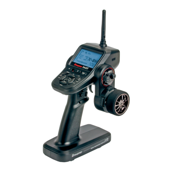
- Page 1 Manual X-8N 4 channel HoTT radio control Order no.: S1018 GRAUPNER/SJ GmbH. Henriettenstr.96, KG D-73230 KIRCHHEIM/TECK GERMANY...
- Page 2 E.P.A menu ................. 22 for mistakes, incomplete information and printing errors. Graupner/SJ reserves the right to alter the DR/EXPO menu ..............22 characteristics and features of the software and TRIM menu .................
-
Page 3: Foreword
Notice: A general survey of the rechargeable batteries, chargers and measuring devices for checking the power sources can be found in the GRAUPNER main catalogue FS or on the Internet at www.graupner.de. Technical data Transmitter X-8N:... -
Page 4: Delivered Items
You must therefore only ever use compatible original connectors of the same type. You must also only use original charging cables with a sufficient wire cross-section. The set includes: • X-8N HoTT transmitter • GR-8 receiver • NiMh battery 2000 mAh/4 cells •... -
Page 5: Key To The Symbols
INNOVATION & TECHNOLOGY Key to the Symbols Attention! This symbol alerts you to the following notes which the user must observe. Neglecting this information may have an adverse effect on the system’s proper function and the safety of the operator. Warning! This symbol alerts you to prohibited actions which the user must always observe. -
Page 6: Safety Notes
Safety notes Attention! These safety instructions are intended not only to protect the product, but also for your own and other people’s safety. There- fore please read this section very carefully before using the product! Do not carelessly leave the packaging material lying around, since it might become a dangerous toy for children. ... -
Page 7: Information On Handling Batteries
INNOVATION & TECHNOLOGY Information on handling batteries Attention! Protect all equipment from dust, dirt, moisture. Only use in dry locations. Do not use any damaged battery. Risk of injury! Any alterations to the battery can cause serious injury. Risk of fire! ... -
Page 8: General Operating Instructions
Information on handling the transmitter Attention! Also while programming the transmitter, make sure that a connected motor cannot accidentally start. Disconnect the fuel supply or drive battery beforehand. Risk of fire! Avoid every kind of short-circuit in all sockets of the transmitter! Use only the suitable connectors. In no case ... - Page 9 INNOVATION & TECHNOLOGY Routing the receiver’s antenna The receiver and the antennas must be positioned as far away as possible from any drive components. If the model’s hull is made of carbon fiber material, the ends of the antennas should always extend outside of the hull.
- Page 10 Follow the specific recommendations included in the motor’s operating and installation instructions. For further details about interference filters, refer to the Graupner RC main catalog or on the web at www.graupner.de. Servo interference filters for extension cables Order No. 1040 The servo interference filter is necessary when an extended-length servo cable is used.
- Page 11 Components and accessories As manufacturer of this equipment, Graupner/SJ GmbH recommends only components and accessories which have been tested and approved by Graupner for suitability, functioning and safety. Where this recommendation is followed, Graupner/SJ retains responsibility for the product. Graupner/SJ cannot accept any liability for non-approved parts or accessories supplied by other manufacturers and cannot assess every individual third party product as to suitability of use without safety risk.
-
Page 12: Manufacturer's Declaration On Behalf Of Graupner/Sj Gmbh
If material defects or manufacturing faults should arise in a product distributed by us in the Federal Republic of Germany and purchased by a consumer (§ 13 BGB), we, Graupner/SJ GmbH D-73230 Kirchheim/Teck, Germany, acknowledge the obligation to correct those defects within the limitations described below. -
Page 13: Operating Elements
The battery and the transmitter can be damaged. Risk of fire! The charge socket is protected from reverse polarity by a protection switch. Original Graupner chargers detect the charge state of the battery. The al- lowed charge current should not be higher than 1A, otherwise the switch and other components can be damaged. -
Page 14: Adjusting The Neutralization Springs
Adjusting the neutralization springs The adjusting screw for adjusting the neutralization spring for the steering wheel is located in the housing below the wheel. By turning the screw left or right, the reset force is increased or decreased. The adjusting screw for adjusting the neutralization spring for the throttle lever is located in the housing at the throttle lever. -
Page 15: Binding And Range Test
Binding and range test Binding: In order to be able to establish a connection to the transmitter, the Graupner-HoTT receiver has first to be "bound" to "its own" Graupner-HoTT transmitter. This procedure is called "binding". You can also select before BINDING, in the line TELEMETRY, whether the telemetry data should be displayed or not (see "RF SET menu") However, "binding"... -
Page 16: Start Display
Range test: Perform a range test of the Graupner HoTT 2.4 system, by observing the following instructions. If necessary, look for an assistant when performing the range test. Install the receiver, which preferably has already been bound to the transmitter, in the model. -
Page 17: Layout Of Switches And Buttons
INNOVATION & TECHNOLOGY Layout of switches and buttons TR4/TR5/PS2 Throttle lever PS1/Dial TR1/TR2/TR3 TR4/TR5/PS2 Steering wheel... -
Page 18: Button Functions
Button functions FUNC = Main menu, go to main menu Button combinations for menu quick access ESC = go to previous menu FUNC+ESC = Display servo bar ENT = Select INC+DEC = Resets changes in the settings INC, DEC, DOWN, UP = go to various menus UP+DOWN = Hidden mode INC+DEC+ENTER = Activates or deactivates or change values... -
Page 19: Mod. Sel Menu
INNOVATION & TECHNOLOGY Display 1/4 Display 2/4 MOD. SEL: Select model memory TRIM: TRIM, Sub-Trim MOD Name: Change model name B.R.A: Brake setting (ATL) MOD COPY: Copy model memory TH RESP: Throttle response speed MOD RES: Delete model memory / reset TIMER: Lap timer, stopwatch, lap time list RF-SET: HF / Binding / Range test S / SPEED: Steering/throttle servo speed... -
Page 20: Mod Name Menu
MOD NAME menu In this menu, you can enter model and user names. The keypad appears as shown in the figure below if "MODEL NAME" or USER NAME" are selected. You can enter 10 characters for the model name and 15 characters for the user name. - Page 21 (Observe the information from the servo manufacturer) Attention: The setting SUMD-V2 can only be used for Graupner servos, sensors and controllers supporting this function! Attention: Follow the instructions on the screen, in order...
-
Page 22: Reverse Menu
REVERSE menu In this menu, the direction of the servo rotation for the respective channel is set. Select the channel on the left side, by pressing the UP and DOWN buttons. With the ENTER button, you toggle between NOR (Normal) and REV (Reverse) and thus change the direction of the servo's rotation. - Page 23 INNOVATION & TECHNOLOGY Throttle channel settings: In this menu, a throttle curve with 4 points can be established. Curve: ON - OFF activates or deactivates the throttle curve 0% -> 0% : display of the current position of the throttle lever in percent POINT : N - H = Neutral - Full throttle...
-
Page 24: Trim Menu
If you have highlighted the field 0% in the POINT line and then 3x press the INC button, Trim offset appears in the 2nd line. Using the UP/DOWN buttons you can move the entire curve up or down. TRIM menu In this menu, the trimming for each channel can be performed. -
Page 25: Th Resp Menu
INNOVATION & TECHNOLOGY TH RESP menu In this menu, one point each can be set in the throttle travel and in the brake travel, from which the control starts. When operating the throttle lever in the direction of throttle or brake, the servo immediately jumps to this point, from where the control starts. - Page 26 The timer function is started or stopped by assigning switches in the SW FUN menu. The function is executed as follows: • Menu: LAP TIMER, FINISH is shown inversed • By pressing INC/DEC simultaneously, the timer is set in standby, the FINISH display changes to READY, the timer is started by accelerating •...
-
Page 27: S/Speed Menu
INNOVATION & TECHNOLOGY S/SPEED menu In this menu, the servo speed for the steering and throttle servo can be set. For the steering servo, you can set the speed for left and right and for forward and return travel separately. For the throttle servo, a point can be set at which the speed is set in two steps. -
Page 28: A.b.s. Menu
A.B.S. menu In this menu, the A.B.S. function can be set. A.B.S. enables a better braking response, since the brake is actuated in pulses. ACT: INH = function OFF, ACT= function ON SW: Display of switches which can be assigned to this function in the "SW FUN"... -
Page 29: Pumping Menu
INNOVATION & TECHNOLOGY PUMPING menu In this menu, the "PUMPING" function can be set. PUMPING enables automatic throttle activations, e.g. dur- ing refuelling, so the motor does not overgrease or go out when in idle. You can set the strength of the throt- tle activation in the POS line. -
Page 30: P/Mix Menu
P/MIX menu In this menu, the 5 free mixers can be set. When selecting a mixer from the list, the following display appears, in which you can make the settings. To the right of the mixer, there is the status display, whether the mixer is switched On of Off. - Page 31 INNOVATION & TECHNOLOGY SW FUN menu In this menu, you can assign a function to trim buttons, switches and rotary controls. By default, some buttons and switches have already been assigned functions, which can be assigned again as all the others, as follows: After selecting a switch with the UP/DOWN buttons, press Enter, and the menu with the possible functions for this switch appears.
- Page 32 SPD ST RR Speed steering servo right return path (S/SPEED menu) SPD ST LR Speed steering servo left return path (S/SPEED menu) SPD TH HG Speed throttle servo range High (S/SPEED menu) SPD TH NT Speed throttle servo range Neutral (S/SPEED menu) ABS TRG ABS activation point (ABS menu) ABS MOVE...
-
Page 33: S/Mode Menu
INNOVATION & TECHNOLOGY Meaning of the functions for PS1~ PS2,TR1A~TR5B, TH, ST Switch LAP TIMER Activate stopwatch for lap time (TIMER menu) LAP STOP Stopping the split time (TIMER menu) UP TIMER Stopwatch (counting up) (TIMER menu) DN TIMER Stopwatch (counting down) (TIMER menu) START MOD Activate start mode (START menu) CL ST... - Page 34 If only DUAL ESC is activated, line SPD RATE appears additionally, in which the speed for the connected speed controllers can be defined. SPD RATE: 0 - 100% ST MODE (steering) ESC MODE (2 drives) TANK SET (track vehicles) ST MODE: TYPE 1 = rotation only possible when standing, TYPE 2 = rotation only possible when driving SPD RATE: Setting the maximum speed of the drive, 0 - 100%...
-
Page 35: Servo Menu
INNOVATION & TECHNOLOGY BOAT SET (boat) These mixers can actuate e.g. a second drive (ESC) ST -> 3CH: mixer from steering to channel 3, mixing rate from -100 to +100% adjustable 3CH -> ST: mixer from channel 3 to steering, mixing rate from -100 to +100% adjustable SERVO menu Servo monitor (only display) -
Page 36: Telemetry Menu
TELEMETRY MENU Telemetry menu display with bound HoTT receiver (Gr-12/16/24/32) In this menu, you can make the telemetry settings, monitor the connection between transmitter and receiver, set the voice output and recognize which sensors are connected. SETTING & DATA VIEW: Here, you enter the telemetry menu and you can make settings. - Page 37 INNOVATION & TECHNOLOGY Voice play list Out of the listed devices in the SUMD-V2 system (transmitter, receiver, servo, etc.), you can combine individual voice announcements in a play list. Select the desired announcement in the menu of the device and press ENTER. The voice output is then called from this play list. (switch assignment in the SW FUN menu, function FIX.VOICE) DEVICE MANAGEMENT Menu for the administration of the devices connected to the receiver, if SUMD-V2 is set for the...
-
Page 38: Telemetry Display
Telemetry display In order to display the telemetry data, press the INC or DEC button from the main screen. Then, all available telemetry screens are displayed (only with bound receiver), depending on the connected sensors or devices. The selection of the device or sensor is then set by pressing the INC or DEC buttons. -
Page 39: Firmware Update Transmitter
INNOVATION & TECHNOLOGY INTERFACE In this menu item it is defined, via which port of the transmitter the telemetry data will be transmitted to the outside. DATA PORT: If you select this setting, the telemetry data will be output via the DATA socket on the rear side of the transmitter. -
Page 40: Operating Receiver Gr-8
Operating receiver GR-8 Receiver terminal assignment Meaning LED display red LED green LED not bound flashes bound error flashes binding flashes flashes Function Alternative CH 1 Channel 1 signal output SUMD-V2 BUS system Battery connection CH 2 Channel 2 signal output SUMD-V2 BUS system Battery connection CH 3... - Page 41 INNOVATION & TECHNOLOGY GR-8 receiver menu in the telemetry Display screen (only display) S-QUA: transmission quality S-STR: transmission power S-dBm: transmission power in dBm RX-TEMP: receiver temperature LOSS PACK: Lost data packets in milliseconds BATT VOLT: receiver voltage LOW VOLT: warning threshold for min. receiver voltage Setting screen for warning thresholds and telemetry language AL RX-V: warning threshold for receiver voltage...
-
Page 42: Connection Example For Engine-Powered And Electric-Powered Models
Connection example for engine-powered and electric-powered models Voltage sensor cable (red) Connect with Battery + Pol Speed controller Battery connection Motor connection On-Off switch Temp./Volt. Temperature sensor Sensor Channel 3+4 Steering servo Channel 2 Channel 1 Connection example for electric-powered model Temperature sensor fasten to the cylinder head Receiver... -
Page 43: Firmware Update Receiver
USB interface, order no. 7168.6, and adapter lead, order no. 7168.6A or 7168.S, which are available separately. The programs and files required can be found in the Download area for the corresponding products at www.graupner.de. Connect the adapter lead 7168.S to the USB interface order no. 7168.6. The connectors are reverse polarity protected: note the small chamfers on the sides. -
Page 44: Notes
Notes... -
Page 45: Notes
INNOVATION & TECHNOLOGY Notes... -
Page 46: Notes
Notes Recommended accessories • 97171 Brushless GM-GENIUS PRO 90R +T >=5.5T • 97170 Brushless GM-GENIUS PRO 120R +T >=3.5T • 33000.6 Transmitter bag • S8351 HoTT Bluetooth ext. module • S8362 Temperature and voltage sensor • 33000.11 Neutralisation spring hard 0.50 (4 pieces) •... -
Page 47: Declaration Of Conformity
ä ü f Ausstellungsdatum / Date of issue 15.12.2014 Graupner X-8N Transmitter - S1018 : Graupner X-8N Transmitter KCC Certification Number: MSIP-CRM-sjr-16006200 FCC ID : SNL-16006200 Graupner GR-8 Receiver - 33504: GR-8 Receiver FCC ID: SNL-16005700... -
Page 48: Warranty
Pour adresses des points de service situés en dehors de sories is not covered by the guaratee. The user´s legal rights l‘Allemagne s‘il vous plaît se référer à www.graupner.de/fr/. and claims under garantee are not affected by this guarantee. Please check the product carefully for defects before you are make a claim or send the item to us, since we are obliged to make a charge for our cost if the product is found to be free of faults.
Need help?
Do you have a question about the X-8N and is the answer not in the manual?
Questions and answers