Table of Contents
Advertisement
Quick Links
TRP1000-OD
Troposcatter C-Band Outdoor Amplifier
Installation and Operation Manual
Part Number MN-TRP1000-OD
Revision 0
IMPORTANT NOTE: The information contained in this document supersedes all previously published
information regarding this product. Product specifications are subject to change without prior notice.
Advertisement
Table of Contents

Subscribe to Our Youtube Channel
Related Manuals for Comtech EF Data TRP1000-OD


Summary of Contents for Comtech EF Data TRP1000-OD
-
Page 1: Installation And Operation Manual
TRP1000-OD Troposcatter C-Band Outdoor Amplifier Installation and Operation Manual Part Number MN-TRP1000-OD Revision 0 IMPORTANT NOTE: The information contained in this document supersedes all previously published information regarding this product. Product specifications are subject to change without prior notice. -
Page 2: Revision History
TRP1000-4450 Troposcatter C-Band Outdoor Amplifier Revision 0 Copyright © 2017 Comtech EF Data. All rights reserved. Printed in the USA. Comtech EF Data, 2114 West 7th Street, Tempe, Arizona 85281 USA, 480.333.2200, FAX: 480.333.2161 Revision History Date Description 6-2017 Initial Release. - Page 3 3 B 3 B E lectrical Safety Notice ......................viii Getting Help ..........................ix Contacting Comtech EF Data ....................... ix Returning a Product for Upgrade or Repair .................. x 4 B 4 B I nstallation Guidelines Regarding Power Line Quality ............. xi 5 B 5 B W arranty Policy ........................xi...
- Page 4 Perform the FTP Upload Procedures ................3–8 3.4.1 Perform the Automated Serial-Based FTP Upload Procedure (CReflash) ....3–8 3.4.2 Perform the Ethernet-based FTP Upload Procedure ........... 3–9 CHAPTER 4. ETHERNET-BASED REMOTE PRODUCT MANAGEMENT ..... 4–1 Overview ........................4–1 Table of Contents MN-TRP1000-OD...
- Page 5 4.5.4.4.5 Status | Statistics ..................4–22 4.5.4.4.6 Status | MOP ....................4–23 CHAPTER 5. SERIAL-BASED REMOTE PRODUCT MANAGEMENT ....5–1 Overview ........................5–1 Key Operational Parameters ..................5–1 5.2.1 Faults ..........................5–2 5.2.2 Some Common Commands ..................5–2 Table of Contents MN-TRP1000-OD...
- Page 6 LIST OF TABLES Table 1-1. RF Specifications ......................1–8 Table 1-2. Prime Power Requirements ..................1–9 Table 2-1. Connector ‘J3 | AC IN’ Pin Assignments ..............2–3 Table 2-2. Connector ‘J6 | COMM 1’ Pin Assignments ............... 2–5 Table of Contents MN-TRP1000-OD...
- Page 7 Figure 4-9. Status | Status Page ....................4–19 Figure 4-10. Status | FETs Page ....................4–20 Figure 4-11. Status | Events Page ..................... 4–21 Figure 4-12. Status | Statistics Page ..................4–22 Figure 4-13. Status | MOP Page ....................4–23 Table of Contents MN-TRP1000-OD...
- Page 8 Monitor & Control Processor Management Information Base MTBF Mean Time Between Failures Network Management System Object Identifiers Retrieve Alarm Status Retrieve Configuration Status Radio Frequency Retrieve Maintenance Status SSPA Solid State Power Amplifier VSWR Voltage Standing Wave Ratio Table of Contents MN-TRP1000-OD...
-
Page 9: Revision
Disclaimer Comtech EF Data has reviewed this manual thoroughly in order to provide an easy-to-use guide to this equipment. All statements, technical information, and recommendations in this manual and in any guides or related documents are believed reliable, but the accuracy and completeness thereof are not guaranteed or warranted, and they are not intended to be, nor should they be understood to be, representations or warranties concerning the products described. - Page 10 Metric conversion information is located on the inside back cover of this manual. Comtech EF Data furnishes this information to assist in the cross-referencing of non-Metric to Metric conversions. E lectrical Safety Notice 3 B 3 B Neutral Fusing – Double pole/neutral fusing is used on the prime power supply input. Preface viii MN-TRP1000-OD...
-
Page 11: Getting Help
Be prepared to provide the product model number and its serial number. Contact Comtech EF Data Customer & Technical Support during normal business hours (Monday through Friday, 8 A.M. to 5 P.M Mountain Standard Time (MST)): For:... - Page 12 Service hyperlink, and read the Return Material Authorization section in its entirety. Request a Return Material Authorization Number: On the Comtech EF Data Home page: From the SUPPORT column at the bottom of the • page, select the RMA Request hyperlink;...
- Page 13 Comtech EF Data is responsible for the freight charges only for return of the equipment from the factory to the owner. Comtech EF Data will return the equipment by the same method (i.e., Air, Express, Surface) as the equipment was sent to Comtech EF Data.
- Page 14 Comtech EF Data Corporation, would affect the reliability or detracts from the performance of any part of the product, or is damaged as the result of use in a way or with equipment that had not been previously approved by Comtech EF Data Corporation.
-
Page 15: Chapter 1. Introduction
Before operation, read Section 1.4.6 “Important Information on Temperature and RF Overdrive.” The compact, thermally efficient design and beneficial features of the Comtech EF Data TRP1000-4450-OD Troposcatter C-Band Outdoor Amplifier (Figure 1-1) – referred to throughout this manual as the TRP1000-4450, SSPA, TRP-1000-OD, or amplifier – are the result of Comtech EF Data’s extensive experience in the design of outdoor RF amplifiers and transceivers. -
Page 16: Functional Description
Revision 0 Functional Description Each TRP1000-4450 consists of a Comtech EF Data Solid-State Power Amplifier (SSPA) module, a Monitor/Control Processor (MCP), Forward, Reflected, and Input RF Power monitoring, a power supply, and thermal management system with heat sinks and cooling fans. The amplifier features a proprietary Comtech EF Data low-loss combining technique and MCP-based temperature-versus-gain compensation circuitry. -
Page 17: Complete Temperature Testing
The TRP1000-4450’s built-in data logging capability greatly enhances system maintainability. By recording critical operational parameters such as temperature, output power, mute status, etc. at time stamped intervals, the user can quickly gather intelligence about not only the unit itself, but also the unit’s operational environment. Introduction 1–3 MN-TRP1000-OD... -
Page 18: Theory Of Operation
Temp Sensor RF Fans Inp Pwr TX IN CA-0021324 TX OUT Fwd Pwr OUTPUT SAMPLE CA-0020988 CA-00231332 PS MODULE PL-0022293 Fans +24V COMM 1 Status Monitor & Control LEDs EMI Filter AC IN Figure 1-2. TRP1000-4450-OD Block Diagram Introduction 1–4 MN-TRP1000-OD... -
Page 19: Sspa Module
RF heat sink. The amplifier module temperature is monitored and, if for any reason the amplifier temperature exceeds a safe preset limit, the amplifier module supply is shut down to protect the unit from thermal failure. Introduction 1–5 MN-TRP1000-OD... -
Page 20: Important Information On Temperature And Rf Overdrive
≥66ºC), the unit will declare an Over Temperature Shutdown fault and will turn off the power supplies to the critical RF transistors for protection purposes. (The Amplifier/Outside Temperature Alarm has a hysteresis of 5ºC, while the Over Temperature Shutdown fault has a hysteresis of 10ºC). Introduction 1–6 MN-TRP1000-OD... -
Page 21: Over Drive (Excessive Rf Input Level)
Although the best protection against potentially degrading overdrive conditions is user attention and vigilance to the input and output levels as mentioned above, Comtech EF Data has implemented software updates that will help self-protect the unit and warn the user of gross overdrive conditions. -
Page 22: Summary Of Specifications
0.04 nanoseconds/MHz 1.5.1.18.2 Parabolic 0.005 nanoseconds/MHz 1.5.1.18.3 Ripple 1.0 nanoseconds peak to peak maximum 1.5.1.19 Residual AM (in dB below rated single carrier output as measured in a 4 kHz band) 1.5.1.19.1 to 4 kHz -35 dBc minimum Introduction 1–8 MN-TRP1000-OD... -
Page 23: Prime Power Requirements
4500 VA maximum @ 1.0 kW output 1.5.2.5 Inrush Current 144A peak 1.5.2.7 Ground Leakage Current 2 mA AC maximum 1.5.2.8 Power Interruption 20 msec min without performance degradation 1.5.2.9 EMC Conducted and Radiated EN55022-Level A FCC Part 15 Class A Introduction 1–9 MN-TRP1000-OD... -
Page 24: Dimensional Envelope
TRP1000-4450 Troposcatter C-Band Outdoor Amplifier Revision 0 Dimensional Envelope Note that all dimensions are in inches. Bracketed dimensions, where shown, are in metric units (mm). Figure 1-3. TRP1000-4450-OD Dimensional Envelope Introduction 1–10 MN-TRP1000-OD... -
Page 25: Chapter 2. System Connections, Installation And Startup
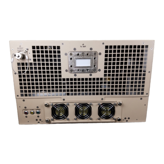
This chapter summarizes the connectors provided for all necessary external connections between the TRP1000-4450-OD Troposcatter C-Band Outdoor Amplifier and other equipment. Basic installation and operational startup information is provided in Sect.2.3 and Sect 2.4, respectively. Figure 2-1. TRP1000-4450-OD Interface Connectors - Front System Connections, Installation and Startup 2–1 MN-TRP1000-OD... -
Page 26: Interface Connectors
55dBm. In general, RF input levels above those which result in output saturation (>> Prated) should be avoided and, to prevent damge to the TRP1000-4450, should never exceed +30 dBm (refer to Section 1.4.6). System Connections, Installation and Startup 2–2 MN-TRP1000-OD... -
Page 27: Rf Output Connector 'J2 | Rf Out'
Specifications for the total power required from the prime power supply. Mating Connector: CEFD PN CN/MS-STPG03F07 (Glenair ITS3106F20- 19SF7). Table 2-1. Connector ‘J3 | AC IN’ Pin Assignments Pin # Description NEUTRAL (L2) LINE (L1) System Connections, Installation and Startup 2–3 MN-TRP1000-OD... -
Page 28: Remote Communications/Discrete Control Port Connector 'J6 | Comm 1'
The ‘J6 | COMM 1’ Remote Communications/Discrete Control connector is a 19-pin circular connector, type MS3112E14-19S. It is the primary input for remote M&C of the SSPA. Mating connector: ITT KPT06J14-19P or MS3116J14-19P. System Connections, Installation and Startup 2–4 MN-TRP1000-OD... -
Page 29: Output Sample Port Connector 'J9' (Type 'N' Female)
It is a Type ‘N’ female connector that provides a nominal -50 dB sample of the output signal. A calibration label, provided near the connector, shows the actual coupling values vs. frequency. System Connections, Installation and Startup 2–5 MN-TRP1000-OD... -
Page 30: Ground Connector
TRP1000-4450 Troposcatter C-Band Outdoor Amplifier Revision 0 2.2.6 Ground Connector A #10-32 stud is provided at the location shown in Figure 2-4 for connecting a common chassis ground among equipment. Figure 2-4. TRP1000-4450-OD Ground Connection System Connections, Installation and Startup 2–6 MN-TRP1000-OD... -
Page 31: Trp1000-4450-Od Installation
As shown in Figure 2-5, mounting holes are are provided for rack or panel installation of the TRP1000-4450. Several holes are available on the flat (bottom) surface of the TRP1000-4450 for mounting/installation purposes. Contact Comtech EF Data if factory furnished mounting kits are desired. -
Page 32: Power On The Unit
‘J3 | AC IN’ power connector to the appropriate prime power source. The Mute or Transmit status of the SSPA will automatically come up in the factory default state (factory default = transmit off, not muted). System Connections, Installation and Startup 2–8 MN-TRP1000-OD... -
Page 33: Chapter 3. Updating Firmware
By download from the Comtech EF Data Web site (www.comtechefdata.com) • From Comtech EF Data Customer Support during normal business hours, via e-mail or on CD by standard mail delivery (refer to Preface). The TRP1000-4450 Firmware Update process is as follows: •... -
Page 34: Getting Started: Prepare For The Firmware Download
‘FRW’ remote query to obtain, and make note of, the firmware information: Type (without the quotes) “<1/FRW?”<cr> at the command prompt to query the TRP1000-4450 for its Firmware Number. See Chapter 5. SERIAL-BASED REMOTE PRODUCT MANAGEMENT for information and instructions on using Remote Commands and Queries. Updating Firmware 3–2 MN-TRP1000-OD... -
Page 35: Figure 3-1. Temporary Folder Setup Using Windows Desktop
Select File > New > Folder to create the temporary folder. The new folder will be created in the active folder. • Right-click the ‘New Folder’ folder name, and then rename this folder to "temp" or some other convenient, unused name. Figure 3-2. Temporary Folder Setup using Windows Explorer Updating Firmware 3–3 MN-TRP1000-OD... -
Page 36: Figure 3-3. Temporary Folder Setup Using 'Run' And 'Browse'
For any Windows OS versions later than Windows 98 – Type “cmd” or “command”. Alternately, from [Start], select All Programs > Accessories > Command Prompt. Finally, from the Command-line ‘c:\>’ prompt, type “mkdir temp” or “md temp” (mkdir and md stand for make directory), and then click [OK]. Updating Firmware 3–4 MN-TRP1000-OD... -
Page 37: Figure 3-4. Temporary Folder Setup Using Windows Command Line
TRP1000-4450 Troposcatter C-Band Outdoor Amplifier Revision 0 Figure 3-4. Temporary Folder Setup using Windows Command Line There should now be a ‘temp’ folder created and available for placement of the firmware file download. Updating Firmware 3–5 MN-TRP1000-OD... -
Page 38: Download And Extract The Firmware Update
Revision 0 Download and Extract the Firmware Update 1. First, download the firmware update file from the Comtech EF Data Web site: a. Go online to www.comtechefdata.com. b. On the Main page – Under Support Information or the Support tab, select the Software Downloads hyperlink. -
Page 39: Figure 3-5. Download Firmware Archive File
Command-line. • Type “dir” to list the files extracted to the temporary directory from the downloaded archive file. The firmware files have been successfully downloaded and are now available for transfer to the TRP1000-4450-OD. Updating Firmware 3–7 MN-TRP1000-OD... -
Page 40: Perform The Ftp Upload Procedures
TRP1000-4450 serial or Telnet interface). • The latest firmware files have been downloaded or otherwise received from Comtech EF Data and are available on the user PC in an accessible temporary folder. 3.4.1 Perform the Automated Serial-Based FTP Upload Procedure (CReflash) 1. -
Page 41: Perform The Ethernet-Based Ftp Upload Procedure
The TRP1000-4450 returns the configured IP Address: >0001/IPA= xxx.xxx.xxx.xxx • Via the TRP1000-4450 Web Server Interface – View the IP Address/Range entry in the Network Maintenance section of the ‘Admin | Access’ page: Updating Firmware 3–9 MN-TRP1000-OD... - Page 42 The unit will return the Bulk, MnC, and FPGA firmware load information. • Via the TRP1000-4450 Web Server Interface – Open the ‘Config | Utility’ page and review the Firmware Information section to verify that the PC-to-Unit FTP file transfer was successful. Updating Firmware 3–10 MN-TRP1000-OD...
- Page 43 Re-energize the TRP1000-4450. The unit will reboot using the updated firmware image. 6. To update the other firmware image, repeat steps 1 through 5. The TRP1000-4450 is now operating with its latest firmware. The Ethernet- based firmware update process is now complete. Updating Firmware 3–11 MN-TRP1000-OD...
- Page 44 TRP1000-4450 Troposcatter C-Band Outdoor Amplifier Revision 0 BLANK PAGE Updating Firmware 3–12 MN-TRP1000-OD...
-
Page 45: Chapter 4. Ethernet-Based Remote Product Management
Overview This chapter describes the functionality of the TRP1000-4450 100BaseT/10BaseTx Ethernet Management Interface. This interface is generally modeled after interface of Comtech EF Data’s other Solid State Power Amplifier product lines. Refer to the Remote Commands Specifications tables found in Chapter 5. SERIAL-BASED REMOTE PRODUCT MANAGEMENT for detailed descriptions of the configuration parameters featured on the individual web pages depicted in this section. -
Page 46: Simple Network Management Protocol (Snmp) Interface
Monitoring System server. The following MIB files are associated with the TRP1000-4450: MIB File/Name Description (where ‘x’ is revision letter) ComtechEFData MIB file gives the root tree for ALL Comtech EF Data products and consists of only the following OID: Name: comtechEFData Type: MODULE-IDENTITY FW-0021006x.mib... -
Page 47: Snmp Community Strings
MIB2 SNMPv2 notifications: Authentication Failure 1.3.6.1.4.1.6247.95.1.3.1 The following Faults SNMPv1 traps and SNMPv2 notifications are supported by the TRP1000- 4450. Faults SNMPv1 traps: tropoSystemSummaryFaultEventV1 62479501 tropoSystemInputPowerEventV1 62479502 tropoSystemForwardPowerEventV1 62479503 tropoSystemReversePowerEventV1 62479504 tropoSystemRFOverdrivenEventV1 62479505 tropoSystemOperatingAirTemperatureEventV1 62479506 Ethernet-based Remote Product Management 4–3 MN-TRP1000-OD... - Page 48 62479520 tropoPSFan2EventV1 62479521 tropoPSFan3EventV1 62479522 tropoRFHeatSinkTemperatureEventV1 62479523 tropoRFExhaustTemperatureEventV1 62479524 tropoPS5V8EventV1 62479525 Faults SNMPv2 notifications: 1.3.6.1.4.1.6247.95.2.1.1 tropoSystemSummaryFaultEvent 1.3.6.1.4.1.6247.95.2.1.2 tropoSystemInputPowerEvent 1.3.6.1.4.1.6247.95.2.1.3 tropoSystemForwardPowerEvent 1.3.6.1.4.1.6247.50.2.1.4 tropoSystemReversePowerEvent 1.3.6.1.4.1.6247.95.2.1.5 tropoSystemRFOverdrivenEvent 1.3.6.1.4.1.6247.95.2.1.6 tropoSystemOperatingAirTemperatureEvent 1.3.6.1.4.1.6247.95.2.1.7 tropoSystemInternalTemperatureEvent 1.3.6.1.4.1.6247.95.2.1.8 tropoRFPowerSupply24VEvent 1.3.6.1.4.1.6247.95.2.1.9 tropoRFPowerSupply13V5Event 1.3.6.1.4.1.6247.95.2.1.10 tropoRFPowerSupply5V8Event Ethernet-based Remote Product Management 4–4 MN-TRP1000-OD...
- Page 49 TRP1000-4450 Troposcatter C-Band Outdoor Amplifier Revision 0 1.3.6.1.4.1.6247.95.2.1.11 tropoRFPowerSupplyNeg5V8Event 1.3.6.1.4.1.6247.95.2.1.12 tropoRFFan1Event 1.3.6.1.4.1.6247.95.2.1.13 tropoRFFan2Event 1.3.6.1.4.1.6247.95.2.1.14 tropoRFFan3Event 1.3.6.1.4.1.6247.95.2.1.15 tropoPS40VEvent 1.3.6.1.4.1.6247.95.2.1.16 tropoPS10VEvent tropoPS40VCurrentEvent 1.3.6.1.4.1.6247.95.2.1.17 tropoPS10VCurrentEvent 1.3.6.1.4.1.6247.95.2.1.18 tropoPS24VCurrentEvent 1.3.6.1.4.1.6247.95.2.1.19 tropoPSFan1Event 1.3.6.1.4.1.6247.95.2.1.20 tropoPSFan2Event 1.3.6.1.4.1.6247.95.2.1.21 tropoPSFan3Event 1.3.6.1.4.1.6247.95.2.1.22 tropoRFHeatSinkTemperatureEvent 1.3.6.1.4.1.6247.95.2.1.23 tropoRFExhaustTemperatureEvent 1.3.6.1.4.1.6247.95.2.1.24 tropoPS5V8Event 1.3.6.1.4.1.6247.95.2.1.25 Ethernet-based Remote Product Management 4–5 MN-TRP1000-OD...
-
Page 50: Telnet Interface
BASED REMOTE PRODUCT MANAGEMENT for detailed descriptions of the configuration parameters featured on the individual web pages shown in this chapter. 4.5.1 User Login From the PC, type http://192.168.1.4 (the default IP address for the TRP1000-4450) into the Address area of the browser: Ethernet-based Remote Product Management 4–6 MN-TRP1000-OD... - Page 51 Once the valid User Name and Password is accepted, the TRP1000-4450 Web Server Interface “splash” page displays, as per the example shown to the right (note that the Firmware Version listed here is subject to change): Ethernet-based Remote Product Management 4–7 MN-TRP1000-OD...
-
Page 52: Web Server Interface – Operational Features
If you edit a field, make sure to click the action button before you leave the page. If you go to another page without first clicking the action button, your changes are not saved. Ethernet-based Remote Product Management 4–8 MN-TRP1000-OD... -
Page 53: Drop-Down Lists
Summar Home Amplifier Access Contact SNMP Mask Status Utility FETs Events Statistics Beyond this top-level row of navigation tabs, the diagram illustrates the available primary (gray) page hyperlinks that afford you more specific functionality. Ethernet-based Remote Product Management 4–9 MN-TRP1000-OD... -
Page 54: Web Server Page Descriptions
From any location within the Web Server Interface, click the Home top navigation tab and/or the nested hyperlink to return to this top-level page. Use this page to identify the product and its current operating firmware version. Figure 4-1. Home | Home Page Ethernet-based Remote Product Management 4–10 MN-TRP1000-OD... -
Page 55: Home | Contact
TRP1000-4450 Troposcatter C-Band Outdoor Amplifier Revision 0 4.5.4.1.2 Home | Contact Use this page to reference basic contact information needed to reach Comtech EF Data Sales and Customer Support via phone, fax, or Web/e-mail hyperlinks. Figure 4-2. Home | Contact Page 4.5.4.2... -
Page 56: Figure 4-3. Admin | Access Page
These Password fields can be any alphanumeric combination with a maximum length of 10 characters. Make the desired configuration settings in this section, and then click [Change Access] to save these changes. Otherwise, click [Reset] to revert to the previously assigned System Account Access Information. Ethernet-based Remote Product Management 4–12 MN-TRP1000-OD... -
Page 57: Admin | Snmp
The Administrator can assign up to two SNMP Trap IP addresses and one SNMP Trap Community String. The SNMP Trap Community String field can be any combination of characters and a length of 0 - 20 characters: The factory default for the Trap Community String is comtech. Ethernet-based Remote Product Management 4–13 MN-TRP1000-OD... -
Page 58: Config (Trp1000-4450 Configuration) Pages
19200, or 38400 baud Data Bits - Parity - Stop Bits – Use the drop-down list to select the data bits, parity, andstop bits as 8-N-1, 7-E-2, or 7-O-2. Default is 8-N-1. Click [Save Changes] to save. Ethernet-based Remote Product Management 4–14 MN-TRP1000-OD... - Page 59 Alarm or Fault instead of the factory default of Mask, and the forward power drops below the specified value, the alarm/fault is indicated. Setting this parameter to the default value of 00.00 effectively disables the threshold. Click [Save Changes] to save. Ethernet-based Remote Product Management 4–15 MN-TRP1000-OD...
-
Page 60: Config | Mask
Low Forward Power Click [Change Alarm Mask] to save changes. Otherwise, click [Reset] to revert to the previously assigned Alarm Mask settings. Click [Refresh] to update the page with the current viewing and operating configuration. Ethernet-based Remote Product Management 4–16 MN-TRP1000-OD... -
Page 61: Config | Utility
Next Reboot Image Use the drop-down list to select Reboot Image 1 or 2. Press [Submit] when done. Perform Soft Reboot Click [Reboot Now] to reboot the TRP1000-4450 using the Current Active Firmware Image. Ethernet-based Remote Product Management 4–17 MN-TRP1000-OD... -
Page 62: Status Pages
‘Status | Summary’ page updates automatically once every 10 seconds. Even with this automatic refresh function, you may click [Refresh] to update the operational status parameters found on this page. Figure 4-8. Status | Summary Page Ethernet-based Remote Product Management 4–18 MN-TRP1000-OD... -
Page 63: Status | Status
‘Status | Status’ page updates automatically once every 10 seconds. Even with this automatic refresh function, you may click [Refresh] to update the operational status parameters found on this page. Figure 4-9. Status | Status Page Ethernet-based Remote Product Management 4–19 MN-TRP1000-OD... -
Page 64: Status | Fets
Use this page to review a read-only scrollable window that displays the operating currents of all FETs (Field Effect Transistors) installed in the RF amplifier. Figure 4-10. Status | FETs Page Click [Refresh] to update the page with the most recent RF Power FET Current Status parameters. Ethernet-based Remote Product Management 4–20 MN-TRP1000-OD... -
Page 65: Status | Events
Initialize Events Pointer – Select to reset the internal pointer to allow queries to start at the beginning of the stored events log. Click [Submit] to execute the choice – the window will update according to the selection made. Ethernet-based Remote Product Management 4–21 MN-TRP1000-OD... -
Page 66: Status | Statistics
Click [Submit] to execute the choice – the window Statistics Averaging: indicates if averaging is used or not. Values range from Disable or Enable. Click [Submit] to execute the choice – the window Ethernet-based Remote Product Management 4–22 MN-TRP1000-OD... -
Page 67: Status | Mop
• OTEMP = Outside Temperature • ATEMP = Heat Sink Temperature • ETEMP = Exhaust Temperature • PS40I = 40V current (Amps) • PS10I = 10V current (Amps) • PS24I = 24V current (Amps) Ethernet-based Remote Product Management 4–23 MN-TRP1000-OD... - Page 68 TRP1000-4450 Troposcatter C-Band Outdoor Amplifier Revision 0 Notes: Ethernet-based Remote Product Management 4–24 MN-TRP1000-OD...
-
Page 69: Chapter 5. Serial-Based Remote Product Management
MANAGEMENT Overview Serial-based remote product management of Comtech EF Data’s TRP1000-4450 Troposcatter C-Band Outdoor Amplifier is available using the TRP1000-4450’s ‘J6 | COMM 1’ port. Some key parameters and procedures and their associated remote commands and queries are summarized, followed by detailed instructions for use of the serial remote control communication command and query interface. -
Page 70: Faults
Additionally, the TRP1000-4450 also supports the serial command protocol over a Telnet session through the use of a 10/100Base-T Ethernet connection with the TRP1000-4450. The Ethernet communications interface also supports SNMP protocol, and provides a graphical user interface (GUI) through web pages that can be accessed using a web browser. Serial-based Remote Product Management 5–2 MN-TRP1000-OD... -
Page 71: Eia-485
This is a much simpler configuration in which the Controller device is connected directly to the Target via a two-wire-plus-ground connection. Controller-to-Target data is carried, via EIA-232 electrical levels, on one conductor, and Target-to-Controller data is carried in the other direction on the other conductor. Serial-based Remote Product Management 5–3 MN-TRP1000-OD... -
Page 72: Basic Protocol
=or ? Carriage Return ASCII code 60 ASCII code 47 ASCII codes 61 or 63 ASCII code 13 (1 character) (4 characters) (1 character) (3 characters) (1 character) (n characters) (1 character) EXAMPLE: <0412/MUT=1{CR} Serial-based Remote Product Management 5–4 MN-TRP1000-OD... -
Page 73: Start Of Packet
The controller does not have its own address. 5.3.4.3 Address Delimiter This is the ‘forward slash’ character ' / ' (ASCII code 47). Serial-based Remote Product Management 5–5 MN-TRP1000-OD... -
Page 74: Instruction Code
The ‘?’ code is used as the Query Operator (QO) and is used to indicate that the Target should return the current value of the parameters defined by the preceding byte. (ASCII code 63) EXAMPLE: In a message from Controller-to-Target, MUT? denotes ‘return the current state of the mute function’. Serial-based Remote Product Management 5–6 MN-TRP1000-OD... -
Page 75: Optional Message Arguments
# is returned, then the command was not accepted and the operator must resend the command. 5.3.4.6 Optional Message Arguments Arguments are not required for all messages. Arguments are ASCII codes for any printable character. Serial-based Remote Product Management 5–7 MN-TRP1000-OD... -
Page 76: End Of Packet
End-of-Life (EOL). While these commands are fully supported in this product, it is highly recommended that the equivalent new commands be used for new implementations. The new commands will generally follow the outdated commands. Serial-based Remote Product Management 5–8 MN-TRP1000-OD... -
Page 77: Remote Commands And Queries
5–23 5–30 5–33 5–11 5–16 5–23 5–30 5–34 5–12 5–16 5–23 5–30 5–34 5–12 5–17 5–24 5–31 5–34 5–12 5–17 5–24 5–31 5–13 5–17 5–27 5–31 5–13 5–18 5–28 5–31 5–14 5–19 5–28 5–32 Serial-based Remote Product Management 5–9 MN-TRP1000-OD... -
Page 78: Customer Commands
APM* (Same format as 1 = Enabled. Amplifier is set to the last user configured state command at power-up (on or off depending on the AMP setting). arguments) Example: <1/APM=1’cr’ >0001/APM=’cr’’lf’ Default Value: 0 Serial-based Remote Product Management 5–10 MN-TRP1000-OD... - Page 79 Instructs the unit to clear all Stored Alarms. This command CAA* Alarms takes no arguments. Example: <1/CAA=’cr’ >0001/CAA=’cr’’lf’ Clear All CAE= None Command only. CAE= Stored Clear all Stored Events. This command takes no arguments. CAE* Events Example: <1/CAE=’cr’ >0001/CAE=’cr’’lf’ Serial-based Remote Product Management 5–11 MN-TRP1000-OD...
- Page 80 01 and 31, mm = month of the year, DAY* (Same between 01 and 12 and yy = year, between 00 and 99 (1K format as OD to 2099) command Example (date = April 24, 2003): arguments) <1/DAY=240403’cr’ >0001/DAY=’cr’’lf’ Serial-based Remote Product Management 5–12 MN-TRP1000-OD...
- Page 81 DD/MM/YY = Day/Month/Year firmware released for details of Example: arguments) <1/FRW?’cr’ >0001/FRW= Boot: FW-0000082 0.0.1a 04/09/08 Bulk1: FW-0000078 0.0.1a 04/09/08 FW-0000080 0.0.1a 04/09/08 FW-0000081 0.0.1a 04/09/08 Bulk2: FW-0000078 0.0.1a 04/09/08 FW-0000080 0.0.1a 04/09/08 FW-0000081 0.0.1a 04/09/08 Serial-based Remote Product Management 5–13 MN-TRP1000-OD...
- Page 82 = a real number between 48.00 and 64.00 dBm. Example: <1/HPT=63.00’cr’ >0001/HPT=’cr’’lf’ Initialize IEP= None Command only. IEP= Events Resets internal pointer to allow RNE? Queries to start at the IEP? Pointer beginning of the stored events log. IEP* Example: <1/IEP=’cr’ >0001/IEP=’cr’’lf’ Serial-based Remote Product Management 5–14 MN-TRP1000-OD...
- Page 83 Telnet session with the new IP address. The IP address typed into the Telnet client software does not include the range parameter, so it would be: 192.168.1.4. Default Value: 192.168.001.004.24 Serial-based Remote Product Management 5–15 MN-TRP1000-OD...
- Page 84 0 = Disable 1 = Enable (all front panel LEDs are lit) Example: <0001/LAM=1’cr’ >0001/LAM=1’cr’’lf’ Default Value: 0 Retrieve next See RNE 145 bytes Query only. LNA= LNA? 5 unread query See RNE query. Stored Alarms Serial-based Remote Product Management 5–16 MN-TRP1000-OD...
- Page 85 Ethernet remote control. Default Value: 3 (Serial+Ethernet) Unit MAC 17 bytes Query only. MAC= MAC? MAC=xx-xx- Address xx-xx-xx-xx MAC address of the unit, reported in hexadecimal. Example: (See <0001/MAC?’cr’ description >0001/MAC=00-06-B0-00-D2-A7’cr’’lf’ for details of arguments) Serial-based Remote Product Management 5–17 MN-TRP1000-OD...
- Page 86 05-15-17 14:46:25 MAX OTEMP=019.2 05-15-17 14:46:27 MIN OTEMP=019.2 05-15-17 14:46:25 MAX ATEMP=022.3 05-15-17 14:46:25 MIN ATEMP=022.3 05-15-17 14:46:25 MAX ETEMP=022.7 05-15-17 14:46:27 MIN ETEMP=022.7 05-15-17 14:46:25 MAX PS40I=000.0 05-15-17 14:46:25 MAX PS10I=000.0 05-15-17 14:46:25 MAX PS24I=007.2 Serial-based Remote Product Management 5–18 MN-TRP1000-OD...
- Page 87 = Sealed PS Fan2 Speed f = Sealed PS Fan3 Speed g = High Input Power h = High Reverse Power i = Low Forward Power j=High Forward Power Example: <0001/MSK=2222222222’cr’ >0001/MSK=’cr’’lf’ Default Value: 2222222222 Serial-based Remote Product Management 5–19 MN-TRP1000-OD...
- Page 88 <1/PNM? return >0001/PNM=TRP0.0000000200’cr’’lf’ string) Retrieve Variable # Query only. RAS= RAS? RAS=x….x Alarm Status bytes The unit returns the alarm state for the following sections:. (See description RAS? for details of arguments) Serial-based Remote Product Management 5–20 MN-TRP1000-OD...
- Page 89 PS1-PS40I = 40V PS Current PS1-PS24I = 24 Volt PS current PS1-PS10I = 10 Volt PS current PS1-P5V8T = +5.8 Volt Power Supply PS1-PFAN1 = Module Fan 1 Speed PS1-PFAN2 = Module Fan 2 Speed Serial-based Remote Product Management 5–21 MN-TRP1000-OD...
- Page 90 PS1-PFAN3 = Module Fan 3 Speed (Continued) Example: <1/RAS?’cr’ >1/RAS=cr’ SYS-INPWR=NA SYS-FWPWR=NA SYS-RVPWR=NA SYS-OTEMP=OK SYS-INTMP=OK SYS-RFOVR=OK RF1-PS24V=OK RF1-PS13V=OK RF1-P5V8T=OK RF1-N5V8T=OK RF1-ATEMP=OK RF1-ETEMP=OK RF1-RFAN1=OK RF1-RFAN2=OK RF1-RFAN3=OK PS1-PS40V=NA PS1-PS10V=NA PS1-PS40I=OK PS1-PS24I=OK PS1-PS10I=OK PS1-P5V8T=OK PS1-PFAN1=OK PS1-PFAN2=OK PS1-PFAN3=OK Serial-based Remote Product Management 5–22 MN-TRP1000-OD...
- Page 91 Equipment The unit returns a string indicating the Model Number and Type the version of the M&C firmware installed in the unit. (See Example: description for details of <1/RET?’cr’ arguments) >0001/RET= TRP1000-4450-C VER: 1.1.1’cr’’lf’ Serial-based Remote Product Management 5–23 MN-TRP1000-OD...
- Page 92 (See description Where: for details of X= ‘cr’, 1’cr’ arguments) ‘cr’ = Power Supply 1 = RF Module Retrieve (Continued) Maintenance Where: Status Power Supply: (Continued) PFAN1 = PS Fan #1 Speed in Percent Serial-based Remote Product Management 5–24 MN-TRP1000-OD...
- Page 93 RVPWR = System RF Reverse Power in dBm ATEMP = Module Heatsink Temperature in deg C OTEMP = Outdoor Temperature in deg C ETEMP = Exhaust Temperature in deg C Example: <1/RMS? >1/RMS= >1/RMS= PFAN1=094.0 PFAN2=095.0 PFAN3=096.0 PS40V=039.9 PS40I=067.0 PS24I=022.0 PS10V=010.1 Serial-based Remote Product Management 5–25 MN-TRP1000-OD...
- Page 94 48 and 57) Qualifier) Controller) Qualifier) Controller) to Query Retrieve (Continued) Maintenance PS10I=097.0 Status P5V8T=005.8 (Continued) <1/RMS?1 >1/RMS= PS24V=024.0 PS13V=013.5 RP5V8=005.8 RN5V8=-05.8 RFAN1=095.0 RFAN2=096.0 RFAN3=097.0 FWPWR=>6200.00 INPWR=+25.00 RVPWR=+30.00 ATEMP=030.0 OTEMP=020.0 ETEMP=035.0 Serial-based Remote Product Management 5–26 MN-TRP1000-OD...
- Page 95 CC is Fault or Alarm description: Example: <1/RNE? >1/RNE= 06-22-15 11:57:50 RF1 FLT +13.5V PS 06-22-15 11:57:50 RF1 ALM Heat Sink Temp 06-22-15 11:57:50 RF1 ALM Exhaust Temp 06-22-15 11:57:51 RF1 FLT +24V PS Serial-based Remote Product Management 5–27 MN-TRP1000-OD...
- Page 96 Power Sets the power threshold used to generate a reverse power Threshold threshold alarm or fault condition (depending on the MSK state) Format xx.xx, Where: xx.xx = the reverse power threshold level in dBm Serial-based Remote Product Management 5–28 MN-TRP1000-OD...
- Page 97 Examples: <0001/SBR=9600’cr’ >0001/SBR=’cr’’lf’ <0001/SBR?’cr’ >0001/SBR=09600’cr’’lf’ Note: When changing baud rates remotely the response to the command will be returned using the same baud rate as that used to send the command. Default Value: 09600 Serial-based Remote Product Management 5–29 MN-TRP1000-OD...
- Page 98 Used to Query the unit’s nine-digit serial number in the form of SNO=xxxxxxxxx, Where: (See description xxxxxxxxx is the unit’s nine-digit serial number. for details of Note: This command is functionally identical to RSN. arguments) Example: <1/SNO?’cr’ >0001/SNO=072282040’cr’’lf’ Serial-based Remote Product Management 5–30 MN-TRP1000-OD...
- Page 99 255 bytes, Command or Query. SSC = SSC? SSC =x [1..128] System characters SNMP System Contact string. SSC! Contact Example: (See <1/SSC=Joe Net Admin description If not configured, it returns empty string: <1/SSC= arguments) Serial-based Remote Product Management 5–31 MN-TRP1000-OD...
- Page 100 Used to set the IP address of the first SNMP Trap destination STA! IP Address 1 IP Address 1 Where traps will be sent in the form: (See description xxx.xxx.xxx.xxx is the IP addresss Example: arguments) <1/STA=010.006.030.001 When not configured, returns >0001/STA=0.0.0.0 Serial-based Remote Product Management 5–32 MN-TRP1000-OD...
- Page 101 TIM * (Same minutes, between 00 and 59, and ss = seconds, between 00 format as and 59 command Example (time = 23 hours, 12 minutes and 59 seconds since arguments) midnight): <1/TIM=231259’cr’ >0001/TIM=’cr’’lf’ Serial-based Remote Product Management 5–33 MN-TRP1000-OD...
- Page 102 >0001/TNA=14’cr’’lf’ Total Number 2 bytes Query only. TNE= TNE? TNE=xx of Events Returns the number of unread entries in the stored events log. (See Example: description for details of <1/TNE? ’cr’ arguments) >0001/TNE=14’cr’’lf’ Serial-based Remote Product Management 5–34 MN-TRP1000-OD...
- Page 104 2114 85281 WEST TH STREET TEMPE ARIZONA 480 • 333 • 2200 PHONE 480 • 333 • 2161...
Need help?
Do you have a question about the TRP1000-OD and is the answer not in the manual?
Questions and answers