Table of Contents
Advertisement
Quick Links
Download this manual
See also:
User Manual
Advertisement
Table of Contents

Related Manuals for 3D Systems ProX 500


Summary of Contents for 3D Systems ProX 500
- Page 1 ProX™ 500 3D Production Printer Facility Guide Original Instructions...
-
Page 2: Table Of Contents
Facility Requirements Checklist - ProX 500 SLS 3D Printer and Auxiliary Equipment . . . . . . . . . . . . . . - Page 3 ProX 500 SLS 3D PRINTER FACILITY REQUIREMENTS POSTER . . . . . . . . . . . . . . . . . . . . . . . . . . . . . . . . . . . . . . . . . . . . 33 3D Systems, Inc.
-
Page 4: How To Prepare For Installation
3D Systems’ service and support . At the back of this guide, you will find the ProX 500 Facility Posters which give you a layout view of the facility requirements for the ProX 500 SLS 3D Printer, ProX Material Quality Control System, and auxiliary equipment . -
Page 5: What Your System Includes
Items consumed during part printing (“consumables”) such as powder, nitrogen, and filters NOTE: The ProX 500 SLS 3D Printer prints many types of parts out of several types of SLS materials . Each application has some unique requirements . Your system will most likely not include every component and material listed in this section . -
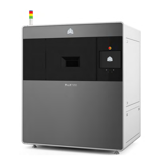
Page 6: Prox 500 Sls 3D Printer
The room must be air-conditioned, with no vents directly above the machine. Clearance around the process station is required so hinged access panels can be fully opened . See the ProX 500 SLS 3D Printer Facility Requirements Poster on page 33 for clearance requirements . -
Page 7: Prox Material Quality Control (Mqc) System
The ProX MQC System is an integral part of the ProX 500 3D Printer . It is responsible for properly regulating and controlling the SLS material used to print parts with the ProX 500, as well as breaking out parts from the print cake . Up to two printers can be used with a single MQC System . - Page 8 . The tag must be scanned to unlock the Fresh Material Input doors and add the material to the system . MQC System Operator Controls: User interface for operation of the MQC System . 3D Systems, Inc.
- Page 9 3D Systems Nitrogen Generator Connection: If the you have purchased a Nitrogen Generator from Dust Collector Port: Connection for the dust 3D Systems, it is connected here . collector . Oxygen Monitor Connection: If you have a room 2-Stage Hepa/Sock Filter: The material filter for the oxygen monitor, it is connected here .
-
Page 10: Part Transfer Cart
The print cake Extraction Cylinder, Part Transfer Tray and Part Transfer Cart, are used to remove the print cake from the ProX 500 print chamber and transport it to the MQC System . The system ships with the cylinder and tray . The transfer cart is optional . -
Page 11: Vacuum Cleaner
A customer-supplied step-up or step-down transformer is required if the facility does not have 208 VAC, 3-phase, 50/60 Hz, 10 kVA power . There are two U .S . models and one E .U . model available for purchase from 3D Systems: •... -
Page 12: Recommended Optional Equipment
Installed by: 3D Systems Source: 3D Systems For safety when working with nitrogen, 3D Systems recommends you install a room area oxygen monitor on the wall of your ProX 500 room . Refer to the safety guidelines included in the ProX 500 User Guide for information on safely working with nitrogen and oxygen . -
Page 13: Consumables
NOTE: Your site’s actual nitrogen consumption may vary from the nitrogen consumption estimate below . One ProX 500 SLS 3D Printer system will consume approximately 140 cubic meters (4944 cubic feet) of nitrogen gas per week . This estimate assumes seven days of continuous operation (24 hours/day) with seven purge cycles (one per day) . -
Page 14: Coolant
Coolant The 3D Systems-standard HRS024 SMC chiller has a fluid capacity of 5 liters (1.3 gallons). It requires a mixture of one pint of OptiShield to one gallon of distilled water . NOTE: Sufficient coolant must be available on site for 3D Systems to install your ProX 500 SLS System. To keep delays and costs to a minimum, verify that you have sufficient quantities of distilled water and OptiShield on hand before installation . -
Page 15: Facility Requirements Checklist
FACILITY REQUIREMENTS CHECKLIST In the sections that follow, you will find all the requirements your facility must meet before your ProX 500 SLS 3D Printing System can be installed . After your facility meets all these requirements, complete and sign the Facility Requirements Checklist on page 15 and submit it to 3D Systems Customer Support for review . -
Page 16: Facility Requirements Checklist - Prox 500 Sls 3D Printer And Auxiliary Equipment
FACILITY REQUIREMENTS CHECKLIST - ProX 500 SLS 3D PRINTER AND AUXILIARY EQUIPMENT IMPORTANT You must complete and sign this form before scheduling installation . The information on this form will be used to determine the necessary time that 3D Systems personnel will need to complete the installation . Contact name Phone... -
Page 17: Room Requirements
25 .4 mm (1 in) below the printer • The weight of the ProX 500 process station is 1361 kg (3000 lbs) . The weight of the station is distributed on four 68 mm (2 .7 in) diameter pads . -
Page 18: Atmosphere Requirements
ATMOSPHERE REQUIREMENTS The atmosphere in the ProX 500 SLS installation room must meet the following specifications: ATMOSPHERIC VARIABLES REQUIREMENTS Heating and air conditioning installed Room temperature controls A/C not blowing on top of process station Operating range: (16 to 27) °C; (60 to 80) °F Temperature Setpoint range: (18 to 24) °C;... -
Page 19: Electrical Requirements
. NOTE: The ProX 500 is designed to be connected to primary AC power directly from the facility’s power circuit to the machine’s input power line filter. This task must be performed by a qualified electrician. The facility’s power circuit must have a 50A branch protective circuit breaker or fused disconnect with lockout/tagout capabilities . -
Page 20: Grounding Requirements
All connections between powered equipment and the power panel must be grounded as shown in the diagram below . Main Power Power Panel Subpanels < 5 Ω < 5 Ω ProX 500 SLS System < 5 Ω < 5 Ω < 5 Ω < 5 Ω Non-Igniton... -
Page 21: Chiller Requirements
CHILLER REQUIREMENTS The ProX 500 SLS system incorporates a chiller to dissipate heat energy from the system . The model recommended by 3D Systems is the SMC HRS024, Thermo-chiller, Compact Type, Single Phase, 200 to 230VAC, 50-60hz . For complete information regarding your particular chiller model, refer to the OEM documentation which accompanied your unit . -
Page 22: Nitrogen And Compressed Air Requirements
• Nitrogen generator • Bulk nitrogen tank NOTE: Nitrogen supply systems are customer supplied and installed . 3D Systems does not service nitrogen supply equipment except for 3D Systems’ Nitrogen generator . Generator O Exhaust The nitrogen generator separates nitrogen from ambient air (CDA required), creating two air streams; N supply and O waste . -
Page 23: Receiving, Moving, And Storing The System
WHAT YOUR SHIPMENT INCLUDES All possible components of 3D Systems’ ProX 500 SLS 3D Printer system are listed below . They include a ProX 500 SLS 3D Printer for printing the parts, the system options for material handling, peripheral equipment for part finishing, and items consumed during part prints such as nitrogen, material, and filters. -
Page 24: Sls Materials And Filters
NOTE: For “bare” equipment weights and dimensions (without pallets and crates included), see System Component Weights and Dimensions on page 25 . ProX 500 SLS 3D PRINTER SYSTEM AND COMPONENTS SHIPPING WEIGHTS AND DIMENSIONS, DOMESTIC EXAMPLE Pallet or Crate Contents Weight... -
Page 25: Prox 500 Ship Kit
ProX 500 Ship Kit This accessories crate contains the following items: ProX 500 SLS PRINTER SYSTEM SHIP KIT CONTENTS (P/N 132599-00) Item No . Description 4100-01430 Dust Cloths (MCM 7124T12) 4100-01431 SWABS, Anti-static foam (tip .375" dia x .l81" L) length 6" - pack of 40... -
Page 26: System Component Weights And Dimensions
System Component Weights and Dimensions This table lists the “bare” (unpacked) dimensions and weights of all required and optional ProX 500 SLS Printer System and part finishing equipment. ProX 500 SLS PRINTER SYSTEM COMPONENT WEIGHTS AND DIMENSIONS Component Weight Width... -
Page 27: General Lifting And Moving Safety
Crating and uncrating the system is usually performed by 3D Systems service personnel . If it is necessary for the customer to perform these procedures, refer to the following steps . The procedure for uncrating both the ProX 500 SLS System and the MQC System are the same . -
Page 28: Moving Safety Guidelines
When moving uncrated equipment, insert forklift or pallet jack forks at lifting points labeled on the equipment frame . Only insert forks and lift equipment at labeled lifting points on equipment frame . Inserting forks and lifting at other locations can damage equipment and cause fatal injuries if the equipment tips or falls . 3D Systems, Inc. -
Page 29: Moving The Prox 500 Sls Printer Station And Mqc System
MOVING THE ProX 500 SLS PRINTER STATION AND MQC SYSTEM When moving the printer station observe the following: • Use a pallet jack or forklift with a load capacity of at least 2268 kg (5000 lb) . • Forks used to move the printer should be at least 48” (4ft / 1 .2m) long . -
Page 30: Prox 500 Printer And Mqc System Placement
INSTALLATION VERIFICATIONS (PERFORMED BY 3D SYSTEMS) Once all the ProX 500 3D SLS Printer System equipment is in place, your 3D Systems Field Service Representative will make the required nitrogen, power, and coolant hook-ups and connections . The representative will also level the process station, then perform the following verification procedures: •... -
Page 31: Network Requirements
The SLS equipment uses ethernet ports on the ProX 500 Printer and MQC System to send and receive powder transfer and system status messages . There is one ethernet connector on the ProX 500 system that is connected to the MQC and another that is connected to the facility’s LAN . -
Page 32: Contact Information
803 .326 .3900 Europe (+49) 6151 357-0 Germany: (+49) 6151 357-0 email: moreinfo@3dsystems .com Hong Kong: (+852) 29 23 50 77 www .3dsystems .com Switzerland: (+41) 26 439 95 90 NYSE: DDD UK: (+44) 1442 282 600 3D Systems, Inc. -
Page 33: Prox Mqc (Material Quality Control) System Facility Poster
ProX MQC (MATERIAL QUALITY CONTROL) SYSTEM FACILITY POSTER Rear Access Panels CEILING FRONT 3D Systems, Inc. -
Page 34: Prox 500 Sls 3D Printer Facility Requirements Poster
ProX 500 SLS 3D PRINTER FACILITY REQUIREMENTS POSTER Pneumatics Panel Transformer (step-up or step-down) Pressure • customer supplied and installed • required if facility does not have: Chiller power panel 208 VAC, 3-phase 50/60 Hz CHILLER • single phase 10 kVA power •... - Page 35 3D Systems, Inc . 333 Three D Systems Circle | Rock Hill, SC | 29730 www .3dsystems .com ©2015 3D Systems, Inc . All rights reserved . pn 134011-00 Rev . C...
Need help?
Do you have a question about the ProX 500 and is the answer not in the manual?
Questions and answers