Table of Contents
Advertisement
E
n
v
i
r
o
n
m
e
n
t
a
l
M
o
E
n
v
i
r
o
n
m
e
n
t
a
l
M
o
n
i
t
o
r
i
n
g
S
y
s
t
e
m
f
o
n
i
t
o
r
i
n
g
S
y
s
t
e
m
f
o
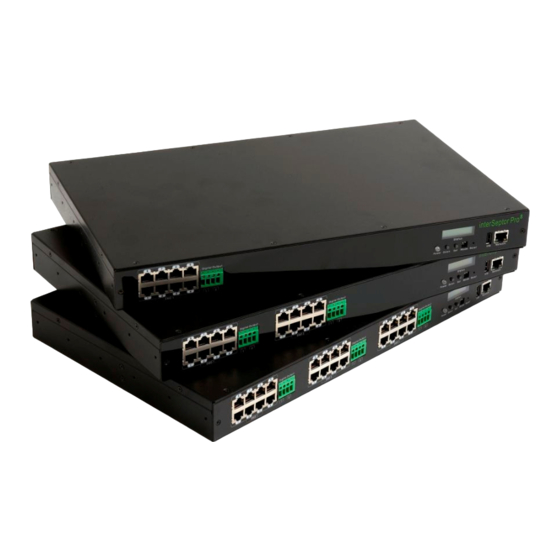
8-Port, 16-Port, 24-Port Versions
User Manual
T. +44 (0) 1672 511125
Email:
support@jacarta.co.uk
w
w
w
.
j
a
c
a
w
w
w
.
j
a
c
a
r
D
a
t
a
C
e
n
t
e
r
s
,
S
e
r
D
a
t
a
C
e
n
t
e
r
s
,
S
e
V1.1
r
t
a
.
c
o
.
u
k
r
t
a
.
c
o
.
u
k
r
v
e
r
R
o
o
m
s
,
R
a
c
k
s
r
v
e
r
R
o
o
m
s
,
R
a
c
k
s
Advertisement
Table of Contents

Subscribe to Our Youtube Channel
Related Manuals for jacarta interSeptor Pro


Summary of Contents for jacarta interSeptor Pro
- Page 1 8-Port, 16-Port, 24-Port Versions User Manual V1.1 T. +44 (0) 1672 511125 Email: support@jacarta.co.uk...
-
Page 2: Electronic Emission Notice
This device is RoHS compliant. WEEE In accordance with the European Directive 2002/96/EC on Waste Electrical and Electronic Equipment (WEEE) Jacarta will arrange for the appropriate disposal of the product (at the end of its serviceable life). Safety Information To reduce the risk of fire or electric shock, install the unit in a temperature-controlled indoor area •... -
Page 3: Table Of Contents
Features ..............6 Package Contents............7 Front View ..............8 Rear View..............8 Installation............... 9 Installing the interSeptor Pro via LAN ......9 LED Overview ............9 LCD Screen Overview..........10 2.3.1 LCD Screen in Idle Mode ........ 10 2.3.2 LCD Screen in Operation Mode ...... - Page 4 6.2.12 Trap Receiver Configuration ......40 6.2.13 Back to Main Menu.......... 40 6.2.14 End of interSeptor Pro Configuration ....40 Appendix A. Technical Information ........41 DIP Switch Definition..........41 EMD Cable Definition..........41 Appendix B. Firmware Upgrade........42 General Information ..........42 Updating interSeptor Pro firmware via Upgrade.exe 42...
- Page 5 Pro...
-
Page 6: Introduction
This is an integrated facility that requires an additional external GSM modem, by connecting the GSM modem the interSeptor Pro SMS Messages can be sent to up to 12 contacts. Please refer to “3.4.7 Sending SMS (Using GSM Modem)” for more detailed information. -
Page 7: Package Contents
Introduction Package Contents U-type handles (x 2) interSeptor Pro Temperature/Humidity Probe (EMD) (x 8, 16, 24 version dependent) 19″ Bracket (x 2) U-type handle screws (x 4) RJ45 to RJ45 male cable for EMD connection (x 1,2 ,3 version dependant) -
Page 8: Front View
Pro Introduction Front View Figure 1-1 interSeptor Pro front view Note: The USB 2.0 ports are standard interface connectors, designed primarily for use with an external keyboard or keypad. Rear View Figure 1-2 interSeptor Pro rear view... -
Page 9: Installation
1. Ensure your workstation has a web browser installed and is connected to your LAN via a hub/router/Switch. 2. Connect one end of a network cable to the LAN port on the front of the interSeptor Pro and the other end to your hub. -
Page 10: Lcd Screen Overview
You can view and configure the main system settings using the LCD screen and the Down and Set buttons on the front of the interSeptor Pro (see on page 8 for exact location of the switches). For additional security the LCD controls can be password protected with a default password of 0000. -
Page 11: Managing Interseptor Pro Via Web Browser
Figure 3-1 Use the Help and Back icons to navigate the pages 3.1 Initial Configuration The first time you access the interSeptor Pro via the web browser, please follow the steps below to configure the basic settings. 1. Click the Device Management menu. Click the Become Administrator button at the bottom of the page. -
Page 12: Device Monitoring
Pro. It also provides an overview of alarm status. This page is the default home page of the interSeptor. A summary of all the devices connected to the interSeptor Pro is presented. The parameters are updated automatically every 5 seconds. Figure 3-3 Comprehensive View... -
Page 13: Device Board Web
Monitoring interSeptor Pro The text color of each parameter indicates status: Text Color Status Green Normal Yellow Warning Critical Grey Unknown The text color of the alarm columns also indicates status: Text Color Status Alarm is active Green Alarm is inactive 3.2.2 Device Board Web Pages... -
Page 14: Identification Web
Pro 3.2.3 Identification Web Pages This page provides general interSeptor Pro identification information, including firmware version and the date and time. All the information in this page is read-only. Figure 3-5 Identification Web Page 3.2.4 Alarm Table Web Pages This page provides information on the number of currently active alarms, alarm ID, alarm time, and alarm description. -
Page 15: Device Management
3.3 Device Management The Device Management menu allows the configuration of EMD sensors, Dry contact sensors, and output controls connected to each of the device boards on the interSeptor Pro. There are six sub-menus in the Device Management menu: Device Board-1... - Page 16 For example, if a sensor reports 43% humidity in an environment where humidity is at 45%, you can set the humidity offset to 2% so the sensor can adjust its final reading. Alarm Type: If an alarm is connected to the interSeptor Pro, select from Normal Open, Normal Close or Disabled.
-
Page 17: Schedule Of Device Board Screens
Monitoring interSeptor Pro Configure the following settings: Device Name: Enter the device name. Normal Start-up: Select On(Close) or Off(Open) to configure the normal status of the device. Action: Select to Enable or Disable the digital output. Manual Control: Select Turn On to turn on a device manually or Turn Off to turn it off. -
Page 18: System Configuration
Delete button to delete the schedule. 3.4 System Configuration The System Configuration menu allows you to configure all system settings on the interSeptor Pro. Figure 3-10 System Configuration: Date & Time There are nine sub-menus in the System Configuration menu:... -
Page 19: Date And Time
Monitoring interSeptor Pro 3.4.1 Date and Time This page allows you (as administrator) to set the date and time of the interSeptor Pro manually or synchronize the settings with the computer time or an NTP (Network Time Protocol) server. Figure 3-11 Date and Time 3.4.2 System Configuration... -
Page 20: System Control
Pro, or assign a different port number for the communication protocol. You can also click the Reset to Default button to reset all default configurations for the interSeptor Pro, or the restart interSeptor Pro button to restart the interSeptor Pro. -
Page 21: Trap Receivers
Monitoring interSeptor Pro 3.4.5 Trap Receivers This page allows you (as administrator) to modify the settings for SNMP trap receivers (for SNMP Network Management). Figure 3-15 Trap receivers 3.4.6 Email Notification This page allows you (as administrator) to configure the mail server and mail receiver settings to send alert emails when an event occurs. -
Page 22: Sending Sms (Using Gsm Modem)
Follow the steps below to add/edit/delete a short message. 1. You have to connect the GSM modem to interSeptor Pro, as shown below: Figure 3-17 Connect GSM modem to interSeptor Pro 2. Set the GSM modem function to ENABLE. - Page 23 Monitoring interSeptor Pro 3. Add a new message for an SMS recipient. Figure 3-19 New SMS page Configure the following settings for a new message: Phone Number: Enter a phone number to send the SMS to. Duty From and Duty To: Enter a start and end time and only during this period of time the SMS recipient will be sent SMS messages, when events occur.
-
Page 24: External Links
Figure 3-22 the links appear on the left of the page 3.4.9 SSL Root CA Configuration You can download the Root CA certificate of the interSeptor Pro and the Root CA certificate of the interSeptor Pro for Java plug-in. The interSeptor Pro Root CA self-signed certificate contains the interSeptor Pro Root CA public key. -
Page 25: History Log
3.5 History Log The History Log menu displays detailed past activity for each connected EMD sensor and the interSeptor Pro system as a whole. Figure 3-24 History: History Log Index of Device-1 Page There are eleven sub-menus in the History Log menu:... -
Page 26: Extended Logs Of Devices
Pro Figure 3-26 History Log Data of Device-1 3.5.2 Extended Logs of Devices These pages give a consolidated view of the EMD parameters taken over a period on each of the three device boards. The minimum, maximum and the average values of temperature and humidity are shown. -
Page 27: Device Events
Figure 3-29 Device-2 Events Log Index page Figure 3-30 Events Log Data of Device-1 3.5.4 System Events This page lists all the system events. The administrator has the right to delete the entries. Figure 3-31 interSeptor Pro events page Figure 3-32 interSeptor Pro events log data... -
Page 28: Clear & Save
Pro 3.5.5 Clear & Save To save the interSeptor Pro log data to a file in Microsoft Excel format, click the links under the Save Log Data section. You can also clear the log data in this page. Figure 3-33 Clear and save log data page... -
Page 29: Monitoring Interseptor Pro Via Java Monitor
Alarm Window When changes are detected in the system configuration or in the status of the connected sensors, the interSeptor Pro displays a specific message in the Alarm Window. This type of status change message is an alarm. Figure 4-2 Alarm Window... -
Page 30: History Log Monitor
4.2 History Log Monitor Click the button in the top right-hand corner of the interSeptor Pro home page to display the EMD History Log Monitor. The EMD history log is presented in line graph. By default, all the EMD parameters will be shown on the same graph. You can select any combination of the parameters to be displayed by checking the check box next to each parameter on the monitor screen. -
Page 31: Extended History Log Monitor
4.3 Extended History Log Monitor Click the button in the top right-hand corner of the interSeptor Pro home page to display the EMD Extended History Log Monitor. This monitor shows the EMD extended history log in line graph. By default, all the EMD parameters will be shown on the same graph. You can select any combination of the parameters to be displayed on the graph by checking the check box next to each parameter on the monitor screen. -
Page 32: Managing The Interseptor Pro Via Snmp
5.3 Setting up SNMP Manager Software Follow the steps below to set up SNMP management software: 1. Add the MIB file in the interSeptor Pro CD-ROM to the MIB database of the SNMP manager. 2. Search for the interSeptor Pro in the network. -
Page 33: Configuration
1. Make sure you have a PC with the TCP/IP network installed. 2. Run command shell (i.e. Windows MS-DOS prompt). 3. By default DHCP is disabled, but if enabled the interSeptor Pro will try to acquire and IP address via DHCP on the network. -
Page 34: System Group Configuration
Pro 6.2.1 System Group Configuration From the configuration menu, press “1” to select this function and set the IP address, gateway address and other group parameters. The definitions of these parameters are listed below (see Figure 6-2). Figure 6-2: System Group Configuration Menu. -
Page 35: Telnet Control
Configuration No. Function Description Example/Remark HTTP Login Username HTTP access login string “iSPro” Login Password Administrator password for read and write access “admin” BOOTP/DHCP Control Enable/disable the BOOTP/DHCP Protocols Enabled TFTP Upgrade Control Enable/disable the TFTP protocol for firmware upgrades Enabled through the local network PING Echo Control... -
Page 36: Ssh Control
Pro 6.2.4 SSH Control From the control group menu, enter 7 to access the SSH configuration. Figure 6-5 SSH Configuration Menu Function Description Example SSH Control Enable/Disable the SSH Control Enabled SSH Port Configuration Port for SSH connections 6.2.5 HTTP Control... -
Page 37: Snmp Control
SNMP traps are not affected using this setting and always use UDP port 162. 6.2.7 Parameter Group Configuration From the configuration menu press “3” to modify the SNMP identification information and the speed of reading data from interSeptor Pro (see Figure 6-8) Figure 6-8 Parameter Configuration Menu No Function... -
Page 38: Emd Configuration
Pro 6.2.8 EMD Configuration Use the EMD Configuration and Monitoring option to configure sensor related information to the interSeptor Pro. Figure 6-9 EMD Configuration and Monitoring Menu No Function Description Example/Remark EMD status of Device Board-1 Access Device Board-1 monitoring menu EMD status of Device Board-2 Access Device Board-2 monitoring menu EMD status of Device Board-3. -
Page 39: Digital Output Control
If you wish to use a workstation with an SNMP manager installed, or if you wish to set more restrictive interSeptor Pro access, you can use the access table to add the IP addresses of the PC’s on which you wish to modify the access permissions (see Figure 6-12). -
Page 40: Trap Receiver Configuration
6.2.12 Trap Receiver Configuration If you want to send SNMP traps from the interSeptor Pro to an SNMP network management system, the IP address of the management station must be added to the interSeptor Pro list (see Figure 6- 13). -
Page 41: Appendix A. Technical Information
DIP Switch Definition Figure A-1 DIP switch Function Mode Manufacture Diagnostic Mode Reserved Reserved Operating Mode EMD Cable Definition The cable for EMD ports of the InterSeptor Pro (straight-through CAT5 network cable). RJ45 RJ45 Color White/ Orange Orange White/ Green Blue... -
Page 42: Appendix B. Firmware Upgrade
Pro. Updating interSeptor Pro firmware via Upgrade.exe 1. Open the upgrade.exe from the upgrade folder on the CD provided with the interSeptor Pro pack. 2. Click the Discover button to discover the interSeptor pro installed on the network. - Page 43 Appendix B Firmware Upgrade 4. Select the interSeptor Pro from the Device List and then click the modify button enter the User name and Password of the interSeptor Pro to be upgraded. Figure B-3 upgrade.exe modify page 5. Then click the upgrade button, click ok at the end of the upgrade process.
-
Page 44: Appendix C. Changing Baud Rate For Gsm Modem
Then reconnect HyperTerminal using the new baud rate. Now make the changes permanent with the following command. at&w (press enter) You should now be able to send SMS messages from your interSeptor Pro using your external GSM modem. If you require any assistance please contact support@jacarta.co.uk.
Need help?
Do you have a question about the interSeptor Pro and is the answer not in the manual?
Questions and answers