
Related Manuals for jacarta iMeter Master


Summary of Contents for jacarta iMeter Master
- Page 1 Master Ethernet Power & Environmental Monitoring System USER MANUAL v1.2 www.jacarta.com T. +44 (0) 1672 511125 Email: support@jacarta.com...
- Page 2 iMeter...
-
Page 3: Electronic Emission Notice
This device is RoHS compliant. WEEE In accordance with the European Directive 2002/96/EC on Waste Electrical and Electronic Equipment (WEEE) Jacarta will arrange for the appropriate disposal of the product (upon return of the product at the end of its serviceable life). Safety Information •... -
Page 4: Table Of Contents
iMeter Table of Contents Electronic Emission Notice Safety Information Table of Contents 1 - Presentation 1.1 Introduction 1.2 How to use this manual 1.3 Package contents 1.4 Front and rear panels 2 - Installation 2.1 Setting the IP address 2.2 Testing the IP address 2.3 Firmware upgrade 2.4 Setting up a sensor 2.5 Expansion ports... -
Page 5: Presentation
If you need any further information or help with using your unit then please contact us and one of our technical support staff will be only too pleased to help you with any information you require. 1.3 Package Contents The iMeter Master package contains the following items:- • 1x Product CD •... - Page 6 Operating System (OS) with a minimal set of drivers. If your device enters safe mode after rebooting then please contact us on support@jacarta.com • The unit may enter recovery mode if a firmware upgrade has been incomplete.
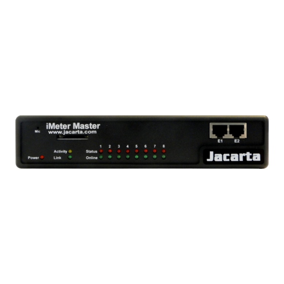
- Page 7 iMeter 4. USB port The unit is equipped with a single USB 1.1 port. This can be used, for example, to connect a USB GPRS/GSM compatible modem. 5. Mic Out This is used to connect an external microphone for voice modem applications. 6.
-
Page 8: Installation
iMeter 2. Installation 2.1 Setting up the IP address Every unit is shipped with the default IP address of 192.168.0.100. First we will go through the process of changing this IP address to fit another network configuration. Ensure the following items are available before starting:- •... - Page 9 iMeter d) You will now be presented with the following screen. e) Click on “Ethernet network” from the list on the left frame of the page. Don’t forget to set the subnet mask, default gateway and domain name server if DHCP is not used.
- Page 10 iMeter 2.2 Testing the new IP address with the “ping” command Once you have assigned the new IP address either connect the device to the local area network, or change the PC IP address so that it can route to the new IP address. Once this is done use the “ping”...
-
Page 11: Firmware Upgrade
2.3 Firmware upgrade If new firmware is required please contact us at support@jacarta.co.uk This tutorial provides you the information needed to upgrade the firmware. To get to the starting point of this tutorial: • Log in as administrator •... - Page 12 iMeter d) Click OK. The unit will then reboot in safe mode and be redirected to the safe mode web based interface. This can take some time, so please be patient. The page will display the following message while rebooting; e) Once the unit has rebooted the following page will be displayed.
-
Page 13: Setting Up A Sensor
In this section we will now go through the basic set up of a sensor. We will focus on the Jacarta temperature sensor; however this basic set up process is applicable to all of our sensors. If you require information on specific functions of a particular sensor then please contact us on support@jacarta.com. - Page 14 iMeter Note: another way of accessing this page is to click on the “sensors” tab indicated at the top of the page. d) Notification thresholds From this page various operations can be carried out as indicated above, also viewing of the current status (normal, low critical, high critical etc). In the screen shot above the sensor is indicating a temperature of 35 degrees C, and a status of High Warning.
- Page 15 iMeter Note: If this does not happen straight away press the browsers refresh button. If a sensor needs to be taken offline then click on the “sensor currently” button. This will offline the sensor without the need for it to be physically unplugged. Now the page will look something like below after taking the sensor offline.
- Page 16 iMeter e) Advanced sensor settings Near the bottom of the sensors page you will see the advanced mode button By clicking this you will get the following options :- Advanced mode functions Units: changes units from C to F or vice versa Rearm: The Rearm parameter is useful for sensors whose values can vary such as the temperature and humidity sensors.
- Page 17 iMeter Continuous Time to Report High Warning: As above but delays notification for “High Warning” Continuous Time to Report for Normal: As above but delays notification for return to “Normal” state Continuous Time to Report for Low Warning: As above, but delays notification for “Low Warning”...
-
Page 18: Expansion Ports
2.5 Expansion Ports The Jacarta iMeter Master is equipped with four expansion ports. This enables connection of up to four daisy chained expansion modules. The available expansion modules are; • The iMeter Slave, 8x RJ45 sensor ports • The iMeter DC16, 16x dry contact sensor ports. -
Page 19: Notifications
iMeter d) This will bring you to the following page, the extended port sensors page; e) Once the “Dual sensors” tab is clicked the browser will be directed to the familiar looking notification thresholds page (below). 3. Notifications Notifications define the action to take when the sensor gives a reading beyond the set thresholds. -
Page 20: Adding A Notification
iMeter 3.1 Adding a notification a) First click on the “notification wizard” b) The notification wizard page is displayed, as below; We will now go through setting up a few different ways of notification step by step. 3.2 SNMP Trap First we will set up a notification via SNMP trap, so that when the sensor reaches a certain threshold it will send a notification to an SNMP server. - Page 21 iMeter a) After selecting to add an SNMP fill in the following information; b) Once this information is correct you can press the “Add Trap Destination” button. After clicking this you have the option of inputting another trap, or clicking on “Next”.
- Page 22 iMeter On these screens the parameters for when to send the SNMP trap notification can be selected. In our example we have selected to bind the SNMP trap to the temperature sensor we have connected on port 1. The trap will be sent when the sensor reads a “High Critical”...
- Page 23 iMeter Now you will see the SNMP trap has been added to our notifications page:- Note: To remove this trap and make it inactive, highlight the notification and click remove. You can repeat this process to set up multiple SNMP traps for different sensors, or for multiple SNMP servers.
-
Page 24: Email
iMeter 3.3 E-mail This tutorial provides you the information needed to setup an E-Mail Notification. To get to the starting point of this tutorial: • Log in as administrator • Select the “Notifications” tab • Click “Notification Wizard” a) Select to set up an E-mail notification to show the following page; b) Clicking “Next”... - Page 25 iMeter c) Now input the SMTP server address and authentication details; Once the relevant information has been added click next. d) Now, as with the SNMP trap, the number of times to resend can be selected, and the time to elapse between each attempt. Click next when the parameters are filled in.
- Page 26 iMeter Click on “Finish” to be taken back to the main Notification tab. Click on create g) Create the notification link as before. Then click finish...
-
Page 27: Sms
iMeter h) Back at the main notification page there is the two notifications listed, the SNMP trap and the e-mail. As seen on this page, there is an SNMP trap set up to give notification of a “High Critical”, and an E-mail notification that will activate on a “High Warning”. 3.4 SMS Now, we will set up a notification so that an SMS message will be sent. - Page 28 iMeter b) Now either add multiple numbers, or click next. In our case we will click next. c) Now we will set up the message that will be sent to the phone on the following screen;...
- Page 29 iMeter Note: A macro is a script that returns specific data collected by the unit. In our example here the macro will tell the notification to contain the “description” (sensor name), the value (current sensor reading) and the status (high/low warning etc) these macros are common to all sensor notifications.
- Page 30 iMeter g) Again we now select the sensor to which to bind this notification too. As before, select the Temperature sensor on port 1. This time we will use this notification for a low warning. Then select the notification name we assigned, in this case we chose “SMS 1”.
- Page 31 iMeter Back at the main notification page, the page should display three types of notifications, the SNMP trap, E-mail and SMS.
-
Page 32: Mapping
However, with this information you should be able to follow the procedure for the other types of notifications easily, as they all follow a similar format. If you still encounter difficulties with this then please contact us on support@jacarta.com. 4. Mapping The mapping feature allows for an instant visual feedback as to a sensors position, and status. - Page 33 iMeter c) In this tutorial we are going to use a 3D map of a campus site. d) Choose to have the map as a top level map. e) There is now the option to finish or to continue adding sensors to the map. For this tutorial, click next.
- Page 34 iMeter g) After clicking next you will be directed to click the “Unlock” button. h) Sensor icons can now be dragged on to the map and positioned. After the sensors are in the correct position on the map click on “Lock” and then click on the “Finish”...
-
Page 35: Monitoring Via Map Interface
iMeter 4.2 Monitoring via the map interface Now we are going to look at how to monitor the sensor status and use the map interface. a) To see further information regarding a sensor you can click on its icon. First you must click on the “Lock Icons”... -
Page 36: Filters
iMeter 5. Filters 5.1 Sensor filters a) The iMeter comes equipped with the option to filter the sensor information which is displayed within the summary page. To enter the filter menu, select “Sensor Filters” from the dropdown tab on the left of the page:- b) Once you have clicked the tab you will be able to select the desired filter results by altering various fields of information contained within the sensor filter window;... -
Page 37: Syslog Filters
iMeter c) Altering the page reload interval can be achieved by using these options shown below; d) Once you have selected the desired filter options, the new settings will be displayed in the “Sensor Information” window found on the summary page. 5.2 Syslog filters a) Syslog filters enable customization of the syslog window. -
Page 38: Faq
iMeter c) Checking and un-checking various boxes within the Syslog filter window customizes the displayed information within the syslog. d) Altering the syslog reaload interval can be achieved by using the options shown below; e) Once you have selected the desired filter options, the new settings will be displayed in the “Sensor Information”... - Page 39 iMeter I have forgotten my units IP address I have forgotten the password for my unit How do I set up my routing table? How can I change my administrator password? What functions do different types of notifications provide? What is the heartbeat message? a) I can not see the temperature sensor displayed on summary page If after logging in for the first time with the temperature sensor connected, you may need to check your syslog filters for the temperature sensor.
- Page 40 iMeter LED patterns in Normal mode then LED patterns in Safe mode...
- Page 41 iMeter then ...
- Page 42 iMeter LED patterns in Recovery mode then LEDs run clockwise after the power is connected. From left to right each LED indicates 1st LED: U-Boot init 2nd LED: Kernel loaded with good CRC 3rd LED: Board init 4th LED: Serial port 5th LED: Ethernet 6th LED: NOR Flash...
- Page 43 iMeter e) I have forgotten the password for my unit. Hold down the reset button for 7 seconds. This will turn off the use password feature for the web based interface. This will remain turned off until you hold the button down for a further 7 seconds, or the unit announces “Now turning off password checking”.
- Page 44 iMeter Telephone call: Will call you and play a pre recorded message or a text to speech message. Siren and strobe: Will activate a siren and strobe light. Wake up / Shutdown: This will send a signal to wake or shut down a server. What is the Heartbeat message? This setting is to have the iMeter notify you it is still running.
Need help?
Do you have a question about the iMeter Master and is the answer not in the manual?
Questions and answers