
Subscribe to Our Youtube Channel
Related Manuals for Gossen MetraWatt ProFiTEST C-GB int.


Summary of Contents for Gossen MetraWatt ProFiTEST C-GB int.
- Page 1 Operating Instructions ® C-GB int. PROFiTEST 3-349-074-03 Test Instrument per DIN VDE 0100 17/12.14...
- Page 2 ® PROFiTEST C Measuring and Test Instrument Infrared Interface Interface Adapter black (for plug-on instructions see page 4) blue Control and Display Unit (PE) 3-Phase Measuring Adapter Test Plug Article No. Z521A Contact Surface Attention! Removing the Test Plug from the Measuring Adapter Disconnect L1, L2 and L3 from the mains before removing the test plug from the 3-phase measuring Replacement Fuses...
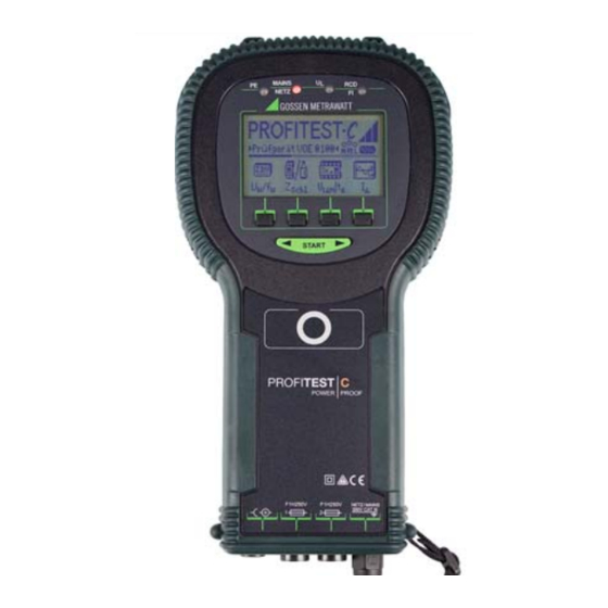
- Page 3 ® PROFiTEST C Control and Display Unit Netz Mains The scroll bar indicates which menu function Battery Level Display (continuous) is currently active. Key for the Selection of Basic Functions and Sub-Functions The desired menu (menu-driven operation) START functions can be displayed with the keys: Toggle Switch...
- Page 4 ® PC software WinProfi for communication with PRO TEST The free PC starter software WinProfi* is used for communication with ® your PROFiTEST C test instrument. WinProfi is available on our homepage with the following content and functions: • up-to-date test instrument software –...
-
Page 5: Table Of Contents
Contents Contents Page Page Applications ..................6 6.4.1 Systems with Selective RCCBs ..............24 6.4.2 Type G RCCBs ....................25 Safety Features and Precautions ............ 6 Testing Breaking Conditions for Initial Start-Up ................7 Overcurrent Protective Devices, Switching the Instrument on and Testing the Batteries ........7 Measuring Loop Impedance and Installing and Replacing Batteries ..............7 Calculating Short-Circuit Current (Z... -
Page 6: Applications
Applications Safety Features and Precautions ® ® The PROFiTEST C measuring and test instrument allows for rapid and The PROFiTEST C electronic measuring and test instrument has been efficient testing of protective measures in accordance with DIN VDE 0100, manufactured and tested in accordance with safety regulations IEC/ ÖVE-EN 1 (Austria) and NIV/NN SEV 1000:2010 (Switzerland), as well as EN 61010-1/VDE 0411-1 and EN 61557. -
Page 7: Initial Start-Up
Initial Start-Up Installing and Replacing Batteries New batteries must be installed before initial start-up, or when only one Switching the Instrument on and Testing the Batteries solid segment remains in the battery symbol. The contents of the memory remain intact during battery replacement (back-up time: approximately 5 to 10 minutes). -
Page 8: Selecting A Menu And Configuring Basic Settings
➭ Selecting a Menu and Configuring Basic Settings Activate the setup key. ➭ Press the default key: ✓ Settings such as I , half-waves etc., as well as T (= 20 sec.) N are reset to the default settings when the instrument is switched ✓... - Page 9 Background Illumination and Contrast Setting the Clock LCD Illumination Contrast high ➭ Activate the Time key. ➭ ➭ Activate the Display key. The cursor appears at the first digit in the date. Enter the desired ➭ In order to extend battery service life, display illumination can be numeral with one of the softkeys.
-
Page 10: Downloading A Software Update, Managing Report Data
Downloading a Software Update, Managing Report Data A Install WinProfi to the PC and Start the Program ➭ If you require an updated test instrument software, it can be downloaded Download the WinProfi software from our homepage: with the help of WinProfi* PC software. The data file with the desired soft- http://www.gossenmetrawatt.com (... - Page 11 B Prerequisites for Software Update or Data Exchange C Transmission of a Software Update to the Test Instrument ➭ ® Find the interface to which the PROFiTEST C is connected. ➭ PC: Select the Update All function from the Update menu. Follow the in- structions which appear at the monitor.
- Page 12 D Managing Report Data • Edit or transmit report templates ➭ ® Establish a connection between your PC and the PROFiTEST test instrument by using the IrDa-USB converter. ➭ Start WinProfi. ➭ Switch on the test instrument. ➭ ® Set the on-time period of the PROFiTEST C to „>>>>>“...
-
Page 13: General Operation
General Operation symbols are already displayed in the test instrument’s start menu which provide clear-cut information regarding connection of the outlet to the Connecting the Instrument mains. Connect the instrument to the mains with the test plug if the system to be tested is equipped with earthing contact outlets. -
Page 14: Measurement Value Display
➭ Measurement Value Display With the help of the softkeys, entries can be made to the BUILDING, DIS- TRIBUTOR, RCD No., and CIRCUIT fields one after the other, and a designa- The following can be displayed at the LCD: tion can be entered for the electrical circuit. •... -
Page 15: Saving Measurement Values - Store Functions
Saving Measurement Values – STORE Functions Selecting Values to be Saved to Memory for the Generation of Reports ➭ Start the respective measurement. The store key is displayed after the Any number of values can be saved to memory for each electrical circuit. measurement instead of the INFO key. -
Page 16: Querying Data Records - View Function
4.5.1 Querying Data Records – View Function Deleting a Data Record from within a Memory Address – View Function ➭ ➭ Select View. Activate the Del key. No security request appears. ➭ You can scroll forward through the memory addresses with the Data record numbering is changed as soon as an individual data re- key, or backwards with the key. -
Page 17: Delete All Memory Addresses - Data Function
➭ 4.5.3 Delete All Memory Addresses – Data Function Acknowledge by simultaneously pressing O and K to delete all data from memory. The indicator to the right of the “SPEICHER:” parameter Up to 250 data records can be stored to memory. The memory is full appears empty. -
Page 18: Online Help
Online Help Appropriate online help texts can be displayed at the LCD for each of the basic functions and sub-functions, after the respective function has been selected in the corresponding menu ➭ Press the key to query online help. Press any key to exit the help function. Print Function Functions whose symbols appear in gray or which are displayed faintly, will not be available until after the next software update. -
Page 19: Measuring Line Voltage, Frequency, Phase Angle And Phase Sequence
Measuring Line Voltage, Frequency, Phase Angle Voltage Measurement and Phase Sequence Voltage measurement between L and PE, N and PE, L and N or phase sequence measurement with line-to-line voltage, phase angle and phase 2-Pole Connection with Test Plug sequence starts automatically after selection of the measuring function. Voltage and frequency overflow is displayed with the “---”... -
Page 20: Testing Rcds
Testing RCDs Measuring Contact Voltage (in relation to nominal residual current) with Nominal Residual Current Testing RCDs includes visual inspection, testing and measurement. ® Use the PROFiTEST C for testing and measurement. Measuring Method According to DIN VDE 0100 it must be substantiated that: –... -
Page 21: Measuring Contact Voltage And Trip Test With Nominal Residual Current
If contact voltage U measured with nominal residual current and If the RCCB is tripped at nominal residual current, the NETZ/MAINS lamp IN projected to I by means of calculation is greater than 50 V (> 25 V), the blinks red (mains voltage has been interrupted), and contact voltage U N IN lamp lights up red. -
Page 22: Special Tests For Systems And Rccbs
Special Tests for Systems and RCCBs Measuring Sequence 6.3.1 Testing Systems and RCCBs with Rising Residual Current Measuring Method The instrument generates a continuously rising residual current I (from N 0.3 to 1.3) within the system for RCD testing. The contact voltage and tripping current values which prevail at the moment the RCCB is tripped are stored to memory and displayed by the instrument. -
Page 23: Testing Rccbs With 5 Times I N (10 Ma, 30 Ma And 100 Ma)
6.3.3 Testing RCCBs with 150 mA Attention! If a biasing current is present in the system it is superimposed onto the residual current generated by the instrument during testing and influences measured values for contact voltage and tripping current. According to DIN VDE 0100, part 610, measurement may be performed with rising current in order to evaluate RCDs, and contact voltage for nominal residual current I may by calculated based upon the measured... -
Page 24: Rccb Non-Trip Test With 50% I N For 2 Seconds Prior To Actual Tripping
6.3.4 RCCB Non-Trip Test with 50% I for 2 Seconds Prior to Actual Tripping Testing Special RCCBs N In addition to the 30%-U I measurement and the 100% I trip test, a N N 6.4.1 Systems with Selective RCCBs non-trip test with 50% I and a duration of 2 seconds can be performed N Selective RCCBs are used in systems equipped with two series con-... -
Page 25: Type G Rccbs
Trip Test 6.4.2 Type G RCCBs ➭ In addition to common selective RCCBs, the special characteristics of the Press the START key. The RCCB is tripped. The clock appears at the ® type G RCCB can also be tested with the PROFiTEST C test instrument. -
Page 26: Testing Breaking Conditions For Overcurrent Protective Devices
Testing Breaking Conditions for Connection Overcurrent Protective Devices, Measuring Loop Impedance and Calculating Short-Circuit Current (Z function) Loop Testing overcurrent protective devices includes visual inspection and ® measurement. Use the PROFiTEST C for measurement. Measuring Method Loop impedance Z is measured and short circuit current I Loop calculated in order to determine whether or not breaking conditions are fulfilled by the overcurrent protective device. -
Page 27: Measuring With Negative Or Positive Half-Wave
Measuring with Negative or Positive Half-Wave Measuring Loop Impedance with a 15 mA Test Current Without Tripping RCCBs Measurement with half-waves allows for the measurement of loop 30 mA via impedance in systems equipped with RCCBs with the help of the In order to perform measurement of loop impedance with I N ... -
Page 28: Evaluating The Measurement Values
Evaluating the Measurement Values Maximum allowable loop impedance Z can be determined with the Loop help of the on page 34. These are the maximum values which may be dis- played after taking the device’s maximum measuring error into consideration (under normal measuring conditions). -
Page 29: Earthing Resistance (R Function)
Earthing Resistance (R function) Connections Earthing resistance is the sum of earth electrode dissipation resistance (R D ) and resistance of the earth conductor. Earthing resistance is roughly calculated with an “earth electrode loop resistance measurement”. The resistance value R ELoop determined with this measuring method includes resistance values for functional earth R F and phase L as well. -
Page 30: Setting Limit Values
Manual Measuring Range Selection Manual measuring range selection is provided for in case earthing resis- tance needs to be measured in systems which are equipped with RCCBs. The instrument’s test current I must be taken into consideration in order to prevent undesired tripping of the RCCB. 4..740 mA 740 mA 400 mA 40 mA 4 mA... -
Page 31: Characteristic Values
Characteristic Values Measuring Range Input Impedance / Nominal Range of Measuring Function Measured Quantity Resolution Nominal Values Intrinsic uncertainty (display range) Test Current uncertainty 0 ... 99.9 V 0.1 V (2% of rdg. + 2 d) (4% rdg. + 3 d) L–PE 100 ... - Page 32 Reference Conditions Power Supply 230 V 0.1% Line Voltage Batteries 4 ea. 1.5 V baby cells (4 x C-Size) 50 Hz 0.2 Hz (alkaline-manganese per IEC LR14) Line Frequency Rechargeable batteries NiCd or NiMH Measured Quantity Waveshape sine (deviation between RMS Battery Charger and rectified value ...
-
Page 33: Lamp Functions
Data Interface List of Abbreviations and their Meanings Type infrared interface (SIR/IrDa) RCCBs bidirectional, half-duplex Tripping current Format 9600 baud, 1 start bit, 1 stop bit, 8 data bits, Nominal residual current N no parity, no handshake Rising test current (fault current) Range max. -
Page 34: Appendix
Appendix Tables for determining maximum and minimum display values under consideration of the device’s maximum measuring error. These tables do not apply for the measurement with 15 mA test current! 11.1 Table of Loop Impedance Values 11.2 Table of Earthing Resistance Values ... -
Page 35: Table Of Minimum Display Values For Short-Circuit Current For The Determination Of Current Ratings For Various Fuses And Circuit Breakers For Systems With A Nominal Voltage Of U
11.3 Table of Minimum Display Values for Short-Circuit Current for the Determination of Current Ratings for Various Fuses and Circuit Breakers for Systems with a Nominal Voltage of U =230/400 V Low-Voltage Fuses in Accordance with with protective Circuit Breaker and Circuit Breaker the DIN VDE 0636 Series of Standards Characteristic gL, gG, gM Characteristic B/E... -
Page 36: Maintenance
➭ Maintenance Display: Press the Test key after each test pattern has been displayed in order test the display elements. ➭ 12.1 Self-Test Keytest: Perform the key test by pressing each of the softkeys once, and by pressing the start key once in each of its three positions. The keys appear filled in at the key pictograph after they have been tested. -
Page 37: Fuses
Connect the NA 102 battery charger to the charging socket with the 12.4 Housing 3.5 mm jack plug. Set the voltage selector switch at the NA 102 to 9 V. No special maintenance is required for the housing. Keep outside sur- Switch the test instrument on. -
Page 38: Recalibration
Repair and Replacement Parts Service, f you use batteries or rechargeable batteries in your instrument or accesso- Calibration Center * and Rental Instrument Service ries which no longer function properly, they must be duly disposed of in When you need service, please contact: compliance with the applicable national regulations. -
Page 39: Product Support
An on-site DAkkS calibration station is an integral part of our service depart- ment. If errors are discovered during calibration, our specialized personnel are capable of completing repairs using original replacement parts. As a full service calibration laboratory, we can calibrate instruments from other manufacturers as well. - Page 40 Edited in Germany • Subject to change without notice • A pdf version is available on the internet Phone +49 911 8602-111 GMC-I Messtechnik GmbH +49 911 8602-777 Südwestpark 15 E-Mail info@gossenmetrawatt.com 90449 Nürnberg • Germany www.gossenmetrawatt.com...
Need help?
Do you have a question about the ProFiTEST C-GB int. and is the answer not in the manual?
Questions and answers