
Related Manuals for Gossen MetraWatt PROFITEST 204


Summary of Contents for Gossen MetraWatt PROFITEST 204
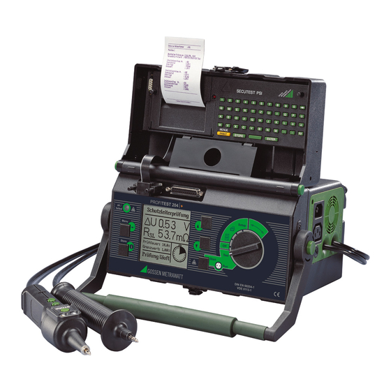
- Page 1 Operating Instructions PROFITEST 204+, 204L+, 204HP, 204HV 3-348-781-03 Test Instrument for EN 60204 / DIN VDE 0113 21/3.13 Test instrument may only be operated under supervision of a qualified electrician!
- Page 2 10 11 Connector Panel PROFITEST 204+: Basic Instrument GMC-I Messtechnik GmbH...
- Page 3 16 Carrying handle and tilt stand 17 Test probe with integrated controls Remote Control 18 Test probe with integrated fuse PROFITEST 204+: Test Probes 19 Key for saving measurement value 20 Key for starting protective conductor measurement 21 Key for starting insulation measurement...
- Page 4 As opposed to high-voltage pistols without switch, the high-voltage switch- ing pistol is identified with a red clamping ring on the connector cable un- derneath the handle. PROFITEST 204 HP/HV High-Voltage Module 8 Recessed safety test probe Connector Panel GMC-I Messtechnik GmbH...
- Page 5 • Chapter 2: Safety Features and Precautions The free PC starter software WinProfi* is used for communication with your PROFITEST 204+ test instrument. WinProfi is available on • Chapters 3.1 and 3.2: Inserting and activating the SI Module our homepage with the following content and functions: •...
-
Page 6: Table Of Contents
4.2.2 Start the Test ................30 2.1.2 Symbols in the Operating Instructions ..........10 Leakage Current Test ..............31 2.1.3 Symbols which Appear at the PROFITEST 204+ Display ....10 4.3.1 Configuring Test Parameters ............31 2.1.4 Symbols which Appear at the Display of the 4.3.2 Start the Test ................31... - Page 7 11.1 Replacing Fuses ................66 11.1.1 Replacing the Mains Fuse ............. 66 11.1.2 Replacing the Measuring Circuit Fuse in the Test Probe at the PROFITEST 204+ ..........66 11.2 Housing and Test Probes .............. 66 11.3 PROFITEST 204+ Measurement Cables ........66 11.4...
-
Page 8: Applications
Applications PROFITEST 204+ PROFITEST 204L The PROFITEST 204+ test instrument is used for quick and safe The PROFITEST 204L test instrument has been furnished with testing of electrical and electronic equipment and systems at an extra-long measurement and control cable, allowing for machinery in accordance with DIN VDE 0113/EN 60204-1. -
Page 9: Safety Features And Precautions
Safety Features and Precautions The PROFITEST 204+ basic instrument and the PROFITEST 204HP and HV high-voltage modules may not be operated: This instrument fulfills the requirements of the applicable Euro- • If visible damage is apparent pean and national EC guidelines. We confirm this with the CE •... -
Page 10: Meanings Of Symbols
Meanings of Symbols 2.1.1 Symbols on the Instrument 2.1.3 Symbols which Appear at the PROFITEST 204+ Display The symbols on the instrument have the following meanings: Warning concerning a point of danger, e.g. voltage at the test probe is greater than 25 V... -
Page 11: Symbols Which Appear At The Display Of The Profitest 204Hp/Hv High-Voltage Module
I , because the last measured value is always displayed. Instrument is defective! / Transmission between PROFITEST 204+ and 204HP/HV interrupted. Excessive temperature inside the test instrument (high-voltage test) Allow instrument to cool down for approx. 10 minutes. -
Page 12: Special Safety Precautions And Instructions For The Profitest 204Hp/Hv High-Voltage Module
Special Safety Precautions and Instructions for the PROFITEST 204HP/HV High-Voltage Module Precautions for the prevention of unauthorized activation: General Safety Precautions • Key Switch • Integrated signal lamps identify the operating status of the test in- strument. Precautions for the prevention of unintentional activation: •... - Page 13 Attention! Danger: High-Voltage! Observe regulations set forth in EN 50191, The test probe is made accessible after the trigger at “Erection and operation of electrical test equipment”. the high-voltage pistol with switch has been pulled to its initial mechanical limit stop. High-voltage is not switched to the test probe until the trigger is pulled beyond this position, assuming the instrument is in the “ready to activate”...
-
Page 14: Initial Start-Up
3.1.1 Mounting the High-Voltage Module to the Basic Instrument The HP or the HV high-voltage module must be mounted to the PROFITEST 204+ test instrument before initial start-up. When correctly mounted, reliable data exchange is assured between the two devices by means of LED transmission (see chapter 3.7.4, “Performing the Self-Test”). -
Page 15: The Key Switch
3.1.2 The Key Switch Caution: Danger! : Ready for Activation, The key switch protects the instrument against unauthorized use. Keep the key in a safe place to which only authorized personnel • The menu used to start the voltage test has been opened and have access. -
Page 16: Mounting The Instruments To The Optional Caddy
Mounting the Instruments to the Optional Caddy Item Designation Qty. Order No. ➭ Place the unit (consisting of the basic unit and the high-voltage Platform 3-117-193-01 module) onto the caddy platform (1) such that the lid of the Cable Reel 3-326-653-01 basic unit can still be opened. -
Page 17: Connecting The Profitest204+ To 230 V Mains Power
Connecting the PROFITEST 204+ to 230 V Mains Power ➭ Connect the test instrument to 230 V mains power with the attached mains connection line (connection 22 at the instru- ment). = 230 V If an earthing contact outlet is unavailable, or if only a 3-phase L –... -
Page 18: Operating Software
➭ Operating Software Press the STORE key in order to query online help: Measuring and testing is quick and easy with the PROFITEST 204+. The integrated operating software informs the user concerning all necessary operating procedures, errors and measuring results STORE etc., regardless of the selected measuring function. -
Page 19: Setup
Setup 3.7.1 Adjusting Contrast and LCD Illumination Various basic settings can be configured for the test instrument Contrast can be increased or reduced with this function. with the selector switch in the SETUP position. Furthermore, illumination can be activated or deactivated. (Only for devices with electroluminescence lighting) SETUP SETUP... -
Page 20: Setting Time And Date
3.7.2 Setting Time and Date 3.7.3 Configuring the Signal Generator The test instrument’s internal clock can be set with this function. If “Measuring mode” or “On” is selected, various acoustic The clock continues to run, even after the instrument has been signal sequences are generated during operation of the disconnected from mains power. -
Page 21: Performing The Self-Test
This portion of the self-test examines the calibration subassembly. Even if the CAL checksum is OK, this does not mean that the PROFITEST 204+ need not be calibrated in accordance with the prescribed schedule. If this portion of the self-test is failed, the instrument must be returned to the manufacturer for re-calibration. - Page 22 LCD Test In the following two tests, neighboring horizontal and vertical START elements at the LCD are activated separately. If individual cells do Continue testing. not become active, send the instrument to an authorized service center for repair. START Continue testing. Note The LEDs must first blink, and the relays must be switched before they can be checked off as OK.
-
Page 23: Uploading The Desired Language Or A Software Update
The software encompasses all of the functions required for establishing communica- tions between the PROFITEST 204+ and a PC. A program The program is added to your start menu after installation. description is contained in the online instructions included with the WinProfi software. - Page 24 B Prerequisites for Software-Update or Exchange of Data C Transmitting a Software Update to the Test Instrument ➭ Find the interface to which the PROFITEST 204+ is connected. Attention! Previously saved data are lost during the updating procedure. Save the measured values to your PC before.
- Page 25 D Organizing Report Data • Edit or transmit report templates ➭ Connect the test instrument directly with the PC via an appro- prate interface cable. Note Do not connect the PC to the SI module. • Send or receive a data file •...
-
Page 26: Testing Machines In Accordance With Din Vde 0113 And En 60 204
8, page 57. If voltage is present at the test probes after measurement has begun*, no measurement is performed. Interference voltage at test Setting Ranges for PROFITEST 204+ Parameters probes appears at the display, and a STOP signal is displayed simul- taneously. -
Page 27: Configuring Test Parameters
The limit value setting for protective conductor resistance is based upon the cross-section of phase conductor L and, if applicable, neutral conductor N, and not the cross section of protective conductor PE. This is necessary because cables with TEST phase conductor cross-sections of greater than 16 square mm are equipped with protective conductors of reduced cross- section, and selection on the basis of protective conductor cross- section would not be unequivocal. -
Page 28: Start The Test
4.1.2 Start the Test MENU Select the parameter. START Set the value. Note The test can only be started with the START key on the Proceed as follows in order to select the limit value: test instrument from the test parameters window (see picture on page 27). -
Page 29: Insulation Resistance Test
Do not touch the test probes during this measurement! A direct voltage of up to 1000 V is present between the Four nominal voltage ranges are included with the PROFITEST 204+ test probes. for this test: 100 V, 250 V, 500 V and 1000 V. These can be con- figured as test parameters, as is also the case with the allowable limit value for insulation resistance. -
Page 30: Configuring Test Parameters
4.2.1 Configuring Test Parameters 4.2.2 Start the Test Select a test voltage of 500 V for the main circuit, or 1000 V if required for extended testing. A lower test voltage can also be selected for testing voltage sensitive components. The allowable START limit value for insulation resistance can also be changed. -
Page 31: Leakage Current Test
Leakage Current Test 4.3.1 Configuring Test Parameters This test is required by DIN VDE 0701-0702. It can be used to The limit value (maximum leakage current) can be changed. test devices, machines and systems for the observance of limit values for leakage current (contact current). MENU Leakage current and voltage drop resulting from this current at a 2 kload are measured and displayed. - Page 32 STORE Press briefly: Store an event. Press and hold: Store an event and activate the entry field. Up to 15 characters can be entered to the entry field, or to the info field at the bottom left as a description for the measurement. See chapter 5.1.1 regarding data entry.
-
Page 33: Voltage Measurement (Protection Against Residual Voltage)
Testing for the absence of voltage is conducted with the • Voltage measurement is restarted from the menu PROFITEST 204+ by means of a voltage measurement which mea- • Voltage at the test probes climbs again to a value of greater sures discharge time as well. -
Page 34: Configuring Test Parameters
4.4.2 Start the Test TEST START Select the desired test. MENU Note Open the sub-menu. The voltage test can only be started with the START key on the test instrument. 4.4.1 Configuring Test Parameters The discharge period (the time during which the voltage value must STORE be reduced to a safe level of less than 60 V) can be set within a range of 0 to 9 seconds. -
Page 35: Voltage Test (Option: Profitest 204Hp/Hv)
Voltage Test ➭ Note Set the key switch to “I”. The PROFITEST 204+ must be used in combination with • The green signal lamps must light up. the PROFITEST 204HP/HP-2.5kV high-voltage module ➭ Select the voltage test with the keys. - Page 36 ➭ Select the desired values for test duration, test voltage, c) Shutdown Functions breaking current I and rise time (chapter 4.5.2, page 37). ➭ Short circuit the two high-voltage pistols. ➭ Pull the trigger at the marked high-voltage pistol with switch to Note its limit stop and hold depressed.
-
Page 37: Configuring Test Parameters
4.5.2 Configuring Test Parameters d) Signal Lamps Two lamps are arranged diagonally at the test instrument and are The following parameters can be configured with the green signal used to signal operating states. If both lamps go out when the lamps illuminated in the stand-by state: instrument is in the “ready to activate”... - Page 38 MENU Select the desired parameter. Adjust to the desired value. Test Voltage Time Test Decline* Rise * Constant = 0.1 s Test Time GMC-I Messtechnik GmbH...
-
Page 39: Test Sequence
4.5.3 Test Sequence Attention! Danger: High-Voltage! Make sure that all points of access to the danger zone Touch neither the test probes nor the device under test have been secured before testing is started, and that no during the voltage test! persons remain within the danger zone when the system A life endangering high-voltage of up to 5 kV is present at is made ready for activation. - Page 40 Storing Measured Values to Memory Premature Interruption of the Test After the test sequence has been completed, the last measured The test can be interrupted prematurely at any time by releasing values for U and I remain at the display. These results can be the trigger at the high-voltage pistol with switch.
-
Page 41: Pulse Control Mode
4.5.4 Pulse Control Mode 4.5.5 Ending the Voltage Test ➭ The pulse control mode is recommended for troubleshooting Release the triggers at the high-voltage pistols. (locating the point of flashover). ➭ Press the MENU key. Breaking current I is set to a fixed value of approximately ➭... -
Page 42: Processing, Transmitting And Deleting Data
• Data Transmission Measurement data (the entire contents of the memory at the PROFITEST 204+) can be transmitted to a PC with this function, where they can be subsequently analyzed, e.g. with the programs WinProfi, PS3 or EXCEL. Data records which have Select a number. -
Page 43: Entering A Description
SECUTEST SI+). ➭ Select the new system and press the MENU key. – Entry with the Keys at the PROFITEST 204+ The copied text appears and can be edited as desired. 5.1.3 Deleting a Description Select letters, numbers or characters. -
Page 44: Data Processing (Viewing Measured Values)
Data Processing (viewing measured values) Data Reorganization Measured values can be viewed, and individual measurements 5.3.1 Deleting Recorded Data can be deleted if desired. Data from individual systems which have already been printed out, and existing systems which contain no data, can be deleted with this function. -
Page 45: Memory Test
5.3.2 Memory Test Clearing Memory This command deletes stored data from all existing systems. Full Memory is tested for errors with this function. Errors can be memory capacity is made available in this way. corrected in some cases. Follow the instructions which appear at the display. -
Page 46: Data Transmission
Measurement data (the entire contents of the memory at the C Transmitting Data from the Test Instrument to the PC PROFITEST 204+) can be transmitted to a PC with the function ➭ PC: Select Receive data in the File menu. - Page 47 D Transmitting Data from the PC to the Test Instrument ➭ PC: Select Transmit data in the File menu. Follow the instructions which appear at the monitor. ➭ PC: Enter the name of the file whose data are to be transmitted to the test instrument: NAME.DAT ➭...
-
Page 48: Printing, Uploading And Creating Reports
Printing, Uploading and Creating Reports Print Values (PSI) / Print a Report The test instrument’s report functions can be activated by setting the function selector switch to the Printer position. The following functions are available: • Print Values (PSI) (only in conjunction with SECUTEST PSI): Measured values from a selected system can be read out via the serial interface and printed out at the PSI module (optional) Select the desired command. -
Page 49: Selecting A Form For Report Printing
Selecting a Form for Report Printing Selection can be made from amongst three previously stored report or print-out forms. Data are then laid out in accordance with the selected form, and are read out to an external printer. Note Three report forms are included with the instrument as a standard feature. -
Page 50: Uploading A Report Form
WinProfi software, and can be uploaded to the ➭ Install the software as described in chapter 3.7.5, part A, if not PROFITEST 204+. WinProfi software provides the user with a high already installed. performance editor to this end. - Page 51 C Uploading Report Forms from the PC to the Test Instrument – Printing the Report ➭ Select the desired printer in Windows. The standard printer is Note: Forms can only be uploaded from the PC to the test instru- always used. Printer settings can be changed to suit your ment if they are located in the same directory as specific needs with the printer setup function in the System the WinProfi program files.
- Page 52 – Print the report to a file and edit. ➭ Select the Output to File function instead of Output to printer. The NAME.XXX file is created automatically (XXX stands for the system number, which is entered automatically). ➭ Start the WinProfi editor from the Windows start menu. ➭...
-
Page 53: Report Form Generating Program
1: Max. voltage drop at the protective conductor @NAME Prints the device ID at the corresponding position 2: Max. protective conductor resistance value (PROFITEST 204+ or OEM designation). 3: Test duration for protective conductor test 4: Limit value for protective conductor voltage drop @SER Prints the device serial number at the corresponding position in the following format: M 1234 5678. -
Page 54: Report Layouts
Voltage measurement: @RESULT ( ) This code adds the word “bad” to the text, if at 1: Voltage at the test probes least one bad value has been measured for a given 2: Frequency type of measurement, see @VAL ( ). 3: Time in seconds until discharge to less than 60 V @RESULT (0) This code adds the word “bad”... -
Page 55: Characteristic Values
Characteristic Values PROFITEST 204+ Measured Measuring Nominal Range Reso- Nominal Voltage Open- Nominal Short- Internal Measuring Intrinsic Uncertainty Overload Quantity Range of Use lution Circuit Current Circuit Resis- Uncertainty Capacity Duration Voltage Current tance 100 0 ... 85 m... - Page 56 PROFITEST 204HP Nominal Range of Reso- Measuring Intrinsic Uncertainty lution Uncertainty (5% rdg. + 5 digits) (2.5% rdg. + 5 digits) Test Voltage 250 V ... 2.00 kV U AC 10 V (7% rdg.+ 5 digits) (5% rdg. + 5 digits) Measured Qty.
-
Page 57: Setting Ranges For Parameters And Standard Values Per Din Vde
Setting Ranges for Parameters and Standard Values per DIN VDE PROFITEST 204+ Measurement Parameters Charact. Cross-Section Lower Limit Standard Value Upper Limit Special Setting Options Protective Conductor Mea- Test duration 10 s 120 s Continuous measurement surement 1.34 Limit value for protective 1.5 square mm... - Page 58 PROFITEST 204HP-2.5kV Load Impedance ohmic Parameter Lower Limit Standard Value Upper Limit Special Setting Options Nominal Ranges of Use Test Duration 120 s Continuous Line Voltage 207 V ... 253 V Test Voltage 250 V 1 kV 2.5 kV or 2 x U Line Frequency 45 Hz ...
- Page 59 Electrical Safety Electromagnetic Compatibility (EMC) PROFITEST 204+ Safety Class 204: Product 204HP/HV: Standard EN 61326-1:2006 per IEC 61010-1 / EN 61010-1 / VDE 0411-1 Interference Emission Class Line Voltage 230 V EN 55022 Test Voltage, 204 5.55 kV 50 Hz...
-
Page 60: Data Interfaces
The included software allows for the convenient generation of reports forms at the PC, and uploading to the test instrument. 9.1.2 Interface Definition and Protocol The PROFITEST 204+ interface complies with the RS 232 Parallel Interface (printer port) standard. Any commercial printer with a CENTRONICS parallel port can be Technical Data: connected to this interface (4). -
Page 61: Signals / Error Messages, Causes And Remedies
Signals / Error Messages, Causes and Remedies Signal / Error Message Meaning / Cause Remedy PROFITEST 204+ Basic Instrument Test Sequence The stopwatch is displayed during protective conductor measurement. The falling voltage value is continuously displayed until residual voltage has reached a value of less than 60 V. - Page 62 Signal / Error Message Meaning / Cause Remedy Warning for leakage current test: Voltage may not exceed 250 V. Indication that test current is less than 10 A. Warning regarding a source of danger, e.g. voltage at the test probe is greater than 25 V This symbol appears after the measured voltage value has been frozen at the display (see chapter 4.4, page 33).
- Page 63 Check the data record. The printer is functioning incorrectly. Check the connection between the printer and the PROFITEST 204+, and then press the START key. The printer is functioning correctly. Press the MENU key in order to abort printing. The printer does not function.
- Page 64 Green signal lamps are not illuminated – Defective signal lamp – Replace signal lamp – Faulty data exchange between PROFITEST 204+ and 204HP/HV – Refer to following error message: “Defective instrument!” – Defective signal lamp – Replace signal lamp, see chapter 11.5.2, page 67 Red signal lamps are not illuminated Current measured during the test was capacitive to a given extent.
- Page 65 Signal / Error Message Meaning / Cause Remedy High-voltage module can be switched on. High-voltage present at the test probes during measurement Do not touch the test probes! The specified limit value I has been exceeded. The current limiting function has switched the instrument to the “standby” mode. Test completed successfully: residual voltage less than 25 V Continuous operation with high power Allow the instrument to cool down for...
-
Page 66: Maintenance
Safety features should be inspected and documented at least once a 11.1.2 Replacing the Measuring Circuit Fuse in the year by the repair department at GMC-I Service GmbH to assure flawless Test Probe at the PROFITEST 204+ functioning and efficiency. 11.1... -
Page 67: Profitest 204Hp/Hv Test Cables
12 to 15V / 2W with BA9s base, e.g. OSRAM 11.5.1 Cleaning the Transmitter and Receiver Diodes Miniwatt T10 no. 3453B. ➭ If the PROFITEST 204+ basic instrument is operated for a lengthy Replace the reflector. period of time without a high-voltage module, the transmitter and ➭... -
Page 68: Replacing Bulbs At The External Signal Lamps
Remove the defective bulb from the bayonet fixture and install ➭ Establish a connection between a new bulb: 12 to 15V / 2W with BA9s base, e.g. OSRAM the PC and the PROFITEST 204+. Miniwatt T10 no. 3453B. ➭ Switch both devices on. -
Page 69: Recalibration
11.7 Recalibration 11.8 Device Return and Environmentally Compatible Disposal The respective measuring task and the stress to which your mea- The instrument is a category 9 product (monitoring and control suring instrument is subjected affect the ageing of the components instrument) in accordance with ElektroG (German Electrical and and may result in deviations from the guaranteed accuracy. -
Page 70: Appendix
Appendix 12.1 Checklist for the High-Voltage Test ➭ Protective Measures for Personnel Attention in TN systems! In these systems, the protective conductor is connected with ➭ Switch the machine off and secure against switching back on. the neutral conductor in the terminal box. High-voltage is ➭... -
Page 71: Minimum Display Values In Consideration Of Operating Error
12.2 Minimum Display Values 12.3 List of Abbreviations in Consideration of Operating Error Table for the calculation of minimum display values for protective Abbreviation Meaning conductor resistance, insulation resistance and differential current I Contact current for leakage current test in consideration of instrument operating error: U Voltage drop during protective conductor test I [mA]... -
Page 72: Index
12.4 Index ELEKTROmanager ....9 Breaking current ETC ....... 9 Mains connection . - Page 73 Residual voltage WinProfi determination of value ... . 33 installation and program start ..23 indication ... . . 11, 34, 61, 65 transmission and print-out of report data .
-
Page 74: Repair And Replacement Parts Service Calibration Center And Rental Instrument Service
Repair and Replacement Parts Service We offer a complete range of expertise in the field of metrology: from test reports and proprietary calibration certificates right on up to Calibration Center * DAkkS calibration certificates. and Rental Instrument Service Our spectrum of offerings is rounded out with free test equipment management. - Page 75 GMC-I Messtechnik GmbH...
- Page 76 Edited in Germany Subject to change without notice A pdf version is available on the internet. Telefon+49 911 8602-111 GMC-I Messtechnik GmbH Telefax +49 911 8602-777 Südwestpark 15 E-Mail info@gossenmetrawatt.com 90449 Nürnberg • Germany www.gossenmetrawatt.com...
Need help?
Do you have a question about the PROFITEST 204 and is the answer not in the manual?
Questions and answers