
Related Manuals for Gossen MetraWatt PROFITEST MASTER IQ Series


Summary of Contents for Gossen MetraWatt PROFITEST MASTER IQ Series
- Page 1 Operating Instructions PROFITEST IQ Series ASTER PROFITEST TECH XTRA 3-447-153-03 IEC 60364-6, EN 50110-1 1/2.23...
-
Page 2: Table Of Contents
10.5 Measured Value Display and Memory ....36 13.1.1 Measurement with Positive Half-Waves (PROFITEST MTECH+ IQ, PROFITEST MXTRA 10.6 Help Function.............38 IQ only) ............56 10.7 Setting Parameters or Limit Values using RCD 13.2 Evaluation of Measured Values......56 Measurement as an Example ......39 Gossen Metrawatt GmbH... - Page 3 25.4 Periodic Testing per DGUV V 3 (previously BGV A3) Measurement with Accessory Sensors......81 – Limit Values for Electrical Systems and 18.1 Current Measurement with Current Clamp Operating Equipment ........104 Sensor ...............81 25.5 Bibliography .............105 25.6 Internet Addresses for Additional Information ..105 Gossen Metrawatt GmbH...
-
Page 4: Safety Instructions
Testing for the absence of voltage is only permissible with a suitable voltage tester or voltage measuring system which ful- fills the requirements specified in DIN EN 61243. Gossen Metrawatt GmbH... -
Page 5: Applications
✓ ✓ ✓ Voltage drop (U) ✓ ✓ ✓ Nor does Gossen Metrawatt GmbH accept any liability for data Standing-surface insulation Z ✓ ✓ ✓ Meter startup (kWh test) loss. ✓... -
Page 6: Documentation
– section 19, “Special Functions – EXTRA Switch Position”, on page 81 Measuring current – section 20, “Test Sequences (Automatic Test Sequences) – Nominal current AUTO Function”, on page 95 Test current Further interesting information: section 21, “Maintenance”, on page 97. Voltage: Line voltage frequency Gossen Metrawatt GmbH... -
Page 7: The Instrument
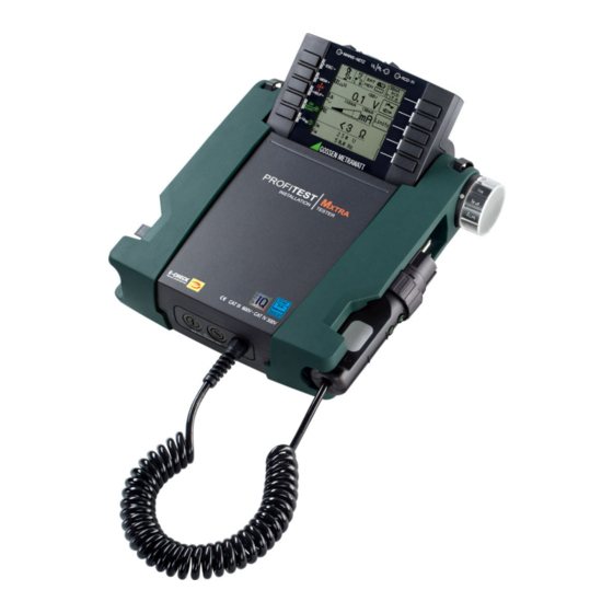
The Instrument Meanings of Symbols on the Instrument Warning concerning a point of danger Scope of Delivery (attention, observe documentation!) Standard scope of delivery for PROFITEST MASTER IQ series: Protection category II device 1 Test instrument 1 Compact battery pack (Z502H) -
Page 8: Instrument Overview
* Can only be switched on with the key on the instrument 11 Contact surfaces for finger contact Accessories: 12 Test plug holder A PRO-HB (Z501V) test probe and measuring adapter holder – 13 Fuses can be purchased separately 14 Holders for test probes (8) Gossen Metrawatt GmbH... - Page 9 Two replacement fuses are also located under the battery com- plug or at the control panel. Exception: If the instrument is partment lid. switched off, it can only be switched on by pressing the key at the control panel. Gossen Metrawatt GmbH...
-
Page 10: Technical Data
Z502R charger Charging time Z502R charger: approx. 2 hours * * Maximum charging time with fully depleted batteries. A timer in the charger limits charging time to no more than 4 hours. Gossen Metrawatt GmbH... -
Page 11: Characteristic Values For Profitest Mtech+ Iq
200 k … 999 k EXTRA 2.3 mA at 230 V 0.01 M 1.00 M … 9.99 M 1.00 M … 9.99 M ±(|10% rdg.|+2d) ±(|5% rdg.|+3d) 0.1 M 10.0 M … 30.0 M 10.0 M … 30.0 M Gossen Metrawatt GmbH... - Page 12 < 500 V As of firmware version 3.4.4: 15 mA test current only applies if the RCD is set for I = 30 mA. Otherwise test current = ½ × I of the preselect- ΔN ΔN ed RCDs. Gossen Metrawatt GmbH...
-
Page 13: Characteristic Values For Profitest Mpro Iq, Profitest Mxtra Iq
EXTRA 2.3 mA at 230 V 1.00 M … 9.99 M 0.01 M 1.00 M … 9.99 M ±(|10% rdg.|+2d) ±(|5% rdg.|+3d) 10.0 M … 30.0 M 0.1 M 10.0 M … 30.0 M Gossen Metrawatt GmbH... - Page 14 Input impedance of the signal input at the test instrument: 800 k Up to firmware 3.4.4:where f < 45 Hz => U < 253 V As of firmware 3.6.0:where f < 45 Hz => U < 500 V Gossen Metrawatt GmbH...
- Page 15 < 10 or clamp meter current > 500 μA E.sel 100 and R 100 Where R Where d = 20 m Where d = 2 m Only where RANGE = 20 k Only where RANGE = 50 k or AUTO Gossen Metrawatt GmbH...
-
Page 16: Operating And Display Elements
Memory half full Connection Test – Mains Connection Test ( section 6.4) Attention! Connection OK L and N reversed The mains connection test may not be used to test sys- tems or system components for the absence of voltage! Gossen Metrawatt GmbH... -
Page 17: Led Indications, Mains Connections And Potential Differences
Phase conductor L and protective conductor PE reversed Is dis- All except for U played Neutral conductor interrupted (with probe only) Is dis- All except for U L and N are connected to the phase conductors. played Gossen Metrawatt GmbH... - Page 18 Conductor L2 missing Is displayed (3-phase measurement) Conductor L3 missing Is displayed (3-phase measurement) Conductor L1 to N Is displayed (3-phase measurement) Conductor L2 to N Is displayed (3-phase measurement) Conductor L3 to N Is displayed (3-phase measurement) Gossen Metrawatt GmbH...
- Page 19 Is dis- Battery charge level ≥ 50% played Is dis- L-PE Battery charge level ≥ 30% played N Is dis- Battery charge level ≥ 15% Setup, played EXTRA, Is dis- Battery charge level ≥ 0% played SENSOR Gossen Metrawatt GmbH...
- Page 20 Externally accessible fuse is blown. The voltage ranges remain functional even if fuses have blown. All except for U Special case, R : Interference voltage during measurement may result in a blown fuse. Remedy: Replace fuse as described in section 21.2. Gossen Metrawatt GmbH...
- Page 21 OFFSET value is greater than the measured value at the consuming sys- EXTRA U tem. OFFSET measurement is not sensible. Remedy: Check system. Contact problem or blown fuse Remedy: Check test plug or measuring adapter for correct seating in the E(bat) test plug, or replace the fuse. Gossen Metrawatt GmbH...
- Page 22 If specified touch voltage U is exceeded: and R : User is prompted to switch to the 15 mA wave. L-PE L-PE alternative only: User is prompted to reduce the measuring range (reduce current.) Gossen Metrawatt GmbH...
- Page 23 15 mA only possible in 1 k and 100 ranges! EXTRA RCM With RCM: Types AC, F, B+ and EV/MI are not possible. N Measurement with half-wave or DC is not possible in IT systems. EXTRA RCM Gossen Metrawatt GmbH...
- Page 24 Test measurement: The test has not been passed. EXTRA I The leakage current measuring adapter is defective. Contact our repair service department. Test measurement: EXTRA I Check the fuse in the leakage current measuring adapter. Gossen Metrawatt GmbH...
- Page 25 The database in the instrument’s internal memory is empty after database transfer has been interrupted. Remedy: Reduce the size of the database in IZYTRONIQ or transfer the database without measured values (Transmit Structure key), if measured values already exist. Gossen Metrawatt GmbH...
-
Page 26: Operation
(Z502H/) or by inserting fully charged, commercially may result in overheating and thus deformation and ex- available rechargeable batteries or new batteries. See section 7.1, plosion when charging them in the instrument. “Power Supply”, on page 26. Gossen Metrawatt GmbH... -
Page 27: Instrument Settings
Language for user interface Duty cycle DB MODE submenu for display illumination / tester Brightness/contrast submenu Default settings Display Illumination On-time Test Instrument On-Time Return to submenu No automatic shutdown, continuously on Gossen Metrawatt GmbH... - Page 28 Return to submenu Select time Apply settings Increase hours Decrease hours Increase minutes Decrease minutes Increase seconds Decrease seconds Set date Return to submenu Select date Apply settings Increase Decrease Increase Decrease month month Increase Decrease year year Gossen Metrawatt GmbH...
- Page 29 These can then be edited in the are invalid. The measurement results cannot be saved to report generating program and transferred back to the test instru- memory. ment if required. ➭ Press ESC in order to return to the main menu. Gossen Metrawatt GmbH...
- Page 30 The inspector cannot be changed. If an inspector’s name is incorrect, it can be deleted and a new inspector can be created with the correct name. Changes are not retroactive. Deleted inspectors are retained for tests which have already been performed. Gossen Metrawatt GmbH...
-
Page 31: Database
The test instrument and the PC must be connected with a USB Location tree cable in order to transfer structures and data. Property Note Building The rotary selector switch may not be set to the “U” posi- tion during data transmission. Floor Room E-tree (electrical tree) Gossen Metrawatt GmbH... - Page 32 > Enter complete ID number. Search for text. > Enter full text (complete word). Search for ID number or text. Continue searching. Edit menu Cursor LEFT: Select an alphanumeric character. Cursor RIGHT: Select an alphanumeric character. ENTER: accept an individual character. Gossen Metrawatt GmbH...
-
Page 33: Creating Structures (Example For Electrical Circuit)
Select the desired object from the list with the keys and acknowledge with the key. Depending upon the profile selected in the test instrument’s SETUP menu (see section 8), the number of object types may be limited, and the hierarchy may be laid out differently. Gossen Metrawatt GmbH... -
Page 34: Searching For Structure Elements
➭ Switch to page 2 by pressing the key shown here: ... the first match is displayed. ➭ Display the measurement data Further matches can be found by selecting by pressing the key shown here: the icon shown at the right. Gossen Metrawatt GmbH... -
Page 35: Use Of Barcode Scanners And Rfid Readers
Previously selected parameters in the database are not used for the measurement. Use of Barcode Scanners and RFID Readers Search for an Already Scanned Barcode The search can be started from any switch setting and menu. Gossen Metrawatt GmbH... -
Page 36: General Information On Measurements
(see also section 7). Touch voltage which is induced by test current is monitored for each measuring sequence. If touch voltage exceeds the limit Gossen Metrawatt GmbH... -
Page 37: Help Function
In a system including an RCCB, the RCCB is tripped during touch voltage measurement without RCCB trip- ping (automatic Z measurement), insofar as N and PE are reversed. Gossen Metrawatt GmbH... -
Page 38: Setting Parameters Or Limit Values Using Rcd Measurement As An Example
6 The setting value is not permanently accepted for the respec- ✓ tive measurement until is pressed, after which the display is returned to the main menu. You can return to the main menu ✓ by pressing ESC instead of , without accepting the newly selected value. Gossen Metrawatt GmbH... -
Page 39: Freely Selectable Parameter Settings Or Limit Values
Observe the predefined limits for the new setting value. Enter any places to the right of the decimal point as well. Note Observe the predefined limits for the new setting value. Enter any places to the right of the decimal point as well. Gossen Metrawatt GmbH... -
Page 40: 2-Pole Measurement With Rapid Or Semiautomatic Polarity Reversal41
N instrument or the test plug. L-PE L1-PE L1-N L1-PE N-PE L2-PE L2-N L2-PE L1-PE L3-PE L3-N L3-PE L2-PE L1-L2 N-PE L3-PE L2-L3 L1-N L+N-PE L1-L3 L2-N L1-N L3-N L2-N L1-L2 L3-N L2-L3 L1-L2 L1-L3 L2-L3 L1-L3 Gossen Metrawatt GmbH... -
Page 41: Measuring Voltage And Frequency
If (mains) voltage is displayed for UL-PE, then the phase is located where L appears on the con- nector. If (mains) voltage is displayed for N-PE, then the phase is located where N appears on the connector. Gossen Metrawatt GmbH... - Page 42 Voltage Polarity If the installation of single-pole switches to the neutral conductor is prohibited by the standards, voltage polarity must be tested in order to assure that all existing single-pole switches are installed to the phase conductors. Gossen Metrawatt GmbH...
-
Page 43: Testing Rcds
30% residual current (if no bias current pole adapter. Suppression of RCD tripping by means of occurs within the system). bias magnetization with direct current is only possible via a country-specific plug insert, e.g. SCHUKO, or the 3- pole adapter. Gossen Metrawatt GmbH... - Page 44 Negative/positive half-wave Negative/positive direct current X times tripping current: 1, 2, 5 (I max. 300 mA) N Connection: Without/with probe System type: TN/TT, IT Touch voltage: < 25 V, < 50 V, < 65 V Time to trip: Gossen Metrawatt GmbH...
- Page 45 RCCB. However, the trip limit may be test instrument may blow, and/or the test instrument may be exceeded as a result of leakage current in the measuring circuit, damaged. e.g. due to interconnected consumers with EMC circuit, e.g. fre- quency converters or PCs. Gossen Metrawatt GmbH...
- Page 46 I must be calculated from N Negative/positive half-wave the measured values. Negative/positive direct current The faster, more simple measuring method should thus be taken advantage of (see section 12.1). Connection: Without/with probe System type: TN/TT, IT Gossen Metrawatt GmbH...
-
Page 47: Testing Rccbs With 5 × I N
Set Parameter – 5 Times Nominal Current X times tripping current: 5 times tripping current Note The following restrictions apply to the selection of tripping current multiples relative to nominal current: 500 mA: 1 × I , 2 × I N N Gossen Metrawatt GmbH... -
Page 48: Testing Of Special Rcds
RCCB can be executed with this test in order to assure that the RCCB is not saturated by the pulsating direct current so that it no longer trips. Gossen Metrawatt GmbH... -
Page 49: 12.3.2 Prcds With Non-Linear Type Prcd-K Elements
Time to trip t : tripping test with nominal residual current I N (the PRCD-K must be tripped at 50% nominal current) • Tripping current I for testing with rising residual current I Select Measuring Function N Connection Gossen Metrawatt GmbH... -
Page 50: Srcd, Prcd-S (Schukomat, Sidos Or Comparable)
180°. The longer of the two tripping times is decisive regard- ing the condition of the tested RCCB. Start Measurement Set Parameter – Start with Positive or Negative Half-Wave Waveform: 180°: Start with neg. half-wave 0°: Start with pos. half-wave Negative direct current Positive direct current Gossen Metrawatt GmbH... -
Page 51: Testing Residual Current Circuit Breakers In Tn-S Systems
I . In this case as well, the limit value must be appropriately N adjusted. Note The RCD parameter setting for selective RCCBs is not suitable for type G RCCBs. Gossen Metrawatt GmbH... -
Page 52: Testing Of Rcd Protection In It Systems With High Cable Capacitance (E.g. In Norway)
Set Parameter – Time to Trip Time to trip 6 mA 10.0 s 60 mA 0.3 s 200 mA 0.1 s Note The RDC-DD is tested with nominal residual currents of 6 to 200 mA. Start Measurement Gossen Metrawatt GmbH... - Page 53 Set Parameter – Time to Trip Time to trip 300 mA 0.04 s 6 mA 10.0 s 60 mA 0.3 s Note The RCMB is tested with nominal residual currents of 6 to 300 mA. Start Measurement Gossen Metrawatt GmbH...
-
Page 54: Testing Of Breaking Requirements For Overcurrent Protective Devices, Measurement Of Loop Impedance And Determination Of Short-Circuit Current (Zl-Pe And Isc Functions)
Only AC measurements can be performed with the 2- pole adapter. Suppression of RCD tripping by means of bias magnetization with direct current is only possible via a country-specific plug insert, e.g. SCHUKO, or the 3- pole adapter (neutral conductor N required). Gossen Metrawatt GmbH... -
Page 55: Iq Only)
(fuse or circuit breaker) for a line voltage of 230 V after allowance has been made for maximum measuring error can be determined with the help of Table 6 on page 101 based on measured short-circuit current (corresponds to IEC 60364-6). Gossen Metrawatt GmbH... -
Page 56: Settings For Calculating Short-Circuit Current - Parameter Isc
10% max. Frequency of the applied voltage, “f ” is displayed if frequency f max. deviates from nominal frequency by 1% Tripping current (see data sheet for circuit breakers / fuses) % Test instrument intrinsic error Gossen Metrawatt GmbH... -
Page 57: Measuring Supply Impedance (Z L-N Function)
Test instrument intrinsic error Press the softkey shown at the left in order to switch back and forth between the country-specific plug insert, e.g. SCHUKO, and the 2-pole adapter. The selected connection type is displayed inversely (white on black). Gossen Metrawatt GmbH... - Page 58 HELP key. The table shows maximum permissible nominal current depen- dent on fuse type and breaking requirements. Key: I = breaking current, I = short-circuit current, I = nominal current, t = time to trip Gossen Metrawatt GmbH...
-
Page 59: Earthing Resistance Measurement (Function R )
(at nominal conditions of use), can be determined with the help of Table 2 on page 100. Intermediate values can be interpolated. Gossen Metrawatt GmbH... -
Page 60: Earthing Resistance Measurement - Mains Powered
❏ Test current waveform types. See section 15.4 through section 15.6 regarding advisable Performing Measurements parameters for the respective measurement and connection See section 15.7 through section 15.11. types. Performing Measurements See section 15.4 through section 15.6. Gossen Metrawatt GmbH... -
Page 61: Earthing Resistance, Mains Powered - 2-Pole Measurement With 2-Pole Adapter Or Country-Specific Plug (Schuko) Without Probe
The calculated earthing resistance thus includes operational earth conductor resistance as a safety factor. If the parameter is selected, steps 1 through 3 are executed automatically by the test instrument. Select Measuring Function Select Operating Mode Gossen Metrawatt GmbH... -
Page 62: Earthing Resistance Measurement. Mains Powered - 3-Pole Measurement: 2-Pole Adapter With Probe
Select Measuring Function Limit Value: > Limit Value R Select Operating Mode Start Measurement Connection Note The following diagram appears if the 2-pole adapter is connected incor- rectly. To be connected: 2-pole adapter and probe Gossen Metrawatt GmbH... -
Page 63: Earthing Resistance Measurement, Mains Powered - Measuring Earth Electrode Potential (U Function)
The calculated value is displayed at the display panel. R Select Measuring Function Start Measurement Select Operating Mode Select Measuring Range Connection Note The following diagram appears if the 2-pole adapter is connected incor- rectly. To be connected: 2-pole adapter and probe Gossen Metrawatt GmbH... -
Page 64: Earthing Resistance Measurement, Mains Powered - Selective Earthing Resistance Measurement With Current Clamp Sensor As Accessory
In order to prevent electric shock, keep the surface of the METRAFLEX clean and free of contamination. • Before use, make sure that the flexible current sensor, the con- To be connected: 2-pole adapter, clamp and probe nector cable and the electronics housing are dry. Gossen Metrawatt GmbH... - Page 65 Selective earthing resistance measured via clamp Clamp Total earthing resistance measured via probe, Probe comparative value Note The following diagram appears if the 2-pole adapter is connected incor- rectly. Gossen Metrawatt GmbH...
-
Page 66: Earthing Resistance Measurement, Battery Powered, "Battery Mode" - 3-Pole (Profitest Mpro Iq & Profitest Mxtra Iq Only)
The measurement cables must be well insulated in order to prevent shunting. In order to keep the influence of pos- sible coupling to a minimum, the measurement cables should not cross each other or run parallel to each other over any considerable distance. Gossen Metrawatt GmbH... -
Page 67: Earthing Resistance Measurement, Battery Powered, "Battery Mode" - 4-Pole (Profitest Mpro Iq & Profitest Mxtra Iq Only)
However, if the three measured values for earthing resistance dif- should not cross each other or run parallel to each other fer from each other, either the probe is not located in the neutral over any considerable distance. Gossen Metrawatt GmbH... - Page 68 5 meters each. ➭ Measured resistance values are displayed as a table, and then plotted graphically as depicted in “Earthing Resistance Mea- surement for a Large Scope Earthing System” on page 68. (Curve I). Gossen Metrawatt GmbH...
-
Page 69: Earthing Resistance Measurement, Battery Pow
➭ Connect the Z3512A current clamp sensor to jacks (15) and (16) at the test instrument. ➭ Attach the current clamp sensor to the earth electrode. Select Measuring Function Select Operating Mode The selected operating mode is displayed inversely: white battery icon against black background. Gossen Metrawatt GmbH... -
Page 70: Earthing Resistance Measurement, Battery Pow
➭ Connect the Z3512A current clamp sensor to jacks 15 and 16 at the test instrument. ➭ Attach the 2 clamps to an earth electrode (earth spike) at dif- ferent heights with a clearance of at least 30 cm. Gossen Metrawatt GmbH... -
Page 71: Earthing Resistance Measurement, Battery Pow
➭ Connect the probes, the auxiliary electrode and the electrode of Precipitation (earth electrode depth < 1.5 m) via the 4 mm banana plug sockets at the PRO-RE adapter. In doing so, observe labeling on the banana plug sockets. Gossen Metrawatt GmbH... - Page 72 = Edge length (m) of a square ground plate; a is replaced with the fol- lowing for rectangular plates: b x c, where b and c are the two sides of the rectangle. J = volume (cubic meters) of an individual foundation footing Gossen Metrawatt GmbH...
-
Page 73: Measurement Of Insulation Resistance
Lx-PE / N-PE / L+N-PE / Lx-N / Lx-Ly / AUTO* down voltage which occurs is displayed for U where x, y = 1, 2, 3 The constant test voltage function offers two options: * AUTO parameter (see section 10.9) Gossen Metrawatt GmbH... - Page 74 The test instrument uses continuously rising test voltage for this measuring function, up to the maximum selected voltage limit. The measuring procedure is started by pressing the ON/START ▼ key and runs automatically until one of the following events Gossen Metrawatt GmbH...
-
Page 75: Special Case: Earth Leakage Resistance (Reiso )
➭ Establish a conductive connection between the measuring electrode and the test probe and connect the measuring adapter (2-pole) to an earth contact, e.g. the earthing contact at a mains outlet or a central heating radiator (prerequisite: re- liable ground connection). Gossen Metrawatt GmbH... - Page 76 Start Measurement The limit value for earth leakage resistance from the relevant regulations applies. Gossen Metrawatt GmbH...
-
Page 77: Measuring Low-Value Resistance Of Up To 200 (Protective Conductor And Equipotential Bonding Conductor)
UL/RL LED lights up. Limit values can be selected within a range of 0.10 to 10.0 (editable). The limit value is displayed above the measured value. Gossen Metrawatt GmbH... -
Page 78: Measurement With Constant Test Current
The instrument’s batteries are exposed to excessive stress during insulation resistance measurement. For measurement with cur- rent flow in one direction, only press and hold the ON/START ▼ key as long as necessary for the measurement. Gossen Metrawatt GmbH... -
Page 79: Protective Conductor Resistance Measurement
Measurement results cannot be read and measurement automatically takes subsequently with the same or another polarity cannot be started until required waiting time into account before the symbol at the right appears. you can reactivate the PRCD and start the measurement over again. Gossen Metrawatt GmbH... -
Page 80: Measurement With Accessory Sensors
Attention! Danger: High-Voltage! Use only current clamp sensors which are specifically of- fered as accessories by Gossen Metrawatt GmbH. Other current clamp sensors might not be terminated with an output load at the secondary side. Dangerously high voltage may endanger the user and the device in such cases. -
Page 81: Special Functions - Extra Switch Position
19.9 on ✓ ✓ statuses at charging page 91 — stations per IEC 61851-1 Documentation of section fault simulations at 19.10 on ✓ — — PRCDs with the PRO- page 92 FITEST PRCD adapter Gossen Metrawatt GmbH... -
Page 82: Voltage Drop Measurement
Limit value per DIN VDE 0100-520: U < 4% between the distribution network and the consuming device (adjustable up to 10% in this case) Limit value per NIV: U < 5% Gossen Metrawatt GmbH... -
Page 83: Measuring The Impedance Of Insulating Floors And Walls (Standing Surface Insulation Impedance)
Do not touch the metal plate or the damp cloth with your bare hands. No more than 50% line voltage may be applied to these parts! Current with a value of up to 3.5 mA may flow! The measured value would be distorted as well. Gossen Metrawatt GmbH... -
Page 84: Testing Meter Startup With Earthing Contact Plug - Kwh Function
Evaluate Measured Value The measured value has to be evaluated after measurement has been completed: NOT OK In the event that “NOT OK” is selected, an error is indicated by the UL/RL LED which lights up red. Gossen Metrawatt GmbH... -
Page 85: Leakage Current Measurement With Pro-Ab Leakage Current Adapter As Accessory
(in the case of overranging) be manually cor- rected at the measuring adapter and the test instrument. Individual limit values can be adjusted after pressing the Limits function key. Exceeded limit values are indicated by the red limit value LED at the test instrument. Gossen Metrawatt GmbH... -
Page 86: Testing Insulation Monitoring Devices - Imd Function (Profitest Mxtra Iq Only)
IMD indicates that insulation resistance has been fallen short of. ➭ Display of measured values ➭ Evaluation query: Measurement OK? ➭ If evaluation is NOT OK: the UL/RL LED lights up red. ➭ Save: by pressing the soft key. Gossen Metrawatt GmbH... - Page 87 ON/START ▼ or ESC key to this end. The stopwatch is stopped and the evaluation window appears. NOT OK With the help of the key shown at the right (MW: measured value / PA: parameter), the setting parameters can be displayed for this measurement. Gossen Metrawatt GmbH...
- Page 88 – e.g. if plug connectors are disengaged – which are not protected against direct contact, maximum permissible discharge time is 1 second! Limit Values Set Limit Values U Limit Value: U % > Limit Value R Gossen Metrawatt GmbH...
-
Page 89: Intelligent Ramp - Ta+Id Function
Nom. res. current: 10 … 500 mA Type 1: RCD, SRCD, PRCD … Type 2: AC , A/F Nominal current: 6 … 125 A * Type B = AC/DC sensitive Touch voltage: < 25 V, < 50 V, < 65 V Gossen Metrawatt GmbH... -
Page 90: Testing Residual Current Monitors - Rcm Function ( Profitest Mxtra Iq Only)
In the event that NOT OK is selected, an error is indicated by the UL/ RL LED which lights up red. The measured value cannot be saved to memory and included in the test report until it has been evaluated. Gossen Metrawatt GmbH... -
Page 91: Checking The Operating Statuses Of Electric Vehicles At Charging Stations Per Iec 61851 ((Profitest Mtech+ Iq & Profitest Mxtra Iq)
01/05 key display corresponds to A/E (01 = A, 02 = B, 03 = C, 04 = D, 05 = E). Status variants can be skipped by pressing the I key at the test N instrument or the test plug. Gossen Metrawatt GmbH... -
Page 92: Prcd - Test Sequences For Documenting Fault Simulations At Prcds With The Profitest Prcd Adapter (Profitest Mxtra Iq Only)
— AUTO AUTO Semi-automatic change of fault simulations The test steps are displayed at the test instrument. Their mean- ings and the associated switch positions at the PROFITEST PRCD are listed in the above table. Gossen Metrawatt GmbH... - Page 93 PRCD-S, 3-phase: 18 test steps Simulation of PE to Phase (step 8) PRCD-K, single-phase: 5 test steps Contact ON Key at PRCD with Probe (step 10) Measurement of Protective Conductor Current with a Current Clamp Transformer (step 11) Gossen Metrawatt GmbH...
- Page 94 Test steps can be skipped during fault simulation by pressing the key at the test instrument or the test plug. N Simulation of PE to Phase (step 17) Measurement of Protective Conductor Current with a Current Clamp Transformer (step 18) Gossen Metrawatt GmbH...
-
Page 95: Test Sequences (Automatic Test Sequences) - Auto Function
RESS field. The parameters or details for the respective test When the test step is started once more, the parameter settings step must be entered here. specified in IZYTRONIQ are loaded again. ➭ Save your settings by clicking the icon. Gossen Metrawatt GmbH... - Page 96 (cursor left-right). Jumping to the next or the previous test step is possible using the separate scroll keys which then appear. The navigation menu can be exited again and the current test step can be displayed by pressing the ESC key. Gossen Metrawatt GmbH...
-
Page 97: Maintenance
Only original fuses from Gossen Metrawatt GmbH may be used (order no. 3-578-285-01 / SIBA 7012540.3.15 Query Current Status SI-EINSATZ FF 3.15/500 6.3X32). -
Page 98: Contact, Support And Service
Contact, Support and Service Gossen Metrawatt GmbH can be reached directly and simply – we have a single number for everything! Whether you require sup- port or training, or have an individual inquiry, we can answer all of your questions here:... -
Page 99: Disposal And Environmental Protection
Old devices, electrical or electronic accessories and waste batter- ies (including rechargeable batteries) used in Germany can be returned free of charge to Gossen Metrawatt GmbH or the service provider responsible for their disposal in compliance with applica- ble regulations, in particular laws concerning packaging and haz- ardous goods. -
Page 100: Appendix
2.38 3.00 2.82 3.00 2.86 3.50 3.30 3.50 3.34 4.00 3.78 4.00 3.82 4.50 4.25 4.50 4.30 5.00 4.73 5.00 4.78 6.00 5.68 6.00 5.75 7.00 6.63 7.00 6.71 8.00 7.59 8.00 7.67 9.00 8.54 9.00 8.63 Gossen Metrawatt GmbH... - Page 101 2.34 k 1.12 k 2240 3.18 k Example Display value of 90.4 A next lower value for circuit breaker characteristic B from table: 85 A nominal current (I ) of the pro- tective device: max. 16 A Gossen Metrawatt GmbH...
-
Page 102: At Which Values Should/Must An Rcd Actually Be Tripped? Requirements For Residual Current Devices (Rcd)
N Phase angle of 135° el 0.11 … 1.4 I N Pulsating direct current superimposed with 6 mA smooth, Max. 1.4 I + 6 mA N direct residual current Smooth direct current 0.5 … 2 I N Gossen Metrawatt GmbH... -
Page 103: Testing Electrical Machines Per Din En 60204 - Applications, Limit Values
Measurement Parameters Cross- Standard machines, can be performed with test instruments from the Section Value PROFITEST MASTER IQ series. Test duration 10 s Limit value 1.5 mm² 500 m Comparison of Tests Specified by the Standards Protective conductor resis- 2.5 mm²... -
Page 104: Bibliography
DGUV information, rules and regulations from German statutory accident insurance www.beuth.de VDE regulations, DIN standards, VDI directives from Beuth-Verlag GmbH www.bgetem.de BG information, rules and regulations from the trade associations, e.g. BG ETEM (trade association for en- ergy, textiles and electrical medical devices) Gossen Metrawatt GmbH... - Page 105 Gossen Metrawatt GmbH Prepared in Germany • Subject to change, errors excepted • PDF version available on the Internet All trademarks, registered trademarks, logos, product names and company names are the property of their respective owners. Phone: +49 911 8602-111...
Need help?
Do you have a question about the PROFITEST MASTER IQ Series and is the answer not in the manual?
Questions and answers