
Related Manuals for Gossen MetraWatt PROFITEST INTRO


Summary of Contents for Gossen MetraWatt PROFITEST INTRO
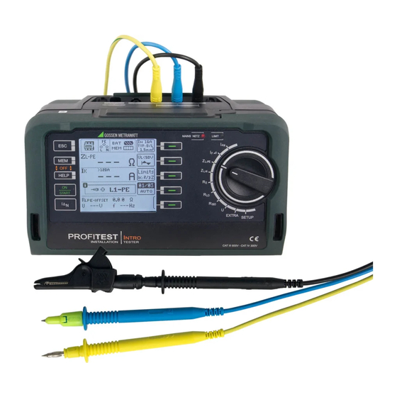
- Page 1 Operating Instructions PROFITESTI NTRO 3-349-840-03 Tester, DIN VDE 0100-600 / IEC 60364-6 4/11.17...
- Page 2 LCD Panel Rotary Selector Switch Guide for Guide for Carrying Strap Carrying Strap Setup Menu Control Panel Softkeys • Parameter selection MAINS/NETZ LED see below • Limit value specification • Entry functions Limit LED see below • Memory functions Fixed Function Keys ESC: Return from submenu /...
- Page 3 Batteries, Fuses Inserting the Battery Holder (side view) Battery Compartment Lid Battery Holder Battery Holder Fuses Contacts Battery Compartment Lid Contact Spring user interface Measuring Connections Test Probe with Remote Control, Option Z550A Optional Z503K Key for Measuring Measurement Point Illumination Z503L Test probe Measuring Point Illumination...
- Page 4 Overview of Device Settings and Measuring Functions Switch Picto- Device settings Connection test section 16 Display Panel Setting graph Measuring Functions Battery display descrip- Measuring function tion as of Measurement in Memory occupancy SETUP Brightness, contrast, time/date progress / stopped Language (D, GB, P), profiles (ETC, PS3, PC.doc) Default settings <...
-
Page 5: Table Of Contents
...29 10.1 Earth Resistance, Mains Operation – 2-Pole Measurement with Application ................ 5 KS-PROFITEST INTRO or Country-Specific Measuring Adapter Using Cable Sets and Test Probes ..........6 (Schuko) ..................30 Overview of Included Features ..........6 Measurement of Insulation Resistance ....... 32 Safety Features and Precautions ........ -
Page 6: Using Cable Sets And Test Probes
1 Battery pack Measurements per DIN EN 61010-031 may only be performed in 1 KS-PROFiTEST INTRO (Z503L) environments in accordance with measuring categories III and IV 1 Factory calibration certificate with the safety cap attached to the test probe at the end of the 1 Condensed operating instructions measurement cable. - Page 7 Safety Features and Precautions Meanings of Symbols on the Instrument Warning concerning a point of danger The electronic measuring and test instrument is manufactured (attention, observe documentation!) and tested in accordance with safety regulations IEC 61010-1/ EN 61010-1/VDE 0411-1. Protection class II device Safety of the operator, as well as that of the instrument, is only assured when it’s used for its intended purpose.
-
Page 8: Initial Start-Up
Initial Start-Up (Rechargeable) Battery Test If (rechargeable) battery voltage has fallen below the Installing or Replacing the Battery Pack allowable lower limit, the pictograph shown at the right appears. “Low Batt!!!” is also displayed along with a (rechargeable) battery symbol. The instrument does not function if Attention! the batteries have been depleted excessively, and no display Before opening the battery compartment, disconnect the... -
Page 9: Device Settings
Device Settings SETUP Menu Selection for Operating Parameters LED, LCD and acoustic signal test menu Battery test Display: date / time Display: automatic shutdown OFFSET, brightness/contrast menu of the tester after 120 s. Time, language, profiles Display: automatic shutdown Software revision level of display illumination after 20 s. - Page 10 Menu Selection for Operating Parameters LED and LCD test menu Menu Display: date / time Battery test Display: automatic shutdown Brightness/contrast menu of the tester after 60 s. Time, language, profiles Display: automatic shutdown Software revision level of display illumination after 15 s. Calibration date Enter and select a new inspector Current inspector...
- Page 11 PC, ETC always uses the same representation as the may differ from that of the test instrument (TXT or ID mode). PROFITEST INTRO. For this When transferring data from ETC at the PC to the test reason, the instrument, the test instrument always uses the same PROFITEST INTRO provides representation as ETC.
-
Page 12: General Notes
Note For systems with earthing contact sockets, connect the instru- In order to ascertain the R value for measurement ment to the mains with the KS-PROFITEST INTRO test probes OFFSET of U(ZLN): (Z503L) or with the PRO-Schuko measuring adapter (Z503K). -
Page 13: Measurement Value Display And Memory
• Impermissible line voltages (< 60 V, > 253 V / > 330 V / measurement with the Z503L KS-PROFITEST INTRO), PE > 440 V or > 550 V) for measurements which require line volt- appears (only after starting e test sequence). The MAINS LED blinks red as well. -
Page 14: Help Function
Help Function The following information can be displayed for each switch posi- tion and basic function after it has been selected with the rotary selector switch: • Wiring diagram • Measuring range • Nominal range of use and measuring uncertainty •... -
Page 15: Freely Selectable Parameter Settings Or Limit Values
Freely Selectable Parameter Settings or Limit Values 2-Pole Measurement with Fast or Semiautomatic Polarity Reversal In addition to fixed values, other values can be freely selected within predefined limits for certain parameters, if the symbol for Fast, semiautomatic polarity reversal is possible for the following the EDIT menu (3) appears at the end of the list of setting values. -
Page 16: Measuring Voltage And Frequency
PRO-Schuko measuring adapter (Z503K), and 2-pole measurement with the KS- PROFITEST INTRO (Z503L). The selected connection type is displayed inversely (white on black). Refer to section 5.8 regarding 2-pole measurement with fast or semiautomatic polarity reversal. -
Page 17: 3-Phase Measurement (Line-To-Line Voltage) And Phase Sequence
3-Phase Measurement (line-to-line voltage) and Phase Testing RCDs Sequence Testing of residual current devices (RCDs) includes: Connection • Visual inspection • Testing The included measure- ment cables (Z503L) are • Measurement required in order to con- Use the test instrument for testing and measurement. nect the instrument. -
Page 18: Measuring Touch Voltage (With Reference To Nominal Residual Current) With Nominal Residual Current And Tripping Test With Nominal Residual Current
Tripping of the RCCB must occur within 400 ms (1000 ms for selective RCDs) at nominal residual current. Important Notes • The PROFITEST INTRO permits simple measurements at all types of RCDs. Select RCD, SRCD, PRCD etc. Connection • Measurement must be executed at one point only per RCD (RCCB) within the connected electrical circuits. - Page 19 1) Measuring Touch Current Without Tripping the RCD 2) Tripping Test after the Measurement of Touch Voltage ➭ Press the I N Measuring Method The instrument uses a measuring current of only ⅓ nominal resid- The tripping test need ual current for the determination of touch voltage U which IN only be performed at...
-
Page 20: Special Tests For Systems And Rcds
Special Tests for Systems and RCDs 7.2.1 Testing Systems and RCCBs with Rising Residual Current (AC) for Type AC, A/F, B/B+ and EV, MI RCDs Touch voltage: Measuring Method The instrument generates a continuously rising residual current of (0.3 ... 1.3) within the system for the testing of RCDs. -
Page 21: Testing Rccbs With 5 I
7.2.3 Testing RCCBS with 5 7.2.4 Testing of RCCBs N Pulsating DC Residual Current Measurement of time to trip is performed here with 5 times nomi- nal residual current. In this case, RCCBs can be tested with either positive or negative half-waves. -
Page 22: Testing Of Special Rcds
Testing of Special RCDs Tripping Test ➭ Press the I key. The RCCB is tripped. Blinking bars appear N 7.3.1 Systems with Type RCD-S Selective RCCBs at the display panel, after which time to trip t and earthing re- Selective RCCBs are used in systems which include two series sistance R are displayed. -
Page 23: Srcd, Prcd-S (Schukomat, Sidos Or Comparable)
Measuring Method 7.3.3 SRCD, PRCD-S (SCHUKOMAT, SIDOS or comparable) The following can be measured, depending upon the measuring RCCBs from the SCHUKOMAT SIDOS series, as well as others method: which are of identical electrical design, must be tested after selecting the corresponding parameter. •... -
Page 24: Type G Or R Rccb
7.3.4 Type G or R RCCB Set the Parameter – 5 Times Nominal Current In addition to standard RCCBs and selective RCDs, the special characteristics of the type G RCCB can also be tested with the test instrument. The type G RCCB is an Austrian specialty and complies with the ÖVE/ÖNORM E 8601 device standard. -
Page 25: Testing Of Breaking Requirements For
Measurement of Loop Impedance and Determi- nation of Short-Circuit Current (functions Z L-PE and I Testing of overcurrent protective devices includes visual inspec- tion and measurement. Use the PROFITEST INTRO to perform mea- surements. Connection: Schuko/3-pole Measuring Method (country specific) -
Page 26: Measurements With Suppression Of Rcd Tripping
Measurements with Suppression of RCD Tripping Measurement Cable Compensation The resistance of the respectively connected measurement cable or the 8.1.1 Measurement with Positive Half-Waves country-specific measuring adapter must be compensated for each loop impedance measurement, i.e. it must be subtracted from the measure- Measurement by means of half-waves plus direct current makes it ment results as an offset. -
Page 27: Settings For Calculating Short-Circuit Current - Parameter I
Special Case: Suppressing Display of the Limit Value Measuring Line Impedance (Z function) The limit value cannot be Measuring Method (internal line resistance measurement) ascertained. The inspec- tor is prompted to evalu- Line impedance Z is measured by means of the same method ate the measured val- used for loop impedance Z (see section 8 on page 25). - Page 28 > I kmax If the short-circuit cur- rent value does not lie within the measured val- ues defined in the PROFITEST INTRO, this is indicated by displaying “>IK-max”. In this case, manual evaluation of the mea- surement results is required.
-
Page 29: Earthing Resistance Measurement (R E Function)
Earthing Resistance Measurement function) Earthing resistance R is important for automatic shutdown in system segments. It must have a low value in order to assure that high short-circuit current flows and the system is shut down reli- ably by the RCCB in the event of a fault. Test Setup Earthing resistance (R ) is the sum of the earth electrode’s dissi-... -
Page 30: Earth Resistance, Mains Operation - 2-Pole Measurement With Ks-Profitest Intro Or Country-Specific Measuring Adapter (Schuko)
10.1 Earth Resistance, Mains Operation – 2-Pole Measurement with KS-PROFITEST INTRO or Country-Specific Measuring Adapter (Schuko) Set Parameters ❏ Measuring range: AUTO, 10 k (4 mA), 1 k (40 mA), 100 Operational earth (0.4 A), 10 (> 0.8 A). In systems with RCCBs, resistance or... - Page 31 Measurement Cable Compensation The resistance of the respectively connected measurement cable or the country-specific measuring adapter must be compensated for each earth resistance measurement, i.e. it must be subtracted from the measurement results as an offset. Proceed as described in section 4.5 under „OFFSET RL-PE / RN-PE / RL-N“ on page 12 to this end in order to ascertain offset values RLPE-OFFSET and RNPE-OFFSET.
-
Page 32: Measurement Of Insulation Resistance
Measurement of Insulation Resistance Polarity Selection 2-pole measurement (selection relevant for report genera- ting only), measurements between: Attention! Lx-PE / N-PE L+N-PE / Lx-N / Lx-Ly / AUTO* Insulation resistance can only be measured at voltage- where x, y = 1, 2, 3 free objects. - Page 33 The constant test voltage function offers two options: The measuring procedure is started by pressing the ON/START and runs automatically until one of the following events occurs: • After briefly pressing the ON/START key, specified test voltage U is read out and insulation resistance R is measured.
-
Page 34: Special Case: Earth Leakage Resistance (Reins)
Special Condition for Insulation Resistance Measurement Set Parameters Attention! Test voltage: 50 V / 100 V / 250 V / 325 V / 500 V / 1000 V* Insulation resistance can only be measured at voltage- free objects. If measured insulation resistance is less than the selected limit value, the LIMIT LED lights up. -
Page 35: Measuring Low-Value Resistance Up To 200 Ohm (Protective Conductor And Equipotential Bonding Conductor)
Short circuit the L and N contacts at the test plug by inserting it into the short-circuiting jumper (PRO-JUMPER, Z503J). Connection ➭ Using the KS-PROFITEST INTRO (Z503L) or Z550A: 2-pole Short circuit the test probes of the connected, and if applica- ble extended, test leads by inserting the test probes into the short-circuiting jumper (PRO-JUMPER, Z503J). -
Page 36: Measurement With Constant Test Current
12.1 Measurement with Constant Test Current Start Measurement Press and hold for long- term measurement Attention! The test probes should always be in contact with the DUT be- fore the ON/START key is activated. If the object is energized, measurement is disable as soon as it is contacted with the test probes. -
Page 37: Special Functions - Extra Switch Position
Special Functions – EXTRA Switch Position Setting Limit Values U Select the EXTRA Switch Position Limit Value: EXTRA U % > Limit Value R ) – Function U 13.1 Voltage Drop Measurement (at Z Significance and Display of U (per DIN VDE 100-600) Voltage drop from the intersection of the distribution network and Limit value per German technical connection conditions the consumer system to the point of connection of an electrical... -
Page 38: Database
Transfer a distributor structure from the PC to the test instru- A complete distributor structure with data for electrical circuits ment. and RCDs can be created in the PROFITEST INTRO test instrument. • Transfer a distributor structure including measured values This structure makes it possible to assign measurements to the from the test instrument to the PC. -
Page 39: Creating Structures (Example For Electrical Circuit)
Distributor Structure Symbology / Tree Structure Symbol Meaning A check mark to the right of a structure element means that all measurements Show measurement data, if a measurement has within the respective hierarchy have been passed. been performed for this structure element. x: At least one measurement has not been passed. -
Page 40: 14.3.2 Searching For Structure Elements
Select a new object from a list. 14.3.2 Searching for Structure Elements Scroll up Scroll up Scroll down Scroll down Acknowledge selection. Acknowledge selection / change level Display object or ID number Menu selection page 3/3 Select the desired object from the list with the keys and acknowledge with the ... -
Page 41: Saving Data And Generating Reports
Note If you change the parameters in the measurement view, they are not saved for the structure element. A measure- ment with changed parameters can nevertheless be saved to the structure element, and any changed param- eters are documented in the report for each measure- ment. -
Page 42: 14.4.1 Use Of Barcode Scanners And Rfid Readers
Regardless of whether or not an object has been found, searching can be continued by pressing the key shown at the left: Eyelet for Tester (PROFITEST INTRO, METRISO INTRO, BASE, TECH, PRO, XTRA) – Object found: Searching is continued underneath the previ- ously selected object. -
Page 43: Led Indications, Mains Connections And Potential Differences
LED Indications, Mains Connections and Potential Differences Status Error Position of the Function / Meaning Function Switch LED Signals Correct connection, measurement enabled N MAINS/ Lights up (lc = line L-PE green NETZ U, int. ramp, EXTRA control) N conductor not connected, N MAINS/ Blinks... - Page 44 Status Error Position of the Function / Meaning Function Switch Mains Connection Test — 3-Phase System — LCD Connection Pictographs Is dis- lc20 Clockwise rotation played (3-phase measurement) Is dis- lc21 Counter-clockwise rotation played (3-phase measurement) Is dis- lc22 Short between L1 and L2 played (3-phase measurement) Is dis-...
- Page 45 Status Error Position of the Function / Meaning Function Switch Error Messages— LCD Connection Pictographs Potential difference U PE (earthing contact) (frequency f 50 Hz) All measurements Err1 with protective Remedy: inspect PE connection conductor Note: only if appears: Measurement can nevertheless be started by pressing ON/START key again.
- Page 46 Status Error Position of the Function / Meaning Function Switch Resistance compensation for the connector cables: > 1 : OFFSET Err14 SETUP OFFSET measurement of RL-PE or RN-PE and RLN for ZL-PE and ZL-N is not sensible. Remedy: check system. >...
- Page 47 Status Error Position of the Function / Meaning Function Switch Entry Plausibility Check – Parameters Combination Checking — LCD Pictographs Err25 Parameter out of permissible range Err26 5 x 500 mA is not possible N Err27 Types B/B+ and EV/MI not possible with G/R, SRCD, PRCD N Err28 180°...
- Page 48 Status Error Position of the Function / Meaning Function Switch Database and Entry Operations — LCD Pictographs Err38 Measured Value Storage with Deviating Electrical Circuit Parameter The electrical circuit parameter selected by yourself at the test instrument does not coincide with the parameter entered under object data in the structure. N Example: Residual operating current is specified as 10 mA in the database, but you have performed measurement with 100 mA.
- Page 49 GMC-I Messtechnik GmbH...
-
Page 50: Characteristic Values
6.01 ... 99.9 100 ... 199 1 U > 230 V with KS-PROFITEST INTRO only Key: d = digits, rdg. = measured value (reading) 230 V! 1 · / 2 · IΔN > 300 mA and 5 · IΔN > 500 mA and If > 300 mA only up to U IΔN 5 ·... - Page 51 Reference Conditions Protection with two fine-wire fuse FF 3.15 A 10 s, 230 V 0.1% Fuses blow at > 5 A Line voltage 50 Hz 0.1% Line frequency 45 Hz 65 Hz Electrical Safety Meas. quantity frequency Measured qty.
-
Page 52: Technical Data For Measurement Cables And Adapters
— appears. Attention! KS-PROFiTEST INTRO (Z503L) (scope of delivery) Use only the Z502R charger in order to recharge the Measurement cables (black, blue, yellow-green) with test probe Compact Master Battery Pack (Z502H) in the test instru- and safety caps and alligator clips for 1000 V CAT III ment. -
Page 53: Fuses
18.3 Fuses 18.4 Housing If a fuse has blown due to overloading, a corresponding message No special maintenance is required for the housing. Keep outside error appears at the display panel. The instrument’s voltage mea- surfaces clean. Use a slightly dampened cloth for cleaning. In par- suring ranges are nevertheless still functional. -
Page 54: Appendix
Appendix 19.1 Tables for Determining Maximum or Minimum Display Values in Consideration of Maximum Measuring Uncertainty Table 1 Table 3 (full wave) / Z (+/- half-wave) M L-PE. L-PE. () () Limit Value Min. Limit Value Min. Limit Max. Limit Max. - Page 55 Table 5 Short-Circuit Current Minimum Display Values for determining nominal current for various fuses and breakers for systems with nominal voltage of U = 230 V Nominal Low Resistance Fuses With Circuit Breaker and Line Switch Current I per the DIN VDE 0636 series of standards Characteristic gL, gG, gM Characteristic B/E Characteristic C...
-
Page 56: At Which Values Should/Must An Rcd Actually Be Tripped? Requirements For Residual Current Devices (Rcds)
19.2 At which values should/must an RCD actually be tripped? Set residual current type or waveform at the test instrument: Requirements for Residual Current Devices (RCDs) General Requirements Waveform: • Tripping must occur no later than upon occurrence of rated re- sidual current (nominal differential current I N Negative half-wave... -
Page 57: Periodic Testing Per Dguv Regulations 3 (Formerly Bgv A3)
1000 V (per 1000 V CAT IV/32 A. VDE 0413, parts 1, 2, 4 and 10). Further accessories and additional information concerning accessories can be found in the data sheet for the PROFITEST INTRO. GMC-I Messtechnik GmbH... -
Page 58: List Of Abbreviations And Their Meanings
19.5 List of Abbreviations and their Meanings Current Breaking current RCCB (residual current circuit breaker) Measuring current Tripping current Nominal current Nominal residual current N Test current Rising test current (residual current) PRCD Portable residual current device PRCD-S: Voltage with protective conductor detection and monitoring Line voltage frequency PRCD-K:... -
Page 59: Keyword Index
19.6 Keyword Index Standard Abbreviations ................58 DIN EN 50178 (VDE 160) ..........21 Adjusting Brightness and Contrast .......... 11 DIN VDE 0100 ............25, 30 DIN VDE 0100-410 ............22 DIN VDE 0100-600 ..........6, 20, 26 Batteries EN 1081 ................34 Charge Level .............. -
Page 60: Bibliography
19.7 Bibliography Statutory Source Documents Further Literature in German German occupational safety legislation (BetrSichV) Title Author Publisher Issue / Regulations issued by the accident insurance carriers Order no. Title Information Publisher Issue / Prüfung ortsfester Bödeker, W. HUSS-MEDIEN GmbH edition, Rule / Regulation Order no. -
Page 61: Repair And Replacement Parts Service Calibration Center* And Rental Instrument Service
Repair and Replacement Parts Service Recalibration Calibration Center* and Rental Instrument Ser- The measuring tasks performed with your instrument, and the vice stressing it’s subjected to, influence aging of its components and may result in deviation from the specified levels of accuracy. If required please contact: In the case of strict measuring accuracy requirements, as well as GMC-I Service GmbH... - Page 62 Prepared in Germany • Subject to change without notice • PDF version available on the Internet Phone: +49-911-8602-111 GMC-I Messtechnik GmbH Fax: +49 911 8602-777 Südwestpark 15 e-mail info@gossenmetrawatt.com D-90449 Nürnberg, Germany www.gossenmetrawatt.com...
Need help?
Do you have a question about the PROFITEST INTRO and is the answer not in the manual?
Questions and answers