Table of Contents
Advertisement
Quick Links
Advertisement
Table of Contents

Related Manuals for Gossen MetraWatt PROFITEST PRCD


Summary of Contents for Gossen MetraWatt PROFITEST PRCD
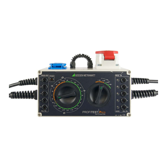
- Page 1 Operating Instructions ⏐ PROFI Adapter for Standards Compliant Testing of PRCDs 3-349-797-15 by Simulating Faults 7/4.19 Important Read carefully before use! Keep on file for future reference! Please observe the manufacturer‘s details on the devices under test!
- Page 2 ⏐ PROFI Operating and Connections Overview Connections Overview To PRCD Inlet (PRCD IN) To PRCD Outlet Mains Connection (PRCD OUT) 1 Coupling plug to the outlet of a 7 Mains power cable with earthing contact plug 3-phase PRCD 8 3-phase mains power cable with 2 Earthing contact plug to the outlet of a CEE outlet (1P+N+PE 16 A-6h) single-phase PRCD...
-
Page 3: Table Of Contents
⏐ PROFI Symbols – Scope of Delivery – Table of Contents Meanings of Symbols on the Instrument Table of Contents Page 300 V CAT II Maximum permissible voltage and Safety Precautions ........4 measuring category between con- nections and ground Applications .......... -
Page 4: Safety Precautions
⏐ PROFI Safety Precautions Safety Precautions • When using a test probe with coil cord (PROFITEST MXTRA): The test adapter has been manufactured Grip the tip of the test probe firmly, for and tested in accordance with the following example during insertion into a jack safety regulations: socket. -
Page 5: Applications
⏐ PROFI Applications The test adapter may not be used: Testing of PRCDs with the Test Adapter by Simu- lating Faults and Measuring Protective Conductor • If external damage is apparent, for exam- and Insulation Resistance, as well as Tripping ple if parts which conduct dangerous Current and Time to Trip, using the PROFITEST touch voltage are freely accessible,... -
Page 6: Initial Start-Up
⏐ PROFI Initial Start-Up Simulation of “Interference Voltage in the Protec- Initial Start-Up tive Conductor” with Probe See the connections overview on page 2 for In the case of type S PRCDs (PRCD-S), the all connection variants. on/off key is made of a conductive material or coated with conductive plastic so that the Testing the LEDs sensor inside the device is capable of... -
Page 7: Connecting The Prcd
⏐ PROFI Measurement with the PROFITEST MXTRA Connecting the PRCD Measuring Protective Conductor Resistance (Rlo) The respective PRCD must be connected to the test adapter for all tests. As opposed to the usual default setting for low-resistance measurements, the device Connecting a Single-Phase PRCD under test does not have to be discon- ➭... -
Page 8: Measuring Insulation Resistance (Riso)
⏐ PROFI Measurement with the PROFITEST MXTRA ➭ Activate the PRCD. ➭ Perform the measurement as described ➭ Perform the measurement as described in section 11 of the operating instruc- tions for the PROFITEST MXTRA. in the operating instructions for the ➭... -
Page 9: Varistor Test (Prcd-K)
⏐ PROFI Measurement with the PROFITEST MXTRA Varistor Test (PRCD-K) Protective Conductor Current Measurement During this measurement, the voltage is ascertained at which the varistor becomes ➭ Connect the PRCD as described in sec- conductive, thus checking the varistor for tion 3.3. -
Page 10: Fault Simulation
⏐ PROFI Fault Simulation Fault Simulation 6.1.2 Simulated Wire Reversal Note! ➭ Turn the left-hand rotary selector If you operate your test adapter at an switch to the L1-PE position in the orange electrical system with a 30 mA area for single-phase wire reversal. breaker, the mains RCCB may be Instead of the L1 LED, the PE LED must light up. -
Page 11: Contacting The "On" Key At The Prcd With The Probe
⏐ PROFI Fault Simulation 6.1.4 Contacting the “ON” Key at the PRCD PRCD-K (single-phase) ➭ Switch mains power on by with the Probe (PRCD-S) turning the right-hand rotary ➭ Turn the left-hand rotary selector switch selector switch to the 1~ ON position. to the first ON position in the orange area for single-phase interruption. -
Page 12: Prcd-S (3-Phase)
⏐ PROFI Fault Simulation PRCD-S (3-phase) 6.3.1 Simulated Interruption ➭ Switch mains power on by ➭ Start with the left-hand rotary se- turning the right-hand rotary lector switch in the first ON position in the selector switch to the 3~ ON position. green area for single-phase interruption. -
Page 13: Simulated Wire Reversal
⏐ PROFI Fault Simulation 6.3.2 Simulated Wire Reversal ➭ Turn the left-hand rotary selector switch to the L1-N position in the green area for 3-phase wire reversal. ➭ Switch through the positions, one after the other, in the clockwise direction (ta- ble from top to bottom). -
Page 14: Characteristic Values
⏐ PROFI Characteristic Values – Maintenance Characteristic Values Electrical Safety Measurement Measurements with METRACLIP 61 as accessory: category 300 V CAT II Protective conductor Pollution degree current measurement Measuring range: Fuse links 5 ea. FF315mA/500V 0 ... 30 mA AC Ambient Conditions Measurements with PROFITEST MXTRA as -5 ... -
Page 15: Safety Checks - Testing In Compliance With
⏐ PROFI Maintenance The fuses may only be replaced when the • Reversed conductors: instrument is voltage-free, i.e. the instrument L1-PE (orange), L1-PE (green), L2-PE (green), L3-PE (green) → > 30 MΩ must be disconnected from mains supply power and may not be connected to a mea- •... -
Page 16: Contact Current Measurement
⏐ PROFI Maintenance – Addresses 8.2.3 Contact Current Measurement www.gossenmetrawatt.com by entering the search term WEEE. The measurement of contact current is per- In accordance with WEEE 2012/ formed on the screw connections of the PRCD IN 19/EU and ElektroG, we identify sockets with standard limit values (I <...
Need help?
Do you have a question about the PROFITEST PRCD and is the answer not in the manual?
Questions and answers