Advertisement
P
L
ARTS
IST
quantity
description
1
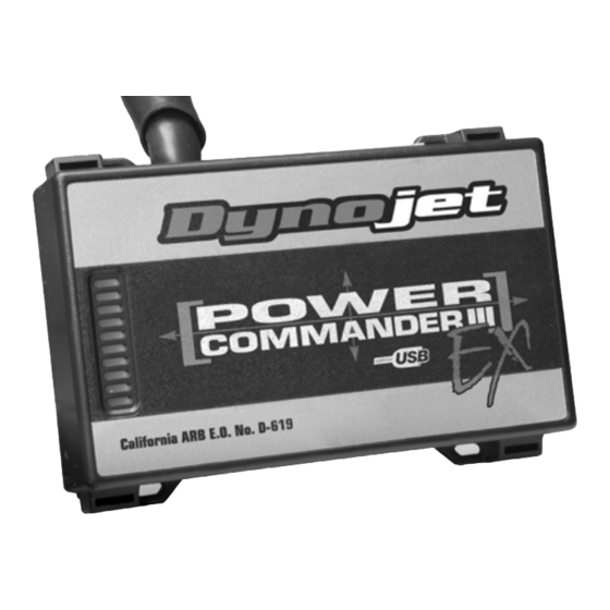
power commander EX
1
USB cable
1
cd-rom
1
installation guide
1
power adapter
2
power commander EX decal
2
dynojet decal
2
velcro strip
2
zip tie
1
alcohol swab
P
LEASE
D
OWNLOAD THE
Dynojet Research • 2191 Mendenhall Drive • North Las Vegas, NV 89081 • (800) 992-4993
i818-511EX
2008 H
I
NSTALLATION
R
A
D
EAD
LL
IRECTIONS
P
C
OWER
OMMANDER SOFTWARE AND LATEST MAPS FROM OUR WEBSITE
.
WWW
POWERCOMMANDER
D
ARLEY
AVIDSON
T
OURING
I
NSTRUCTIONS
expansion port
B
S
EFORE
TARTING
.
COM
I
NSTALLATION
:
2008 Harley Davidson Touring - PCIII USB EX - 1
USB port
Advertisement
Table of Contents

Summary of Contents for Dynojet Power Commander III
- Page 1 TARTING NSTALLATION OWNLOAD THE OWER OMMANDER SOFTWARE AND LATEST MAPS FROM OUR WEBSITE POWERCOMMANDER Dynojet Research • 2191 Mendenhall Drive • North Las Vegas, NV 89081 • (800) 992-4993 2008 Harley Davidson Touring - PCIII USB EX - 1 i818-511EX...
- Page 2 SE THE OLLOWING NSTRUCTIONS FOR unplug this -ABS M ODELS connector The ignition must be turned OFF before installation. Remove the seat. Remove the right hand side cover. Unplug the stock wiring harness from the ECM as shown in Figure A. remove this bolt Remove the bolt securing the ECM tray as shown in Figure A.
- Page 3 10 Reinstall the ECM and tray back into the stock PCIII USB EX position. connector 11 Attach the connector from the PCIII USB EX to the stock ECM as shown in Figure D. 12 Attach the connector from the PCIII USB EX to the stock wiring harness as shown in Figure E.
- Page 4 SE THE OLLOWING NSTRUCTIONS FOR unplug this ODELS connector The ignition must be turned OFF before installation. Remove the seat. Remove the right hand side cover. Unplug the stock wiring harness from the ECM as shown in Figure F. remove this bolt Remove the bolt securing the ECM tray as shown in Figure F.
- Page 5 Another view of the PCIII USB EX and stock PCIII USB EX wiring harness connection positioned in front connector of the battery (shown in Figure H and Figure I). Reinstall the ECM and ECM tray using the bolt removed earlier. zip tie The tray needs to fit between the battery and the PCIII USB EX connector.


Need help?
Do you have a question about the Power Commander III and is the answer not in the manual?
Questions and answers