Table of Contents
Advertisement
Quick Links
Parts List
1
Power Commander
1
USB Cable
1
CD-ROM
1
Installation Guide
1
Power Adapter
2
Power Commander Decals
2
Dynojet Decals
1
Velcro
Strip
®
1
Alcohol Swab
The ignition MUST be turned
OFF before installation!
You can also download the Power
Commander software and latest maps
from our web site at:
www.powercommander.com
PLEASE READ ALL DIRECTIONS BEFORE STARTING INSTALLATION
Dynojet Research 2191 Mendenhall Drive North Las Vegas, NV 89031 (800) 992-4993 www.powercommander.com
i213-411
2004 Kawasaki ZX6RR
Installation Instructions
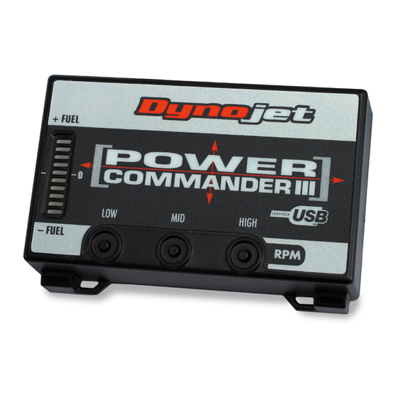
Button Adjustment Display
Faceplate Buttons
Expansion Port
2004 Kawasaki ZX6RR - PCIII USB - 1
USB Port
Advertisement
Table of Contents

Related Manuals for Dynojet power commander III


Summary of Contents for Dynojet power commander III
-
Page 1: Installation Instructions
Commander software and latest maps from our web site at: www.powercommander.com PLEASE READ ALL DIRECTIONS BEFORE STARTING INSTALLATION Dynojet Research 2191 Mendenhall Drive North Las Vegas, NV 89031 (800) 992-4993 www.powercommander.com i213-411 2004 Kawasaki ZX6RR - PCIII USB - 1... - Page 2 Remove the tail section by removing the six push pins on the underside of the tail section. Remove these bolts Remove the two bolts that hold the tail section to the subframe (Fig. A). Tray Pull the tray out of the tail section.
- Page 3 Route connectors from the PCIII one at a time between the frame and inner fender (Fig. D). Route the PCIII harness under the frame crossover Frame Crossover (Fig. E). The battery may need to be removed to allow clearance for the connectors and harness.
- Page 4 Unplug the throttle body connector (Fig. G). This connector is located under- Connector neath the throttle bodies. Plug the connectors that are closest to the PCIII unit in- line of the stock throttle body connector (Fig. H). Stock PCIII 10. Unplug the Throttle Position Sensor connector.
- Page 5 11. Plug the other connectors from the PCIII in-line of the stock TPS connectors (Fig. J). PCIII Stock 12. Connect the ground wire from the PCIII to the negative side of the battery (Fig. K). 13. Make sure all connections are secure and that the wiring harness will not get pinched or chaffed.
Need help?
Do you have a question about the power commander III and is the answer not in the manual?
Questions and answers