
Subscribe to Our Youtube Channel
Related Manuals for Observa Telecom LTE CPE SQI4N4


Summary of Contents for Observa Telecom LTE CPE SQI4N4
- Page 1 LTE CPE SQI4N4 Quick Start Guide FCC ID: 2AI24QCI4NU FCC ID: 2AI24SQO14 Issue 01 Date 2016‐08 ...
-
Page 2: Table Of Contents
Contents 1 About This Document ....................... 2 2 Device Panel .......................... 3 3 What You Need ......................... 3 4 How It Works .......................... 4 5 Set Up the Hardware ......................... 5 5.1 Choose a Location ...................... 5 5.2 Insert a SIM Card to the Slot .................. 6 5.3 Outdoor (SQO14) LED Behavior .................. 7 5.4 Connect the SQO14 to the QCI4NU ................ 8 5.5 ... -
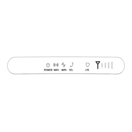
Page 3: Device Panel
includes two o parts, an in door unit and d an outdoor r unit. Please see following g matrixshow ws for detailed info ormation. Indoo or Unit FCC ID: 2A AI24QCI4NU odel: QCI4NU U LTE CPE SQ I4N4 Outd door Unit FCC ID: 2A AI24SQO14 odel: SQO14 Devic e Pane el Figu re 2‐1 QCI4N NU Rear Pane l. Figure 2‐1 Figu re 2‐2 QCI4N NU Front Pane el. Figure 2‐2 What You N Need ... - Page 4 How I It Wor rks Figu re 4‐1 LAN an nd WAN. Figure 4‐1 The SQO14 connects to t the LTE netwo ork. The SQO14 is connected to the QCI4N NU. The QCI4NU U functions as s a LAN & Wi‐ ‐Fi access gat teway. The QCI4NU Ualso serves a as telephone adapter. This Quick Start Guide shows s you how to set up your SQO14 and QCI4NUin or r der to acces s the Inte rnet. ...
-
Page 5: Set Up The Hardware
5 Set Up the Hardware CAUTION Before you begin, ensure that you are familiar with all safety and accident prevention procedures necessary for working at heights and with electricity. Do NOT install the SQO14 during a lightning storm. 5.1 Choose a Location The SQO14 can be mounted on a pole or antenna mast or on a wall using the supplied bracket mount. Choose a mounting point that is sturdy enough to hold the SQO14, even during high winds. When choosing a location to install the SQO14, remember that the SQO14’s front panel should point towards your service provider’s nearest base station. You do not need to be able ... - Page 6 5.2 Ins sert a SIM M Card t to the S lot CAUTION ke sure the S QO14 is turn ned off befor e you insert your SIM car rd. It is recom mmended to NOT conn nect the PoE cable you do this step. Ot therwise, the SIM card ma ay be damage ed. Step p 1 Remove th he cover from m the SQO14. . Figu re 5‐1 Remov ve the cover. Figure 5‐2 Step p 2 Insert you ur SIM card. Figu re 5‐2 Insert SIM Card. Figure 5‐1 Step p 3 Align and ...
-
Page 7: Outdoor (Sqo14) Led Behavior
5.3 Outdoor (SQO14) LED Behavior When set up the Outdoor Unit, the LED will have the following behavior. CPE State Description LED Behavior LED illustration Power On Power supply normal Power LED on Detect with no After CPE power on, Power LET and three signal SIM card detecting no SIM card strength LEDs blinking together, the frequency is 2 times per second. - Page 8 5.4 Con nnect th he SQO1 14 to the e QCI4NU U Lay a CAT5e Ethe ernet cable (n not included ) from your i intended QCI I4NU location n to our inte nded O14 location. The maximum di stance of the e CAT5e cable e is limited to 100 meters. Sign al attenuatio on may result if you use ca ble extender rs to cover a g greater distan nce. If yo ou intend to use cable tie es or other m methods ...
-
Page 9: Mount The Sqo14
Step 1 Connect the CAT5e Ethernet cable which is already connected to the SQO14 to the QCI4NU’s RJ‐45 PoE port. CAUTION Do not connect a computer or a switch directly to the QCI4NU’s PoE port due to the high PoE power. Step ... - Page 10 Metal hose clamps Figure 5‐3 pole typemounting A Using a screwdriver to lock the metal hose clamps, fixed terminal equipment.(Using software to enable terminal equipment aligned in the direction of the base station, achieve the best effect.) Using a screwdriver to lock the metal hose clamps ...
-
Page 11: Connect To The Internet
If the diameter of pole between 25mm and 30mm, it’s needed to use the rubber C-type ring to add the diameter of the pole. Figure 5‐5 C-type ring 6 Connect to the Internet Step 1 Open a web browser and enter the URL http://192.168.100.1 of indoor unit Step 2 Enter the default Username and Password. Click Login. (Fields are case‐sensitive.) Figure 6‐1 Login Screen. Figure 6‐1 NOTE If the login screen does not open, make sure internet browser’s proxy settings disabled. Your computer should also be set to get an IP address automatically from the LTE Router DHCP Server, ... - Page 12 Figu re 6‐2 Main S Screen Figure 6‐2 If th e LTE Signal Bar & Intern et Icons loca ated above of f the page ar re grayed out t , it means th hat it cann not acquire LT TE Signal. To c check signal, go to Netwo ork Menu ...
-
Page 13: Wireless
Figure 6‐3 Network Figure 6‐3 If the SINR is below 10db, replanning or repositioning of the outdoor (SQO14) antenna is required. Note: SINR threshold parameters is ≥10 db 7 Wireless 7.1 Turn the Wireless On or off Step 1The WIFI is set to default as ON. Step 2You can also press the WIRELESS On/Off button for one second and release it. ... -
Page 14: Power Led
Troub bleshoo oting Use this section i f you have pr roblems with h your LTE Dev vice. 8.1 Pow wer LED D Figu re 9‐1 Power r LED Symbol Figure 8‐1 Tabl e 9‐1 Power LED Definitio on LED COLO OR STAT US DESC CRIPTION R Blue No Po ower Supply Stead dy On Powe er on If th e power LED is off, please e check. ... -
Page 15: Lte Led
8.3 LTE LED Figure 9‐3 LTE LED Symbol Figure 8‐3 Table 9‐2 LTE LED Definition LED COLOR STATUS DESCRIPTION LTE Blue Steady On In LTE network Blinking LTE scan, connect, complete LTE connectivity OFF No access in LTE network If the LTE LED is off or blinking continuously, please check: Step 1PoE cable MUST be connected between QCI4NU and SQO14 device. Step 2 Re‐power on the QCI4NU device. Step 3Wait until the LED indicator steadies. Step 4 If the problem still persists, device hardware component may be defective, please contact our technical support. 8.4 WiFi LED Figure 9‐4 WIFI LED Symbol Figure 8‐4 Table 9‐3 WLAN LED Definition LED COLOR STATUS DESCRIPTION WIFI Blue OFF WLAN function disable Blinking ... -
Page 16: Ethernet 1-4 Leds
8.5 ETHERNET 14 LEDs Figure 9‐6 ETHERNET 1~3 LEDs Symbol Figure 8‐5 Table 9‐5 ETHERNET 1‐3 LEDs Definition LED COLOR STATUS DESCRIPTION LAN1~LAN3 Green Steady On Ethernet connection is normal Blinking Ethernet interface data being transmitted OFF Ethernet connection is not established WAN/POE Green Steady On WAN connection is normal Blinking WAN interface data being transmitted OFF ... -
Page 17: Online Help
Indoor LTE CPE Online Help ... - Page 18 Index 1 Getting Started .......................... 5 1.1 Welcome to the CPE .................... 5 1.2 Computer Configuration Requirements .............. 5 1.3 Logging In to the Web Management Page .............. 5 2 Overview ........................... 6 2.1 Viewing the System Information ................ 6 2.2 Viewing the Version Information ................ 7 2.3 Viewing CPU Usage .................... 7 2.4 Viewing Memory Usage .................... 8 2.5 Viewing LAN Status .................... ...
- Page 19 5.1.2 Disabling MAC Filter .................. 2 6 5.1.3 Setting Allow access network within the rules .......... 2 6 5.1.4 Setting Deny access network within the rules .......... 2 6 5.1.5 Adding MAC Filtering rule ................ 2 7 5.1.6 Modifying MAC Filtering rule ................ 2 7 5.1.7 Deleting MAC Filtering rule ................ 2 8 5.2 IP Filtering ....................... 2 8 Enabling IP Filtering .................. 2 8 5.2.1 5.2.2 ...
- Page 20 8.7.1 Ping ........................ 4 6 8.7.2 Traceroute ....................... 4 7 8.8 Syslog ........................ 4 8 8.8.1 Local ........................ 4 8 8.8.2 Network ...................... 4 9 8.9 Account ........................ 5 0 8.10 Remote WEB Access .................... 5 1 8.11 Logout ........................ 5 2 9 ...
- Page 21 1 Getting Started 1.1 Welcome to the CPE In this document, the LTE (Long Term Evolution) CPE (customer premises equipment) will be replaced by the CPE. Carefully read the following safety symbols to help you use your CPE safely and correctly: Additional information Optional methods or shortcuts for an action Potential problems or conventions that need to be specified 1.2 Computer Configuration Requirements For optimum performance, make sure your computer meets the following requirements. Item Requirement Pentium 500 MHz or higher Memory 128 MB RAM or higher ...
- Page 22 Launch Internet Explorer, enter http://192.168.1.1 in the address bar, and press Enter. As shown in Figure 1‐1. Figure 1‐1 Enter the user name and password, and click Log In. You can log in to the web management page after the password is verified. As shown in Figure 1‐2. Figure 1‐2 The default user name and password are both admin. To protect your CPE from unauthorized access, change the password after your first login. The CPE supports diagnostic function. If you encounter problems, please contact customer service for the specific using method. To ensure your data safety, it is recommended that you turn on the firewall, and conserve your login and FTP password carefully. 2 Overview 2.1 Viewing the System Information ...
- Page 23 Figure 2‐1 2.2 Viewing the Version Information To view the Version Information, perform the following steps: Choose Overview; In the Version Information area, view the version information, such as Product name, Software version, Firmware version, UBoot version. As shown in Figure 2‐2. Figure 2‐2 2.3 Viewing CPU Usage To view the CPU usage, perform the following steps: Choose Overview; In the CPU Usage area, view the CPU usage information, such as Current CPU usage, Max CPU usage, Min CPU usage. As shown in Figure 2‐3. ...
- Page 24 Figure 2‐3 2.4 Viewing Memory Usage To view the memory usage, perform the following steps: Choose Overview; In the Memory Usage area, view the memory usage information, such as Total memory, Current memory usage, Max memory usage and Min memory usage. As shown in Figure 2‐4. Figure 2‐4 2.5 Viewing LAN Status To view the LAN status, perform the following steps: Choose Overview; In the LAN Status area, view the LAN status, such as Mac address, IP address and Subnet ...
- Page 25 Figure 2‐5 2.6 Viewing Wi‐Fi Status To view the Wi‐Fi status, perform the following steps: 1. Choose Overview; 2. In the Wi‐Fi Status area, view the information about Wi‐Fi status, SSID, Chanel NO., MAC address and WDS status. As shown in Figure 2‐6. Figure 2‐6 2.7 Viewing WAN Status To view the WAN status, perform the following steps: Choose Overview; In the WAN Status area, view the information about WAN, such as Connect Mode, MAC Address, IP Address, Subnet Mask, Gateway, DNS Server, Online time, DL&UL Data Rate. As ...
- Page 26 Figure 2‐7 2.8 Viewing Throughput Statistics To view the throughput statistics, perform the following steps: Choose Overview; In the Throughput Statistics area, view the throughput statistics, such as WAN throughput and LAN throughput. As shown in Figure 2‐8. Figure 2‐8 2.9 Viewing Device List To view the device list, perform the following steps: Choose Overview; In the Device List area, view the device information which connect to the CPE, such as Device name, Mac address, IP address and Lease time. As shown in Figure 2‐9. Figure 2‐9 ...
- Page 27 3 Network Setting 3.1 WAN Setting 3.1.1 Network Mode To set the network mode, perform the following steps: 1. Choose Network Setting>WAN Settings; 2. In the Network Mode area, select a mode between LTE and Ethernet; 3. Click Submit. As shown in Figure 3‐1. Figure 3‐1 3.1.2 MTU Setting To set the WAN MTU size, perform the following steps: Choose Network Setting>WAN Settings; In the Network mode area, you can configure the MTU size; Click Submit. As shown in Figure 3‐2. Figure 3‐2 ...
- Page 28 3.1.3 Setting Connect ODU To set the WAN connect ODU, perform the following steps: Choose Network Setting>WAN Settings; In the Settings area, enable Connect ODU; Click Submit. As shown in Figure 3‐3. Figure 3‐3 3.1.4 WAN Network Parameters Setting Set WAN connect mode as DHCP, perform the following steps: Choose Network Setting>WAN Settings; In the Settings area, Set connect mode as DHCP IP; Click Submit. As shown in Figure 3‐4. Figure 3‐4 Set WAN connect mode as Static IP, perform the following steps: Choose Network Setting>WAN Settings; In the Settings area, Set connect mode as Static IP; Setting IP address, Subnet mask, Gateway and DNS; Click Submit. As shown in Figure 3‐5. ...
- Page 29 Figure 3‐5 3.2 Outdoor 4G Status To view the outdoor 4G status, perform the following steps: 1. Choose Network Setting>Outdoor 4G Status; 2. In the Outdoor 4G Status area, you can also view the network information such as connect mode, IMSI, RSSI, frequency, DL&UL MCS, RSRP, RSRQ, CINR, SINR, TxPower, Cell ID, PCI, MCC and MNC. As shown in Figure 3‐6. ...
- Page 30 Figure 3‐6 3.3 LAN Setting 3.3.1 Setting LAN Host Parameters By default, the IP address is 192.168.1.1 with a subnet mask of 255.255.255.0. You can change the host IP address to another individual IP address that is easy to remember. Make sure that IP address is unique on your network. If you change the IP address of the CPE, you need to access the web management page with the new IP address. To change the IP address of the CPE, perform the following steps: Choose Network Setting>LAN Settings. In the LAN Host Settings area, set IP address and subnet mask. In the DHCP Setting area, set the DHCP server to Enable. Click Submit. As shown in Figure 3‐7. ...
- Page 31 Figure 3‐7 3.3.2 Configuration the DHCP Server DHCP enables individual clients to automatically obtain TCP/IP configuration when the server powers on. You can configure the CPE as a DHCP server or disable it. When configured as a DHCP server, the CPE automatically provides the TCP/IP configuration for the LAN clients that support DHCP client capabilities. If DHCP server services are disabled, you must have another DHCP server on your LAN, or each client must be manually configured. To configure DHCP settings, perform the following steps: Choose Network Setting > LAN Settings. Set the DHCP server to Enable. Set Start IP address. This IP address must be different from the IP address set on the LAN Host Settings area, but they must be on the same network segment. Set End IP address. This IP address must be different from the IP address set on the LAN Host Settings area, but they must be on the same network segment. ...
- Page 32 Figure 3‐8 3.3.3 Bundled Address List You can bind an IP address to a device based on its MAC address. The device will receive the same IP address each time it accesses the DHCP server. For example, you can bind an IP address to an FTP server on the LAN. To add an item to the setup list, perform the following steps: Choose Network Setting > LAN Settings. Click Add list. Set the MAC address and IP Address. Click Submit. As shown in Figure 3‐9. Figure 3‐9 To modify an item in the setup list, perform the following steps: Choose Network Setting > LAN Settings. Choose the item to be modified, and click Edit. Set the MAC address and IP Address. Click Submit. As shown in Figure 3‐10. ...
- Page 33 Figure 3‐10 To delete an item in the setup list, perform the following steps: 1. Choose Network Setting > LAN Settings. 2. Choose the item to be deleted, and click Delete. 3.4 DMZ Settings If the demilitarized zone (DMZ) is enabled, the packets sent from the WAN are directly sent to a specified IP address on the LAN before being discarded by the firewall. To set DMZ, perform the following steps: Choose Network Setting > DMZ Settings. Set DMZ to Enable. (Optional) Set ICMP Redirect to Enable. Set Host address. This IP address must be different from the IP address set on the LAN Host Settings page, but they must be on the same network segment. Click Submit. As shown in Figure 3‐11. Figure 3‐11 ...
- Page 34 3.5 Static Route 3.5.1 Add Static Route To add a static route, perform the following steps: Choose Network Setting>Static Route. Click Add list. Set the Dest IP address and Subnet mask. Select an Interface from the drop‐down list. If you select LAN as the interface, you need set a Gateway. Click Submit. As shown in Figure 3‐12. Figure 3‐12 3.5.2 Modify Static Route To modify an access restriction rule, perform the following steps: Choose Security>Static Route. Choose the item to be modified, and click Edit. Repeat steps 3 through 5 in the previous procedure. Click Submit. As shown in Figure 3‐13. ...
- Page 35 Figure 3‐13 3.5.3 Delete Static Route To delete a static route, perform the following steps: Choose Security>Static Route. Choose the item to be deleted, and click Delete. 4 Wi‐Fi 4.1 WLAN Setting This function enables you to configure the Wi‐Fi parameters. 4.1.1 Setting General Parameters To configure the general Wi‐Fi settings, perform the following steps: Choose Wi‐Fi > Wi‐Fi Settings. In the General Settings area, set WLAN to Enable. Set Mode to one of the values described in the following table: Parameter Value Description 802.11b/g/n The Wi‐Fi client can connect to the CPE in 802.11b, 802.11g, or 802.11n mode. If the client connects to the CPE in 802.11n mode, the Advanced Encryption Standard (AES)
- Page 36 encryption mode is required. 802.11b/g The Wi‐Fi client can connect to the CPE in 802.11b or 802.11g mode. 802.11b The Wi‐Fi client can connect to the CPE in 802.11b mode. 802.11g The Wi‐Fi client can connect to the CPE in 802.11g mode. Set the Channel No. from 1 to 11. Click Submit. As shown in Figure 4‐1. ...
- Page 37 The Wi‐Fi client connects to the CPE using the found SSID. Set Maximum number of devices. This parameter indicates the maximum number of Wi‐Fi clients that connect to the CPE. A maximum of 32 clients can connect to the CPE. Set Hide SSID broadcast to Enable. If the SSID is hidden, the client cannot detect the CPE's Wi‐Fi information. Set AP isolation to Enable. The clients can connect to the CPE but cannot communicate with each other. Set Security. If Security is set to NONE (not recommended), Wi‐Fi clients directly connect to the CPE. This security level is low. If Security is set to WEP, Wi‐Fi clients connect to the CPE in web‐based encryption mode. If Security is set to WPA‐PSK, Wi‐Fi clients connect to the CPE in WPA‐PSK encryption mode. If Security is set to WPA2‐PSK, Wi‐Fi clients connect to the CPE in WPA2‐PSK encryption mode. This mode is recommended because it has a high security level. If Security is set to WPA‐PSK & WPA2‐PSK, Wi‐Fi clients connect to the CPE in WPA‐PSK&WPA2‐PSK encryption mode. ...
- Page 38 TKIP. WPA‐PSK & WPA‐PSK Only 8 to 63 ASCII characters or 8 to 64 hex WPA2‐PSK characters can be entered. WPA encryption This value can be set to TKIP+AES, AES, or TKIP. Click Submit. As shown in Figure 4‐3. Figure 4‐3 4.3 Access Management 4.3.1 Setting the Access Policy This function enables you to set access restriction policies for each SSID to manage access to the CPE. To configure Wi‐Fi MAC control settings, perform the following steps: Choose Wi‐Fi > Access Management. In the WLAN Access List Settings area, set Access Policy. The access policy can be set to Disable, Blacklist or Whitelist. If SSID's MAC Access is set to Disable, access restrictions do not take effect. If SSID's MAC Access is set to Blacklist, only the devices that are not in the blacklist can connect to the CPE. If SSID's MAC Access is set to Whitelist, only the devices in the whitelist can connect to the CPE. ...
- Page 39 Figure 4‐4 4.3.2 Managing the Wi‐Fi Access List This function enables you to set the SSID access policies based on MAC addresses. To add an item to the Wi‐Fi access list, perform the following steps: Choose Wi‐Fi > Access Management. Click Add. Set MAC address. Click Submit. As shown in Figure 4‐5. Figure 4‐5 To modify an item in the Wi‐Fi access list, perform the following steps: Choose Wi‐Fi > Access Management. Click Edit MAC List. Choose the item to be modified, and click Edit. Set MAC address. Set one of the SSID to Enable to make the MAC address take effect for the SSID. Click Submit. As shown in Figure 4‐6. ...
- Page 40 Figure 4‐6 To delete an item from the Wi‐Fi access list, perform the following steps: Choose Wi‐Fi > Access Management. Choose the item to be deleted, and click Delete. As shown in Figure 4‐7. Figure 4‐7 4.4 WDS The CPE supports the wireless distribution system (WDS). All Wi‐Fi devices in a WDS must be configured to use the same radio channel, encryption mode, SSID, and encryption key. You can set the WDS encryption mode to NONE or WPA/WPA2. If you set the WDS encryption mode to NONE, the Wi‐Fi clients can use NONE or WEP encryption mode. If you set the WDS encryption mode to WPA/WPA2‐PSK, the Wi‐Fi clients can use WPA/WPA2‐PSK encryption mode. After WDS is enabled, disable DHCP on CPEs that are not directly connected to the WAN port. ...
- Page 41 Click Submit. As shown in Figure 4‐8. Figure 4‐8 5 Security 5.1 MAC Filtering This page enables you to configure the MAC address filtering rules. 5.1.1 Enabling MAC Filter To enable MAC address filter, perform the following steps: Choose Security>MAC Filtering Set MAC filtering to Enable. Click Submit. As shown in Figure 5‐1. Figure 5‐1 ...
- Page 42 5.1.2 Disabling MAC Filter To disable MAC address filter, perform the following steps: Choose Security>MAC Filtering Set MAC filtering to Disable. Click Submit. As shown in Figure 5‐2. Figure 5‐2 5.1.3 Setting Allow access network within the rules To set allow access network within the rules, perform the following steps: Choose Security>MAC Filtering. Set Allow access network within the rules. Click Submit. As shown in Figure 5‐3. Figure 5‐3 5.1.4 Setting Deny access network within the rules To set deny access network within the rules, perform the following steps: Choose Security>MAC Filtering. Set Deny access network within the rules. Click Submit. As shown in Figure 5‐4. ...
- Page 43 Figure 5‐4 5.1.5 Adding MAC Filtering rule To add a MAC filtering rule, perform the following steps: Choose Security>MAC Filtering. Click Add list. Set MAC address. Click Submit. As shown in Figure 5‐5. Figure 5‐5 5.1.6 Modifying MAC Filtering rule To modify a MAC address rule, perform the following steps: Choose Security>MAC Filtering. Choose the rule to be modified, and click Edit. Set MAC address. Click Submit. As shown in Figure 5‐6. Figure 5‐6 ...
- Page 44 5.1.7 Deleting MAC Filtering rule To delete a MAC address filter rule, perform the following steps: Choose Security>MAC Filtering. Choose the rule to be deleted, and click Delete. As shown in Figure 5‐7. Figure 5‐7 5.2 IP Filtering Data is filtered by IP address. This page enables you to configure the IP address filtering rules. 5.2.1 Enabling IP Filtering To enable IP Filtering, perform the following steps: Choose Security>IP Filtering. Set IP Filtering Enable. Click Submit. As shown in Figure 5‐8. Figure 5‐8 5.2.2 Disabling IP Filtering To disable IP Filtering, perform the following steps: Choose Security>IP Filtering. Set IP Filtering Disable. Click Submit. As shown in Figure 5‐9. ...
- Page 45 Figure 5‐9 5.2.3 Setting Allow access network outside the rules To set allow access network, perform the following steps: Choose Security>IP Filtering. Set Allow access network outside the rules. Click Submit. As shown in Figure 5‐10. Figure 5‐10 5.2.4 Setting Deny access network outside the rules To set allow access network, perform the following steps: Choose Security>IP Filtering. Set Deny access network outside the rules. Click Submit. As shown in Figure 5‐11. Figure 5‐11 ...
- Page 46 5.2.5 Adding IP Filtering rule Add an IP address filtering rule, perform the following steps: Choose Security>IP Filtering. Click Add list. Set Service. Set Protocol. In the Source IP Address Range box, enter the source IP address or IP address segment to be filtered. In the Source port range box, enter the source port or port segment to be filtered. In the Destination IP Address Range box, enter the destination IP address or IP address segment to be filtered. In the Destination port Range box, enter the destination port or port segment to be filtered. ...
- Page 47 Figure 5‐13 5.2.7 Deleting IP Filtering rule To delete an IP address filtering rule, perform the following steps: Choose Security > IP Filtering. Choose the rule to be deleted, and click Delete. As shown in Figure 5‐14. Figure 5‐14 5.3 URL Filtering Data is filtered by uniform resource locator (URL). This page enables you to configure URL filtering rules. 5.3.1 Enabling URL Filtering To enable URL Filtering, perform the following steps: Choose Security>URL Filtering. Set URL Filtering to Enable. As shown in Figure 5‐15. Click Submit.
- Page 48 Figure 5‐15 5.3.2 Disabling URL Filtering To disable URL Filtering, perform the following steps: Choose Security>URL Filtering. Set URL Filtering to Disable. Click Submit. As shown in Figure 5‐16. Figure 5‐16 5.3.3 Adding URL Filtering list To add a URL filtering list, perform the following steps: Choose Security>URL Filtering. Click Add list. Set URL. Click Submit. As shown in Figure 5‐17. Figure 5‐17 5.3.4 Modify URL Filtering list To modify a URL filtering rule, perform the following steps: Choose Security>URL Filtering. Choose the rule to be modified, and click Edit. ...
- Page 49 Set URL address. Click Submit. As shown in Figure 5‐18. Figure 5‐18 5.3.5 Deleting URL Filtering list To delete a URL list, perform the following steps: Choose Security>URL Filtering. Choose the item to be deleted, and click Delete. As shown in Figure 5‐19. Figure 5‐19 5.4 Port Forwarding When network address translation (NAT) is enabled on the CPE, only the IP address on the WAN side is open to the Internet. If a computer on the LAN is enabled to provide services for the Internet (for example, work as an FTP server), port forwarding is required so that all accesses to the external server port from the Internet are redirected to the server on the LAN. 5.4.1 Adding Port Forwarding rule To add a port forwarding rule, perform the following steps: Choose Security > Port Forwarding. Click Add list. Set Service. Set Protocol. Set Remote port range. ...
- Page 50 The port number ranges from 1 to 65535. Set Local host. This IP address must be different from the IP address that is set on the LAN Host Settings page, but they must be on the same network segment. Set Local port. The port number ranges from 1 to 65535. Click Submit. As shown in Figure 5‐20. Figure 5‐20 5.4.2 Modifying Port Forwarding rule To modify a port forwarding rule, perform the following steps: 1. Choose Security > Port Forwarding. 2. Choose the item to be modified, and click Edit. 3. Repeat steps 3 through7 in the previous procedure. 4. Click Submit. As shown in Figure 5‐21. ...
- Page 51 Figure 5‐21 5.4.3 Deleting Port Forwarding rule To delete a port forwarding rule, perform the following steps: 1. Choose Security > Port Forwarding. 2. Choose the item to be deleted, and click Delete. As shown in Figure 5‐22. Figure 5‐22 5.5 UPnP On this page, you can enable or disable the Universal Plug and Play (UPnP) function. To enable UPnP, perform the following steps: 1. Choose Security > UPnP. 2. Set UPnP to Enable. 3. Click Submit. As shown in Figure 5‐23. ...
- Page 52 Figure 5‐23 6 VPN Setting This function enables you to connect the virtual private network (VPN). To connect the VPN, perform the following steps: Choose VPN Setting. In the VPN Setting area, enable VPN. Select a protocol from Protocol drop‐down list. Enter Username and Password. Click Submit. You can view the status in VPN Status area. As shown in Figure 6‐1. Figure 6‐1 7 VOIP The CPE supports voice services based on the Session Initiation Protocol (SIP) and enables voice service interworking between the Internet and Public Switched Telephone Networks (PSTNs). 7.1 View VOIP Information To view VOIP information, perform the following steps: ...
- Page 53 Choose VOIP > VOIP Information; View the VOIP information, such as the SIP account and status of the SIP registration server. As shown in Figure 7‐1. Figure 7‐1 7.2 Configuring SIP Server To set the SIP server parameters, perform the following steps: Choose VOIP > SIP Server; In the User Agent port box, enter the port of the SIP account provided by your service provider. In the SIP server domain name box, enter the domain name of the SIP server. In the Proxy server address box, enter the address of the proxy server provided by your service provider, for example, 192.168.1.10. In the Proxy server port box, enter the port of the proxy server provided by your service provider, for example, 5060. The value ranges from 1 to 65535. In the Registration server address box, enter the address of the registration server provided by your service provider, for example, 192.168.1.11. In the Registration server port box, enter the port of the registration server provided by your service provider, for example, 5060. The value ranges from 1 to 65535. Click Submit. As shown in Figure 7‐2. Figure 7‐2 ...
- Page 54 7.3 Configuring SIP Account Before configuring SIP accounts, make sure that the registration server has been properly configured. To configure SIP account, perform the following steps: Choose VoIP > SIP Account. Set SIP Account Enable. In the User name and Password boxes, enter the user name and password of the SIP account provided by your service provider. In the Phone Number box, enter the SIP Phone number provided by your service provider. ...
- Page 55 Click Restart. As shown in Figure 8‐1. The CPE then restarts. Figure 8‐1 8.1.2 Reset This function enables you to restore the CPE to its default settings. To restore the CPE, perform the following steps: Choose System>Maintenance. Click Reset. As shown in Figure 8‐2. The CPE is then restored to its default settings. Figure 8‐2 8.1.3 Backup Configuration File You can download the existing configuration file to back it up. To do so: Choose System>Maintenance. Click Download on the Maintenance page. In the displayed dialog box, select the save path and name of the configuration file to be backed up. Click Save. As shown in Figure 8‐3. The procedure for file downloading may vary with the browser you are using. Figure 8‐3 ...
- Page 56 8.1.4 Upload Configuration File You can upload a backed up configuration file to restore the CPE. To do so: Choose System>Maintenance. Click Browse on the Maintenance page. In the displayed dialog box, select the backed up configuration file. Click Open. The dialog box choses. In the box to be right of Configuration file, the save path and name of the backed up configuration file are displayed. Click Upload. As shown in Figure 8‐4. The CPE uploads the backed up configuration file. The CPE then automatically restarts. Figure 8‐4 8.2 Version Manager This function enables you to upgrade the software version of the CPE to the latest version. It is recommended that you upgrade the software because the new version, certain bugs have been fixed and the system stability is usually improved. 8.2.1 Viewing Version Info To view the version info, perform the following steps: Choose System>Version Manager. In the Version Info area, you can view the product name and software version. As shown in Figure 8‐5. Figure 8‐5 ...
- Page 57 8.2.2 Version Upgrade To perform an upgrade successfully, connect the CPE to your computer through a network cable, save the upgrade file on the computer, and make sure the CPE is not connected to anything other than a power adapter and the computer. To perform an upgrade, perform the following steps: Choose System>Version Manager. In the Version Upgrade area, click Browse. In the displayed dialog box, select the target software version file. Click Open. The dialog box choses. The save path and name of the target software version file are displayed in the Update file field. Click Submit. The software upgrade starts. After the upgrade, the CPE automatically restarts and runs the new software version. As shown in Figure 8‐6. During an upgrade, do not power off the CPE or disconnect it from the computer. Figure 8‐6 8.3 FTP auto upgrade To perform a ftp auto upgrade successfully, make sure the CPE is connected to the Internet. To perform a ftp auto upgrade, perform the following steps: Choose System>FTP auto upgrade. Enable FTP auto upgrade. If you want to check new firmware after connect to Internet, you need to enable the item of Check new firmware after connect to Internet. ...
- Page 58 Set Random time. 10. Click Submit. As shown in Figure 8‐7. The CPE will automatically upgrade according to the setting. During an upgrade, do not disconnect the power supply or operate the CPE. Figure 8‐7 8.4 TR069 TR‐069 is a standard for communication between CPEs and the auto‐configuration server (ACS). If your service provider uses the TR069 automatic service provision function, the ACS automatically provides the CPE parameters. If you set the ACS parameters on both the CPE and ACS, the network parameters on the CPE are automatically set using the TR‐069 function, and you do not need to set other parameters on the CPE. To configure the CPE to implement the TR‐069 function, perform the following steps: Choose System>TR‐069 Settings. Set acs URL source. There are two methods, such as URL and DHCP. ...
- Page 59 Figure 8‐8 8.5 Date & Time You can set the system time manually or synchronize it with the network. If you select Sync from network, the CPE regularly synchronizes the time with the specified Network Time Protocol (NTP) server. If you enable daylight saving time (DST), the CPE also adjusts the system time for DST. To set the date and time, perform the following steps: 1. Choose System > Date & Time. 2. Select Set manually. 3. Set Local time or click Sync to automatically fill in the current local system time. 4. Click Submit. As shown in Figure 8‐9. ...
- Page 60 Figure 8‐9 To synchronize the time with the network, perform the following steps: 1. Choose System > Date & Time. 2. Select Sync from network. 3. From the Primary NTP server drop‐down list, select a server as the primary server for time synchronization. 4. From the Secondary NTP server drop‐down list, select a server as the IP address of the secondary server for time synchronization. 5. If you don’t want to use other NTP server, you need to enable Optional ntp server, and set a server IP address. ...
- Page 61 Set DST enable. Set Start Time and End Time. Click Submit. As shown in Figure 8‐11. Figure 8‐11 The CPE will automatically provide the DST time based on the time zone. 8.6 DDNS Dynamic Domain Name Server (DDNS) service is used to map the user's dynamic IP address to a fixed DNS service. To configure DDNS settings, perform the following steps: 1. Choose System > DDNS. 2. Set DDNS to Enable. 3. In Service provider, choose DynDNS.org or oray.com. 4. Enter Domain name and Host name. For example, if the domain name provided by your service provider is test.customtest.dyndns.org, enter customtest.dyndns.org as Domain name, and test as Host name. ...
- Page 62 Figure 8‐12 8.7 Diagnosis If the CPE is not functioning correctly, you can use the diagnosis tools on the Diagnosis page to preliminarily identify the problem so that actions can be taken to solve it. 8.7.1 Ping If the CPE fails to access the Internet, run the ping command to preliminarily identify the problem. To do so: Choose System>Diagnosis. In the Method area, select Ping. Enter the domain name in the Target IP or domain field, for example, www.google.com. Set Packet size and Timeout. Set Count. Click Ping. As shown in Figure 8‐13. Wait until the ping command is executed. The execution results are displayed in the Results box. ...
- Page 63 Figure 8‐13 8.7.2 Traceroute If the CPE fails to access the Internet, run the Traceroute command to preliminarily identify the problem. To do so: Choose System>Diagnosis. In the Method area, select Traceroute. Enter the domain name in the Target IP or domain field. For example, www.google.com. Set Maximum hops ad Timeout. Click Traceroute. As shown in Figure 8‐14. Wait until the traceroue command is executed. The execution results are displayed in the Results box. ...
- Page 64 Figure 8‐14 8.8 Syslog The syslog record user operations and key running events. 8.8.1 Local To set the syslog to local, perform the following steps: Choose System>Syslog. In the Setting area, set the method to Local. In the Level drop‐down list, select a log level. Click Submit. As shown in Figure 8‐15. ...
- Page 65 Figure 8‐15 Viewing local syslog To view the local syslog, perform the following steps: In the Keyword box, set a keyword. Click Pull, the result box will display. 8.8.2 Network To set the syslog to network, perform the following steps: Choose System>Syslog. In the Setting area, set the method to Network. In the Level drop‐down list, select a log level. In the Forward IP address box, set a IP address. Click Submit. As shown in Figure 8‐16. The syslog will transmit to some client to display through network. ...
- Page 66 Figure 8‐16 8.9 Account This function enables you to change the login password of the user. After the password changes, enter the new password the next time you login. To change the password, perform the following steps: Choose System>Account. Select the user name, if you want to change the password of normal user, you need to set Enable User enable. Enter the current password, set a new password ,and confirm the new password. New password and Confirm password must contain 5 to 15 characters. Click Submit. As shown in Figure 8‐17. ...
- Page 67 Figure 8‐17 8.10 Remote WEB Access To configure the parameters of WEB, perform the following steps: Choose System> Remote WEB Access. Set HTTP enable. If you set HTTP disable, you will can’t login the web management page with the HTTP protocol from WAN side. Set HTTP port. If you want to change the login port, you can set a new port in the box, the default HTTP port is 80. Set HTTPS enable. If you want to login the web management page with the HTTPS protocol from WAN side, you need to enable the HTTPS. If you want to login the web management page form the WAN, you need to Enable Allowing login from WAN. Set the HTTPS port. Click Submit. As shown in Figure 8‐18. ...
- Page 68 Figure 8‐18 8.11 Logout To logout the web management page, perform the following steps: Choose System and click Logout It will back to the login page. 9 FAQs The POWER indicator does not turn on. Make sure that the power cable is connected properly and the CPE is powered on. Make sure that the power adapter is compatible with the CPE. Fails to Log in to the web management page. Make sure that the CPE is started. Verify that the CPE is correctly connected to the computer through a network cable. If the problem persists, contact authorized local service suppliers. The CPE fails to search for the wireless network. Check that the power adapter is connected properly. Check that the CPE is placed in an open area that is far away from obstructions, such as concrete or wooden ...
- Page 69 to the default settings. After configuring the parameters, download the configuration file to quickly restore the CPE to the desired settings. ...
-
Page 70: Fcc Regulations
FCC Regulations This device complies with part 15 of the FCC Rules. Operation is subject to the following two conditions: (1) This device may not cause harmful interference, and (2) this device must accept any interference received, including interference that may cause undesired operation. This equipment has been tested and found to comply with the limits for a Class B digital device, pursuant to part 15 of the FCC Rules. These limits are designed to provide reasonable protection against harmful interference in a residential installation. This equipment generates, uses and can radiate radio frequency energy and, if not installed and used in accordance with the instructions, may cause harmful interference to radio communications. However, there is no guarantee that interference will not occur in a particular installation. If this equipment does cause harmful interference to radio or television reception, which can be determined by turning the equipment off and on, the user is encouraged to try to correct the interference by one or more of the following measures: —Reorient or relocate the receiving antenna. —Increase the separation between the equipment and receiver. —Connect the equipment into an outlet on a circuit different from that to which the receiver is connected. —Consult the dealer or an experienced radio/ TV technician for help. Caution : Changes or modifications not expressly approved by the manufacturer could void the user’s authority to operate the equipment. ... - Page 71 This equipment complies with the FCC RF radiation exposure limits set forth for an uncontrolled environment. This equipment should be installed and operated with a minimum distance of 20cm between the radiator and any part of your body. The antennas must not be co‐located with other transmitter antennas. ...
Need help?
Do you have a question about the LTE CPE SQI4N4 and is the answer not in the manual?
Questions and answers