Table of Contents
Advertisement
Quick Links
Advertisement
Table of Contents

Related Manuals for Ruijie RG-AP630 Directional


Summary of Contents for Ruijie RG-AP630 Directional
- Page 1 RG-AP630 Series Access Point Hardware Installation and Reference Guide V1.2...
- Page 2 Ruijie Networks reserves all copyrights of this document. Any reproduction, excerption, backup, modification, transmission, translation or commercial use of this document or any portion of this document, in any form or by any means, without the prior written consent of Ruijie Networks is prohibited. are registered trademarks of Ruijie Networks.
-
Page 3: Obtaining Technical Assistance
It is intended for the users who have some experience in installing and maintaining network hardware. At the same time, it is assumed that the users are already familiar with the related terms and concepts. Obtaining Technical Assistance Ruijie Networks website: http://www.ruijienetworks.com Ruijie service portal: http://case.ruijienetworks.com Related Documents... -
Page 4: Chapter 1 Product Overview
(ACs) to implement wireless data forwarding, security, and access control. The IP67 design adapts Ruijie to inclement outdoor environment, for instance, chillness in northern China and humidity in southern China. This extremely simplifies installation and maintenance. And the built-in directional and omni-directional Ruijie patent X-sense smart antennas offer flexible antenna switch and full coverage for various outdoor circumstances. -
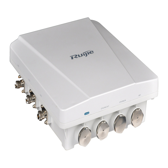
Page 5: Product Appearance
Operating: -40 to 60℃ (-40 to 140℉) Temperature Storage: -40 to 85℃ (-40 to 185℉) Operating: 0% to 100% (non-condensing) Humidity Storage: 0% to 100% (non-condensing) IP Rating IP67 Weight <2.5kg Safety Standards GB4943, EN60601-1-2 (medical care), UL/CSA 60950-1, EN/IEC 60950-1, EN/IEC 60950-22 EMC Standards GB9254-2008, EN301 489, EN55022, FCC Part15, RSS-210 Table 1-2 LEDs of RG-AP630... -
Page 6: Front View
Front View Figure 1-2 Front View of RG-AP630 1. 2.4GHz antenna connector 2. Console port 3.10/100/1000 Base-T auto-sensing Ethernet/PoE 4.10/100/1000 Base-T auto-sensing Note: OUT port Ethernet/PoE IN port 5. SFP combo port 6. 5GHz antenna connector Power Supply The AP supports 802.3af/at compatible PoE. -
Page 7: Chapter 2 Preparing For Installation
Chapter 2 Preparing for Installation To prevent device damage and bodily injury, please read carefully th e safety recommendations described in this chapter. The recommendations do not cover all possible hazardous situations. Grounding and Lightning Protection Use galvanized steel flat bar (or copper) as horizontal grounding conductor. The steel size should be less than 40 mm x 40 mm. -
Page 8: Outdoor Installation
Keep the AP at least 500 meters away from the seaside and do not face it toward the wind from the sea. The installation site should be free from water flooding, seepage, dripping, or condensation. The installation site should be sele cted according to network planning and features of communications equipment, and considerations such as climate, hydrology, geology, earthquake, elec tric power, and transportation. -
Page 9: Fiber Connection
All interference sources, either from outside or inside of the device or application system, affect the device by capacitive coupling, inductive coupling, or electromagnetic waves. Electromagnetic interference (EMI) occurs due to electromagnetic radiation or conduction, depending on the transmission path. Radiation interference occurs when energy, usually radio frequency energy, is emitted from a device and propagated through space that disturbs other victims. -
Page 10: Chapter 3 Installing The Access Point
Chapter 3 Installing the Access Point Before installing the AP, make su re you have carefully read the requirements described in Chapter 2. Installation Flowchart Start Check Choose the Site Install the Bracket on a Pole Install the Bracket on a Wall Install the AP Install External Antenna(Optional) Adjust Antenna Orientation... -
Page 11: Before You Begin
Before You Begin Before you install the AP, verify that all the parts in the packing list are packed and make sure that: The installation site meets temperature and humidity requirements. The installation site is equipped with proper power supply. ... - Page 12 Attach the tie rod to the mounting plate and fasten the rod with the supplied M8 x 40 screws. See Figure 3-2 Figure 3-2 Fixing the Tie Rod on the Mounting Plate...
- Page 13 Wall mount 3) Use the supplied cross-shaped bracket and M8 x 60 screws to implement the wall mount. Attach the cross-shaped bracket to the wall and mark the screw hole locations. See figure 3-3. Figure 3-3 Installing the M8 bolts b.
- Page 14 a. Attach the cross-shaped bracket to a vertical pole with a hose clamp and fasten the clamp with screws by using the Phillips screwdriver. Figure 3-2 Fixing the Bracket on a Vertical Pole b. Hang the AP with the AP-side mounting bracket module to the cross-shaped bracket and tighten the M8×40 screws to secure the AP.
-
Page 15: Adjusting Antenna Orientation
Figure 3-7 Fixing the Bracket on a Horizontal Pole Figure 3-4 Installing the AP on the Horizontal Pole The procedure of horizontal pole mount is similar as that of vertical mount. Adjusting Antenna Orientation Both directional and omni-directional anten nas are available for RG-AP630. The integrated antenna is in parallel with the upper shell. - Page 16 Figure 3-6 Clockwise Horizontal Rotation (+60°) (-60°to +60°horizontal rotation available) Figure 3-7 Vertical Rotation (0°)
- Page 17 Figure 3-8 Clockwise Vertical Rotation (+60°) (0°to 90° vertical rotation available) Omni-directional Antenna Orientation Figure 3-9 Anticlockwise Vertical Rotation (-90°)
-
Page 18: Installing Security Lock (Optional)
Installing Security Lock (Optional) The security lock is customer-supplied. The lock loop on the AP is for your security needs. You can fasten the AP to a fixture as follows: Fasten the cable of a securit y lock to a fixture; Secure the lock plate into th e lock loop. -
Page 19: Connecting The Network Cable
Connecting the network cable Waterproof material is customer-supplied. Trim the network cable according to the distance between the AP and the power supply. Thread the cable through liquid-tight ad apter and add a plug to the end. See figure 3-16. Figure 3-12 Threading the Network Cable Wrap the cable between B and C up with two or three la yers of liquid-tight material. -
Page 20: Installing Outdoor Antennas (Optional)
Outdoor antennas fall into directional and omni-directional antennas. The integrated RG-AP630 antenna meets the demands in most cases. To obtain external antennas for special occasions, go to http://www.ruijie.com.cn/. Installing Outdoor Directional Antennas To protect your outdoor directional antennas from lightning strikes, install a lightning rod on top of the pole. - Page 21 Ensure the height of the antenna can provide desired signal coverage. Ensure the top of the antenna is within the 45° protection ang Figure 3-19 Mounting the Outdoor Omni-directional Antennas...
-
Page 22: Appendix A Connectors And Media
Appendix A Connectors and Media 1000BASE-T/100BASE-TX/10BASE-T The 1000BASE-T/100BASE-TX/10BASE-T is a 10/100/1000 Mbps auto-negotiation port that supports auto MDI/MDIX. Compliant with IEEE 802.3ab, 1000BASE-T requires Category 5e 100-ohm UTP or STP (STP is recommended) with a maximum distance of 100 meters (328 feet). 1000BASE-T requires all four pairs of wires be connected for data transmission, as shown in Figure A-1. - Page 23 Fiber Connection You can choose to use single mode or multi-mode fibers according to the transceiver module types. Figure A-3 shows connection of fiber cables. Figure A-3 Fiber Connection...
-
Page 24: Appendix B Mini-Gbic Module Specifications
Appendix B Mini-GBIC Module Specifications Ruijie provides various Gigabit SFP transceivers (Mini-GBIC modules) for interfaces of wireless access controllers. You can select the most suitable SFP modules as needed. This appendix describes the models and specifications of some of the Gigabit SFP transceivers for your reference. -
Page 25: Appendix C 10-Year Hazardous Material Contents
SJ/T 11363-2006 standard. Note: This table lists the substances that may be included in Ruijie products. The preceding substances may not be included in different models. Please check the contents of the actual model.
Need help?
Do you have a question about the RG-AP630 Directional and is the answer not in the manual?
Questions and answers