
Related Manuals for Ruijie RG-AP680 CD Series


Summary of Contents for Ruijie RG-AP680 CD Series
- Page 1 Ruijie RG-AP680(CD) Series Access Points Hardware Installation and Reference Guide V1.0...
- Page 2 This document is provided “as is”. The contents of this document are subject to change without any notice. Please obtain the latest information through the Ruijie Networks website. Ruijie Networks endeavors to ensure content accuracy and will not shoulder any responsibility for losses and damages caused due to content omissions, inaccuracies or errors.
- Page 3 It is intended for the users who have some experience in installing and maintaining network hardware. At the same time, it is assumed that the users are already familiar with the related terms and concepts. Obtaining Technical Assistance Ruijie Networks Website: https://www.ruijienetworks.com/ Technical Support Website: https://ruijienetworks.com/support...
-
Page 4: Product Overview
· 1 Product Overview The RG-AP680(CD), adhering to the latest 802.11ax standard, is a wireless access point (AP) designed by Ruijie for campus scenarios. Featuring two spatial streams each radio, this dual-radio and dual- band AP provides an access rate up to 575 Mbps at 2.4G and 1,200 Mbps at 5G, totaling 1.775 Gbps. -
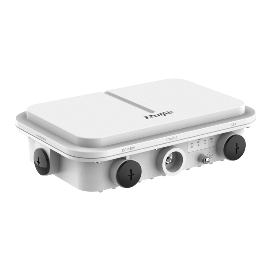
Page 5: Product Appearance
Hardware Installation and Reference Guide Product Overview · 11ax HE80: -76dBm (MCS0), -49dBm (MCS11) · Maximum Transmit 28 dBm (Country-specific) Power Dimensions 251 mm × 168 mm × 64 mm (Excluding the bracket) Weight < 1.5kg One 10/100/1000 Base-T uplink Ethernet port One SFP port Ports One port for 48 V DC power supply... -
Page 6: Power Supply
Hardware Installation and Reference Guide Product Overview · · 1. Condole port and reset button 3. 10/100/1000 Base-T auto-sensing Ethernet/PoE port Note: 2. Port for 48 V DC power supply 4. SFP port 1.3 Power Supply The AP supports 802.3af PoE or 44 - 57 V DC power supply. When PoE power supply is adopted, please make sure the peer end support 802.3af/802.3at, too. -
Page 7: Preparing For Installation
Hardware Installation and Reference Guide Preparing for Installation · · 2 Preparing for Installation To prevent device damage and physical injury, please read carefully the safety recommendations described in this chapter. Recommendations do not cover all possible hazardous situations. 2.1 Grounding and Lightning Protection ... -
Page 8: Temperature And Humidity
Hardware Installation and Reference Guide Preparing for Installation · 2.2.1 Temperature and Humidity · Table 2-1 Required Temperature and Humidity for the RG-AP680(CD) Series -40° C to 65° C (-40° F to 149° F) Operating Temperature Operating Humidity 0% to 100% (non-condensing) 2.2.2 Outdoor Installation The AP can be mounted on a wall or pole. -
Page 9: Fiber Connection
Hardware Installation and Reference Guide Preparing for Installation · · 2.3 Fiber Connection Before connecting fiber cables, make sure the model of the optical transceiver and fiber type match the optical port. The transmit port on the local device should be connected to the receive port on the peer device and vice versa. 2.4 Installation Tools Table 2-2 Installation Tools Marker, Phillips (crosshead) screwdriver, slotted screwdriver, drill, paper knife, crimping pliers,... -
Page 10: Installing The Access Point
Hardware Installation and Reference Guide Installing the Access Point · · 3 Installing the Access Point Before installing the AP, make sure you have carefully read the requirements described in Chapter 2. 3.1 Installation Flowchart 3.2 Before You Begin Before you install the AP, verify that all the parts in the package contents are there and make sure that: ... -
Page 11: Installing The Ap
Hardware Installation and Reference Guide Installing the Access Point · · 3.3 Precautions RG-AP680(CD) can be mounted on a wall and a pole (diameter: 50mm to 140mm, thickness: ≥2.5mm). Otherwise, the AP could fall down and cause injuries. The installation site can vary due to on-the-spot surveys conducted by technical personnel. - Page 12 Hardware Installation and Reference Guide Installing the Access Point · · Wall mount Use four M8 x 60 screws to implement the wall mount. (The screws, made of SUS304 stainless steel, are customer-supplied.) Attach the bracket to the wall and mark the screw hole locations. Align the screw holes on the bracket and those on the wall, and tighten the M8×40 screws to mount the bracket.
- Page 13 Hardware Installation and Reference Guide Installing the Access Point · · 3.5 Connecting Cables Connecting the grounding cable The grounding cable is made on site. Connect the supplied grounding wire (yellow-green) to the AP grounding hole on one end and ground the wire on the other end through OT terminals. To avoid waste, adjust the cable length for actual demands.
- Page 14 Hardware Installation and Reference Guide Installing the Access Point · · Wrap the cable between B and C upwards with two or three layers of liquid-tight material. See figure 3-7. Figure 3-7 Wrapping Liquid-tight Material around Cable Insert the plug into the 10G ETH/PoE port and tighten B, C and D in order. Make sure the plug is correctly inserted.
- Page 15 Hardware Installation and Reference Guide Installing the Access Point · Connecting the DC Power Cord (Optional) · Waterproofing material is customer-supplied. When you choose DC power supply to power the AP, please make sure the port for DC power supply face to the ground.
-
Page 16: Appendix A Connectors And Media
Hardware Installation and Reference Guide Appendix A Connectors and Media · · Appendix A Connectors and Media 1000BASE-T/100BASE-TX/10BASE-T The 1000BASE-T/100BASE-TX/10BASE-T is a 10/100/1000 Mbps auto-negotiation port that supports auto MDI/MDIX. Compliant with IEEE 802.3ab, 1000BASE-T requires Category 5e 100-ohm UTP or STP (STP is recommended) with a maximum distance of 100 meters (328 feet). - Page 17 Hardware Installation and Reference Guide Appendix A Connectors and Media · Fiber Connection · You can choose to use single mode or multimode fibers according to the transceiver module types. Figure A-4 shows connection of fiber cables. Figure A-4 Fiber Connection...
-
Page 18: Appendix B Mini-Gbic Module Specifications
· Appendix B Mini-GBIC Module Specifications Ruijie provides various Gigabit SFP transceivers (Mini-GBIC modules) for interfaces of wireless access controllers. You can select the most suitable SFP modules as needed. This appendix describes the models and specifications of some of the Gigabit SFP transceivers for your reference. -
Page 19: Appendix C Cabling Recommendations
Hardware Installation and Reference Guide Appendix C Cabling Recommendations · · Appendix C Cabling Recommendations During installation, route cable bundles upward or downward along the sides of the rack depending on the actual situation in the equipment room. All cable connectors should be placed at the bottom of the cabinet rather than be exposed outside of the cabinet. - Page 20 Hardware Installation and Reference Guide Appendix C Cabling Recommendations · · Route and bundle power, signal, ground cables separately. When the cables are close to each other, cross them. When power cables run parallel to signal cables, the distance between them must be greater than 30 mm. ...
- Page 21 Hardware Installation and Reference Guide Appendix C Cabling Recommendations · · Wrap up unnecessary or excess cables and bind them to the appropriate rack position, where device operation is not affected and no damages occur to the device and cables during debugging. ...
- Page 22 Hardware Installation and Reference Guide Appendix C Cabling Recommendations · Diameter of Cable Bundle (mm) Space between Bundles (mm) · 80 to 150 10 to 30 150 to 200 200 to 300 Do not tie knots for cables or cable bundles. ...
Need help?
Do you have a question about the RG-AP680 CD Series and is the answer not in the manual?
Questions and answers