
Subscribe to Our Youtube Channel
Related Manuals for Ruijie RG-AP680-L


Summary of Contents for Ruijie RG-AP680-L
- Page 1 Ruijie RG-AP680-L Access Point Hardware Installation and Reference Guide Document Version: V1.0 Date: December 23, 2022 Copyright © 2022 Ruijie Networks...
- Page 2 Due to product version upgrades or other reasons, the content of this document will be updated from time to time. Ruijie Networks reserves the right to modify the content of the document without any notice or prompt. This manual is for reference only. Ruijie Networks endeavors to ensure content accuracy and will not shoulder...
-
Page 3: Preface
Preface Intended Audience This document is intended for: Network engineers Technical support and servicing engineers Network administrators Technical Support Ruijie Networks website: https://www.ruijienetworks.com/ Technical support website: https://ruijienetworks.com/support Case portal: https://caseportal.ruijienetworks.com Community: https://community.ruijienetworks.com ... -
Page 4: Table Of Contents
Contents Preface ..............................I 1 Product Overview ..........................1 1.1 About the RG-AP680-L Access Point ..................1 1.2 Hardware Features ........................1 1.3 Package Contents........................3 1.4 Technical Specifications ......................4 1.4.1 Dimensions and Weight ....................4 1.4.2 Radio Specifications....................... 4 1.4.3 Port Specifications ...................... - Page 5 2.2.4 Temperature/Humidity Requirements ................11 2.2.5 Cleanness Requirements..................... 12 2.2.6 System Grounding Requirements ................13 2.2.7 Anti-interference Requirements ................... 13 2.2.8 Lightning Protection Requirements................13 2.2.9 Waterproof Requirements .................... 13 2.2.10 Other Requirements ....................14 2.3 Tools ............................14 3 Installing the Access Point ....................... 15 3.1 Installation Flowchart .......................
- Page 6 3.7.2 Bundling Description ....................27 3.8 Checklist After Installation ....................... 28 3.8.1 Checking the Access Point ..................28 3.8.2 Checking Cable Connection ..................28 3.8.3 Checking the Power Supply ..................28 4 Verifying Operating Status ........................ 29 4.1 Setting up Configuration Environment ..................29 4.2 Powering on the Access Point ....................
- Page 7 6.2.6 LED Does Not Turn Steady Blue or Blinking Blue ............32 6.2.7 Clients Can Not Find the Access Point ................ 32 7 Appendix ............................33 7.1 Connectors and Media ......................33 7.2 Cabling ............................. 35 7.3 Optical Modules and Specifications ..................38 7.4 DC Connector Specifications ....................
-
Page 8: Product Overview
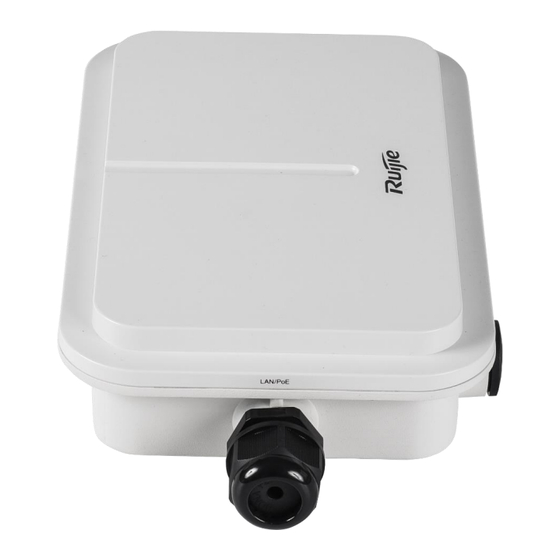
About the RG-AP680-L Access Point The RG-AP680-L is a dual-radio and dual-stream access point designed to cover outdoor areas. Compliant with the IEEE 802.11ax standard, the access point delivers a combined data rate of 2.975 Gbps, with up to 575 Mbps in the 2.4 GHz band and 2.4 Gbps in the 5 GHz band. - Page 9 Hardware Installation and Reference Guide Product Overview Figure 1-2 Top View of Access Point Figure 1-3 Side View of Access Point...
-
Page 10: Package Contents
The nameplate is at the bottom of the access point. Package Contents Table 1-2 Package Contents Item Quantity RG-AP680-L Access Point Mounting Plate Assembly (Including a mounting plate and a mounting arm) Mounting Bracket M5 Screw M8 Screw M6 x 50 mm Expansion Anchor... -
Page 11: Technical Specifications
Dimensions and Weight Table 1-3 Dimensions and Weight Dimensions and RG-AP680-L Weight Access point: 251 mm × 168 mm × 64 mm (9.88 in. x 6.61 in. x 2.52 in.) Physical Dimensions (W Mounting plate assembly: 130 mm × 231 mm × 39 mm (5.12 in. x 9.09 in. x 1.54 ×... -
Page 12: Port Specifications
Hardware Installation and Reference Guide Product Overview Radio Specifications RG-AP680-L Radio2: 802.11a/n/ac/ax, 5.150 GHz to 5.350 GHz Note: The operating radio is country-specific. 2.4 GHz: 575 Mbps Max. Data Rate 5 GHz: 2.4 Gbps Combined: 2.975 Gbps Antenna Type Built-in smart antennas 2.4 GHz: 4 dBi... -
Page 13: Power Supply And Consumption
Three RSSI LEDs Button One Reset button 1.4.4 Power Supply and Consumption Table 1-6 Power Supply and Consumption Power Supply and RG-AP680-L Consumption 1. DC power supply (48 V/0.35 Input Power Supply 2. PoE/PoE+ power supply (IEEE 802.3af/at-compliant) Max. Power 12.95 W... -
Page 14: Led And Button
Hardware Installation and Reference Guide Product Overview Environment and RG-AP680-L Reliability Operating humidity: 0% to 100% RH (non-condensing) Humidity Storage humidity: 0% to 100% RH (non-condensing) IP Rating IP68 Anti-corrosion Rating 48h salt spray test Safety Standard GB 4943.1, IEC 60950-1, IEC 60825-1... -
Page 15: Optical Module
Hardware Installation and Reference Guide Product Overview Table 1-9 Reset Button Button Operation Result Press and hold the button for less Restart the access point. than 2 seconds. Reset button Press and hold the button for more Restore the access point to factory settings. than 5 seconds. - Page 16 Hardware Installation and Reference Guide Product Overview Table 1-12 Rate Negotiation for an Electrical Port on the Peer Device Negotiation Rate Supported by the Port on the Peer Device Optical Port Rate of O/E Conversion 1 Gbps/10 1 Gbps/2.5 Gbps/10 Access Module Rate 1 Gbps...
-
Page 17: Preparing For Installation
Hardware Installation and Reference Guide Preparing for Installation Preparing for Installation Safety Precautions Note ● To avoid personal injury and device damage, carefully read the safety precautions before you install the device. ● The following safety precautions may not cover all possible dangers. 2.1.1 General Safety Precautions ... -
Page 18: Storage Security
Hardware Installation and Reference Guide Preparing for Installation Find the position of the indoor emergency power switch before installation. Cut off the power switch in case of accidents. Check the access point carefully for confirmation before shutting down the power supply. ... -
Page 19: Cleanness Requirements
Hardware Installation and Reference Guide Preparing for Installation access point and severely affecting its service life. Note The ambient temperature and humidity of the device are measured at the point that is 1.5 m (59.06 in.) above the floor and 0.4 m (15.75 in.) before the device when there is no protective plate in front or at the back of the device. -
Page 20: System Grounding Requirements
Take electromagnetic shielding measures when necessary. 2.2.8 Lightning Protection Requirements The RG-AP680-L can guard against lightning strikes. As an electric device, too strong lightning strikes may still damage the device. Take the following lightning protection measures: Ensure that the neutral point of the AC power socket is in good contact with the ground. -
Page 21: Other Requirements
Special tools Anti-static wrist strap, stripping plier, crimping plier, and wire cutter Meters Multimeter and bit error rate tester (BERT) Other tools PC, display, and keyboard Note The RG-AP680-L is delivered without a tool kit. The tool kit is customer-supplied. -
Page 22: Installing The Access Point
Hardware Installation and Reference Guide Installing the Access Point Installing the Access Point The RG-AP680-L access point must be installed at a fixed position. Caution Before installing the device, make sure that you have carefully read the requirements described in Chapter 2. -
Page 23: Before You Begin
Hardware Installation and Reference Guide Installing the Access Point Before You Begin Carefully plan and arrange the installation location, networking mode, power supply, and cabling before installing the device. Confirm the following requirements before installation: The installation location provides sufficient space for heat dissipation. ... -
Page 24: Precautions
Hardware Installation and Reference Guide Installing the Access Point Figure 3-3 Dimensions of Mounting Bracket Precautions To ensure the normal operation and prolonged service life of the access point, observe the following safety precautions: Do not power on the device during installation. ... -
Page 25: Mounting The Access Point On A Pole
Wi-Fi Coverage of Access Point 3.4.2 Mounting the Access Point on a Pole (1) Secure the mounting plate assembly to the bottom of the RG-AP680-L access point using four M5 screws. Figure 3-5 Securing Mounting Plate Assembly to Access Point... - Page 26 Hardware Installation and Reference Guide Installing the Access Point ○ Vertical pole mounting: Secure the mounting bracket to a vertical pole by threading two hose clamps through the square holes of the mounting bracket. Keep the part of the bracket noted by TOP on top. Figure 3-6 Securing Mounting Bracket to Vertical Pole ○...
- Page 27 Hardware Installation and Reference Guide Installing the Access Point (3) Position the mounting arm on the mounting bracket with its two holes aligned to the screw holes on the mounting bracket. Figure 3-8 Positioning Mounting Arm on Mounting Bracket (4) Use two M8 screws to secure the mounting arm to the mounting bracket.
-
Page 28: Mounting The Access Point On A Ceiling
Hardware Installation and Reference Guide Installing the Access Point Figure 3-9 Securing Mounting Arm to Mounting Bracket 3.4.3 Mounting the Access Point on a Ceiling (1) Secure the mounting bracket to a ceiling using four M6 expansion anchors. Figure 3-10 Securing Mounting Bracket to Ceiling (2) Loosen the two M6 screws on the mounting plate assembly to remove the mounting arm. - Page 29 Rotating Mounting Arm by 90 Degrees Clockwise (3) Secure the mounting plate assembly to the bottom of the RG-AP680-L access point using four M5 screws. (4) Position the mounting arm on the mounting bracket with its two holes aligned to the screw holes on the mounting bracket.
- Page 30 Hardware Installation and Reference Guide Installing the Access Point (5) Use two M8 screws to secure the mounting arm to the mounting bracket. Figure 3-13 Securing Mounting Arm to Mounting Bracket...
-
Page 31: Removing The Access Point
Hardware Installation and Reference Guide Installing the Access Point Caution ● Use matching screws for the screw holes, and tighten the structural parts in different installation links. ● Tighten all fastening screws. If any screw is not installed, the device may vibrate violently, shift, or fall down. -
Page 32: Installing The Ethernet Cable
Hardware Installation and Reference Guide Installing the Access Point Figure 3-15 Installing Grounding Cable 3.6.2 Installing the Ethernet Cable Caution ● Make sure that the RJ45 connector is inserted into the access point correctly. Otherwise, the RJ45 connector will be damaged when you tighten the cable gland. ●... -
Page 33: Installing The Fiber-Optic Cable
Hardware Installation and Reference Guide Installing the Access Point Figure 3-17 Wrapping Waterproof Materials Around Ethernet Cable (4) Insert the RJ45 connector into the Ethernet/PoE port of the access point, and tighten the cable gland assembly in sequence of part B, C and D to complete the installation. 3.6.3 Installing the Fiber-Optic Cable Note... -
Page 34: Installing The Power Cord
Hardware Installation and Reference Guide Installing the Access Point (5) Tighten D (compression cap) until C (grommet) and B (gasket) compress on to the cable and provide cable strain relief. Use a waterproof tape to tighten the cable gland. Caution When removing the cable gland, proceed in the reverse order of the installation. -
Page 35: Checklist After Installation
Hardware Installation and Reference Guide Installing the Access Point Caution After the cables are bundled, check whether waterproof measures are taken properly. Checklist After Installation 3.8.1 Checking the Access Point Verify that the external power supply matches with the requirement of the access point. ... -
Page 36: Verifying Operating Status
Hardware Installation and Reference Guide Verifying Operating Status Verifying Operating Status Setting up Configuration Environment The access point can be powered by PoE or local power . When the access point is powered by using DC or PoE, verify that the power supply functions properly and meets safety requirements. -
Page 37: Monitoring And Maintenance
If the access point works in the fat mode, you can log in to the access point for remote maintenance. If the access point works in the fit mode, you can use a wireless controller to manage and maintain the access point uniformly. Hardware Maintenance If the hardware is faulty, please contact Ruijie technical support. -
Page 38: Common Troubleshooting
Check whether the LEDs are normal. Check whether cables are properly connected with ports. Contact Ruijie technical support to check whether hardware faults exist. Common Faults 6.2.1 Ethernet Port Is Not Working After the Ethernet Cable Is Plugged In Verify that the peer device is working properly. -
Page 39: Led Is Steady Green
Hardware Installation and Reference Guide Common Troubleshooting 6.2.4 LED Is Steady Green The device performs initialization after power-on. During this period, the LED keeps steady green and does not turn normal blue until the initialization is completed. Note: If the steady green persists for an hour, the device initialization fails and the device is faulty. -
Page 40: Appendix
Hardware Installation and Reference Guide Appendix Appendix Connectors and Media 1000BASE-T/100BASE-TX/10BASE-T port The 1000BASE-T/100BASE-TX/10BASE-T is a 10/100/1000 Mbps port that supports auto-negotiation and auto MDI/MDIX Crossover. Compliant with IEEE 802.3ab, the 1000BASE-T port requires 100-ohm Category 5/5e UTP or STP with a maximum distance of 100 meters (328.08 feet). - Page 41 Hardware Installation and Reference Guide Appendix Socket Plug Output Transmit Data+ Input Receive Data+ Output Transmit Data- Input Receive Data- 4, 5, 7, 8 Not Used Not Used The following figure shows feasible connections of the straight-through and crossover twisted pairs for a 100BASE-TX/10BASE-T port.
-
Page 42: Cabling
Hardware Installation and Reference Guide Appendix Cabling During installation, route cable bundles upward or downward along the sides of the rack depending on the actual situation in the equipment room. All cable connectors should be placed at the bottom of the cabinet rather than be exposed outside of the cabinet. - Page 43 Hardware Installation and Reference Guide Appendix ○ The cable management brackets and cabling troughs inside and outside the cabinet should be smooth without sharp corners. ○ The metal hole traversed by cables should have a smooth and fully rounding surface or an insulated lining.
- Page 44 Hardware Installation and Reference Guide Appendix ○ The power cables connecting moving parts such as door grounding wires should be reserved with some access after being assembled to avoid suffering tension or stress. When a moving part reaches the installation position, the remaining cable part should not touch heat sources, sharp corners, or sharp edges.
-
Page 45: Optical Modules And Specifications
Hardware Installation and Reference Guide Appendix Optical Modules and Specifications We provide appropriate optical modules according to the port types. You can select the module to suit your specific needs. The optical module types and corresponding specifications are provided for reference. Table 7-1 SFP Modules and Specifications Intensity of... -
Page 46: Dc Connector Specifications
Hardware Installation and Reference Guide Appendix DC Connector Specifications Input voltage: 48 V DC; rated current: 0.35 A Table 7-4 DC Connector Specifications Inner Diameter Outer Diameter Depth Polarity 2.0 mm (0.08 in.) 6.3 mm (0.25 in.) 9.8 mm (0.39 in.) Inner Positive, Outer Negative Figure 7-8...
Need help?
Do you have a question about the RG-AP680-L and is the answer not in the manual?
Questions and answers