Table of Contents
Advertisement
Quick Links
Advertisement
Table of Contents

Related Manuals for Ruijie RG-AP630 Series


Summary of Contents for Ruijie RG-AP630 Series
- Page 1 RG-AP630 Series Access Point Hardware Installation and Reference Guide V1.8...
- Page 2 This document is provided “as is”. The contents of this document are subject to change without any notice. Please obtain the latest information through the Ruijie Networks website. Ruijie Networks endeavors to ensure content accuracy and will not shoulder any responsibility for losses and damages caused due to content omissions, inaccuracies or errors.
- Page 3 It is intended for the users who have some experience in installing and maintaining network hardware. At the same time, it is assumed that the users are already familiar with the related terms and concepts. Obtaining Technical Assistance Ruijie Networks Website: https://www.ruijienetworks.com/ Technical Support Website: https://ruijienetworks.com/support...
-
Page 4: Product Overview
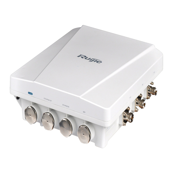
· 1 Product Overview The RG-AP630 is a wireless access point (AP) designed by Ruijie for next-generation high-speed wireless LANs. Adhering to the latest 802.11ac standard, the AP delivers an access rate of up to 1.75Gbps. It features security, radio frequency (RF) control, mobile access, Quality of Service (QoS), and seamless roaming. -
Page 5: Product Appearance
· Storage: -40° C to 85° C (-40° F to 185° F) Operating: 0% to 100% (non-condensing) Humidity Storage: 0% to 100% (non-condensing) IP Rating IP68 Weight <2.5 kg (5.51 lbs) Safety Standards GB4943, EN60601-1-2 (medical care), UL/CSA 60950-1, EN/IEC 60950-1, EN/IEC 60950-22 GB9254-2008, EN301 489, EN55022, FCC Part15, RSS-210 EMC Standards Table 1-2 LEDs of RG-AP630... -
Page 6: Front View
· 1.3 Front View Figure 1-2 RG-AP630 Front View 1. 2.4GHz antenna connector 2. Console port 3.10/100/1000 Base-T auto-sensing Ethernet/PoE 4.10/100/1000 Base-T auto-sensing Note: OUT port Ethernet/PoE IN port 5. SFP combo port 6. 5GHz antenna connector 1.4 Power Supply The AP supports 802.3af/at compatible PoE. -
Page 7: Preparing For Installation
· 2 Preparing for Installation To prevent device damage and physical injury, please read carefully the safety recommendations described in this chapter. Recommendations do not cover all possible hazardous situations. 2.1 Grounding and Lightning Protection Keep the grounding connection within 30 m, and use a 40 mm x 4 mm or 50 mm x 5 mm ground bar of hot-dip zinc-coated flat steel sheet. -
Page 8: Temperature And Humidity
· 2.2.1 Temperature and Humidity Table 2-1 Required Temperature and Humidity for the RG-AP630 Series Operating Temperature -40° C to 65° C (-40° F to 149° F) Operating Humidity 0% to 100% (non-condensing) 2.2.2 Outdoor Installation The AP can be installed outdoors and mounted on a wall or pole. -
Page 9: Fiber Connection
· Radiation interference occurs when energy (usually radio frequency energy) is emitted from a device and propagated through space to disrupt other devices. The interference source can be part of disrupted system or a fully electrically isolated unit. Conduction interference occurs when interference is transferred from one unit to another through cables, which are usually electromagnetic wires or signal cables connected between the source and the device(s) experiencing interference. -
Page 10: Installing The Access Point
· 3 Installing the Access Point Before installing the AP, make sure you have carefully read the requirements described in Chapter 2. 3.1 Installation Flowchart Start Check Choose the Site Install the Bracket on a Wall Install the Bracket on a Pole Install the AP Install External Antenna (Optional) Adjust Antenna Orientation... -
Page 11: Before You Begin
· 3.2 Before You Begin Before you install the AP, verify that all the parts in the packing list are there and make sure that: The installation site meets temperature and humidity requirements. The installation site is equipped with a proper power supply. ... - Page 12 · Attach the tie rod to the mounting plate and fasten the rod with the supplied M8 x 40 screws. See Figure 3-2 Figure 3-2 Fixing the Tie Rod on the Mounting Plate Wall mount...
- Page 13 · 3) Use the supplied cross-shaped bracket and M8 x 60 screws to implement the wall mount. Attach the cross-shaped bracket to the wall and mark the screw hole locations. See figure 3-3. Figure 3-3 Installing the M8 bolts b. Hang the AP with the AP-side mounting bracket module to the cross-shaped bracket and tighten the M8×40 screws to secure the AP.
- Page 14 · b. Hang the AP with the AP-side mounting bracket module to the cross-shaped bracket and tighten the M8×40 screws to secure the AP. See figure 3-6. Figure 3-6 Installing the AP on a Vertical Pole Horizontal pole mount Figure 3-7 Fixing the Bracket on a Horizontal Pole...
-
Page 15: Adjusting Antenna Orientation
· Figure 3-8 Installing the AP on the Horizontal Pole The procedure of horizontal pole mount is similar as that of a vertical mount. 3.5 Adjusting Antenna Orientation Both directional and omni-directional antennas are available for the RG-AP630. The integrated antenna is in parallel with the upper shell. - Page 16 · Figure 3-10 Clockwise Horizontal Rotation (+60° ) (-60° to +60° horizontal rotation available) Figure 3-11 Vertical Rotation (0° )
- Page 17 · Figure 3-12 Clockwise Vertical Rotation (+60° ) (0° to 90° vertical rotation available) RG-AP630(IODA) Antenna Orientation Figure 3-13 Anticlockwise Vertical Rotation (-90° )
-
Page 18: Connecting Cables
· 3.6 Installing a Security Lock (Optional) The security lock is customer-supplied. The lock loop on the AP is for your security needs. You can fasten the AP to a fixture as follows: Fasten the cable of a security lock to a fixture; Secure the lock plate into the lock loop. - Page 19 · Connecting the network cable Waterproofing material is customer-supplied. Trim the network cable according to the distance between the AP and the power supply. Thread the cable through liquid-tight adapter and add a plug to the end. See figure 3-16. Figure 3-16 Threading the Network Cable Wrap the cable between B and C upwards with two or three layers of liquid-tight material.
-
Page 20: Installing Outdoor Antennas (Optional)
· Figure 3-18 Threading the Fiber Insert the plug of the fiber into the SPF port. Tighten A. Combine B and C and put the combination into A. Tighten D before applying waterproof glue to its joint with A. Before removing the optical fiber, dismantle the liquid-tight adapter first and then the plug. If the diameter of LC-LC fiber is not 2.7±0.2mm, waterproofness of the adapter cannot be guaranteed. - Page 21 · Installing Outdoor Omnidirectional Antennas Omnidirectional antennas must be kept at least one meter away from any metal. Do not weld the lightning rod onto the pole installed with an omni-directional antenna. Place the lightning rod in the middle of two omni-directional antennas.
-
Page 22: Appendix A Connectors And Media
· Appendix A Connectors and Media 1000BASE-T/100BASE-TX/10BASE-T The 1000BASE-T/100BASE-TX/10BASE-T is a 10/100/1000 Mbps auto-negotiation port that supports auto MDI/MDIX. Compliant with IEEE 802.3ab, 1000BASE-T requires Category 5e 100-ohm UTP or STP (STP is recommended) with a maximum distance of 100 meters (328 feet). 1000BASE-T requires all four pairs of wires be connected for data transmission, as shown in Figure A-1. - Page 23 · You can choose to use single mode or multimode fibers according to the transceiver module types. Figure A-3 shows connection of fiber cables. Figure A-3 Fiber Connection...
-
Page 24: Appendix B Mini-Gbic Module Specifications
· Appendix B Mini-GBIC Module Specifications Ruijie provides various Gigabit SFP transceivers (Mini-GBIC modules) for interfaces of wireless access controllers. You can select the most suitable SFP modules as needed. This appendix describes the models and specifications of some of the Gigabit SFP transceivers for your reference.
Need help?
Do you have a question about the RG-AP630 Series and is the answer not in the manual?
Questions and answers